US495342A - jacobs - Google Patents
jacobs Download PDFInfo
- Publication number
- US495342A US495342A US495342DA US495342A US 495342 A US495342 A US 495342A US 495342D A US495342D A US 495342DA US 495342 A US495342 A US 495342A
- Authority
- US
- United States
- Prior art keywords
- chamber
- diaphragm
- pipe
- digesting
- liquid
- Prior art date
- Legal status (The legal status is an assumption and is not a legal conclusion. Google has not performed a legal analysis and makes no representation as to the accuracy of the status listed.)
- Expired - Lifetime
Links
- 239000007788 liquid Substances 0.000 description 24
- 239000007921 spray Substances 0.000 description 7
- 238000009408 flooring Methods 0.000 description 6
- 239000000463 material Substances 0.000 description 6
- 238000007664 blowing Methods 0.000 description 4
- 229910000746 Structural steel Inorganic materials 0.000 description 3
- 238000010276 construction Methods 0.000 description 3
- 238000010411 cooking Methods 0.000 description 3
- 238000007599 discharging Methods 0.000 description 3
- 239000010902 straw Substances 0.000 description 3
- 230000008878 coupling Effects 0.000 description 2
- 238000010168 coupling process Methods 0.000 description 2
- 238000005859 coupling reaction Methods 0.000 description 2
- 238000006880 cross-coupling reaction Methods 0.000 description 2
- 239000012530 fluid Substances 0.000 description 2
- 230000008439 repair process Effects 0.000 description 2
- XLYOFNOQVPJJNP-UHFFFAOYSA-N water Substances O XLYOFNOQVPJJNP-UHFFFAOYSA-N 0.000 description 2
- 210000004262 dental pulp cavity Anatomy 0.000 description 1
- 230000029087 digestion Effects 0.000 description 1
- 239000013505 freshwater Substances 0.000 description 1
- 235000000396 iron Nutrition 0.000 description 1
- 239000002184 metal Substances 0.000 description 1
- 229910052751 metal Inorganic materials 0.000 description 1
- 238000004537 pulping Methods 0.000 description 1
- 235000013311 vegetables Nutrition 0.000 description 1
- 239000002023 wood Substances 0.000 description 1
Images

Classifications
-
- D—TEXTILES; PAPER
- D21—PAPER-MAKING; PRODUCTION OF CELLULOSE
- D21C—PRODUCTION OF CELLULOSE BY REMOVING NON-CELLULOSE SUBSTANCES FROM CELLULOSE-CONTAINING MATERIALS; REGENERATION OF PULPING LIQUORS; APPARATUS THEREFOR
- D21C7/00—Digesters
- D21C7/14—Means for circulating the lye
Definitions
- My invention relates to the means or apparatus for making stock for paper or pulp board from wood, straw or other-fibrous vegetable matter and more particularly to that part of the apparatus known as the digester and it consists in the means for applying steam to the digesting chamber for cooking or pulping the material and also for blowing out or discharging the digested material or pulp from said chamber, ashereinafter described, and claimed.
- A indicates the shell of the digester, made, preferably, in the form of a strong, upright cylinder, of any desired capacity and provided in its upper end or head with a manhole at B, through which the cylinder is charged, and, preferably, also, with one B in I lower end or head of the shell.
- the shell Near its lower end or head the shell is provided with a perforated diaphragm C, which serves to form a liquid chamber A in the lower end of the shell, separated from the pulp chamber A, proper, by said diaphragm through which the digesting liquid is strained and separated from the pulp material in the chamber A.
- This diaphragm O is perforated throughout its entire extent and is formed or made up of strips or sections sufiiciently narrow to pass through the manhole B, or B and laid in the form of a flooring and supported upon shouldered tubes D, which at their lower ends rest on the The sections thus laid and forming a diaphragm fitting Serial No. 432,654, (No model.) 1
- angle-iron bars 0, c which are clamped down on the flooring strips or plates by bolts 01, which pass through the horizontal flange of the angle iron and through the tubes D and lower end of the shell.
- the angle irons c are curved to conform to the side walls of the shell and extend entirely around inside the latter-covering the junction of the flooring sections therewith, and, may be riveted or otherwise secured to the flooring or shell or both as may be found expedient.
- the upright flanges of the angle iron bars serve to materially stifien the flooring and permit the use of lighter metal therefor than would otherwise be practicable.
- the flooring is provided, at O','with a manhole through which access may be had to the liquid chambar for construction, repairs, &c.
- the shell thus constructed is supported on suitable mason work by strong, angular brackets E, E,,the upright arms of which are securely riveted or bolted to the side walls of the shell.
- the F and F represent branches of a steam pipe connecting with any conveniently arranged steam generator, the pipe F having branches provided with upturned ends or nozzles f, f, which penetrate or project up through the diaphragm and discharge into the digesting chamber, and the pipe F extends around the shell and hasbranches or nozzles f f which pass through the side walls of the shell immediately above the diaphragm, so that all steam admitted to the digesting chamber will enter at the lower end thereof, immediately above the perforated diaphragm.
- G indicates thedischarge pipe, connecting with the digesting chamber A through the I side wall thereof, immediately above the pering out the contents of the digestingchamber.
- the circulating pipe H connects with the bottom of the liquid chamber A and extends thence to one side of and up to the top of the shell and through the latter where it has a spray pipe orpipes I, connected with it.
- the spray pipe made up into rectangular form, from straight pipe sections united by corner or angle couplings, but any suitable form may be given to it.
- the sections of this pipe are perforated on their lower sides, the perforations being formed at different angles or inclinations so as to spray the entire surface of the contents of the digesting chamber.
- the circulating pipe H is provided intermediate its ends with a cross section or coupling J, in which is mounted a four-way valve of any suitable construction.
- the lateral branches H and H from this cross-coupling connect the upright circulating pipe with a pump at M, actuated in any suitable manner and which gives a forced circulation of the digesting fluid through the pipe II fromthe liquid chamber A to the spray pipe I in a manner well understood.
- Other pipes L, L, connect the pump M-and pipe H with suitable liquid tanks for supplying fresh water or digesting liquid to the digester, as may be required.
- the spray pipe is regarded as important in this fluid circulation, described, as it distributes the liquid evenly over the surface of the contents of the digesting chamber.
- the liquid has been brought by a single pipe and in a stream either directly into said chamber or above a perforated diaphragm through which the water passed at the nearest point possible,but which, through its liabilityto become obstructed, failed to distribute the liquid evenly over the surface of 'the mass of material in such manner as to secure the best results.
- Heat may be applied to the digester, either through a furnace located under it or in any usual manner and the liquids employed may .be such as are usuallyemployed for the purpose, whether alkaline or other solutions, for
- the digester having a perfoing a liquid chamber from the digesting chamrated diaphragm near its lower end, separat- 13o her, in combination with a series of steam pipes entering said digesting chamber through said diaphragm and a series of pipes also entering said chamber through the side walls,
Landscapes
- Paper (AREA)
Description
(No Model.)
2 Sheets-Sheet 1.
'0. s. JACOBS.
DIGESTER.
Patented Apr. 11, 1893.
15m EIT'III' fiver 6: W055, 25 1/ um (No Model.) 2 Sheets-Sheet 2.
0. S JACOBS. DIGESTER.
No. 495,342. Patented A r, 11; 1893.
$ 5 Q Innafifur: v JZ'OZS,
was
DHGESTER.
SPECIFICATION forming part of Letters Patent No. 495,342, dated April 11, 1893.
Application filed May 11, 1892- To all whom it may concern:
Be it known that I, QLIVER S. JACOBS, a citizen of the United States, and a resident of St. Marys, county of Auglaize, and State of Ohio, have invented a new and useful Improvement in Digesters, of which the following is a full, clear, and exact description, reference being had to the accompanying drawings, making part of this specification.
My invention relates to the means or apparatus for making stock for paper or pulp board from wood, straw or other-fibrous vegetable matter and more particularly to that part of the apparatus known as the digester and it consists in the means for applying steam to the digesting chamber for cooking or pulping the material and also for blowing out or discharging the digested material or pulp from said chamber, ashereinafter described, and claimed.
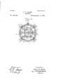
In the accompanying drawingsz-Figure 1 represents a vertical section through a digester, embracing my improvements, showing the circulating pipes, 850., in side elevation. Fig. 2 represents a horizontal section through the digester shell, on the line zra:, Fig. 1, but showing the spray pipe in plan view.
A indicates the shell of the digester, made, preferably, in the form of a strong, upright cylinder, of any desired capacity and provided in its upper end or head with a manhole at B, through which the cylinder is charged, and, preferably, also, with one B in I lower end or head of the shell.
one side for facilitating access to the interior of the shell in the construction or for repairs or other purpose. Near its lower end or head the shell is provided with a perforated diaphragm C, which serves to form a liquid chamber A in the lower end of the shell, separated from the pulp chamber A, proper, by said diaphragm through which the digesting liquid is strained and separated from the pulp material in the chamber A. This diaphragm O is perforated throughout its entire extent and is formed or made up of strips or sections sufiiciently narrow to pass through the manhole B, or B and laid in the form of a flooring and supported upon shouldered tubes D, which at their lower ends rest on the The sections thus laid and forming a diaphragm fitting Serial No. 432,654, (No model.) 1
I snugly the cylindrical shell, have their joints covered by angle-iron bars 0, c, which are clamped down on the flooring strips or plates by bolts 01, which pass through the horizontal flange of the angle iron and through the tubes D and lower end of the shell. The angle irons c are curved to conform to the side walls of the shell and extend entirely around inside the latter-covering the junction of the flooring sections therewith, and, may be riveted or otherwise secured to the flooring or shell or both as may be found expedient. The
upright flanges of the angle iron bars serve to materially stifien the flooring and permit the use of lighter metal therefor than would otherwise be practicable. The flooring is provided, at O','with a manhole through which access may be had to the liquid chambar for construction, repairs, &c. The shell thus constructed is supported on suitable mason work by strong, angular brackets E, E,,the upright arms of which are securely riveted or bolted to the side walls of the shell.
F and F represent branches of a steam pipe connecting with any conveniently arranged steam generator, the pipe F having branches provided with upturned ends or nozzles f, f, which penetrate or project up through the diaphragm and discharge into the digesting chamber, and the pipe F extends around the shell and hasbranches or nozzles f f which pass through the side walls of the shell immediately above the diaphragm, so that all steam admitted to the digesting chamber will enter at the lower end thereof, immediately above the perforated diaphragm. Further, by the arrangement of the several steampipes, whereby they are made to enter the digesting chamber at its extreme lower end, .beneath the contents of said chamber, but above the the diaphragm separating it from the liquid chamber, as described, live or superheated steam can be introduced,in numerous jets, beneath the entire .contents of the digesting chamber whenever this is found necessary, as it frequently is, for the proper cooking or digestion of the pulp material. Steam has heretofore been admitted near the bottom of the digesting chamber, in a single jet, for blowing out the contents, but never, so far as I am aware, in numerous jets distributed to cover the bottom of said contents for causing the steam to penetrate the entire mass for cooking it.
G indicates thedischarge pipe, connecting with the digesting chamber A through the I side wall thereof, immediately above the pering out the contents of the digestingchamber.
In this last named arrangement of the steam jets and discharge outletthe steam entered the liquid in the liquid chamber, and meeting the resistance and condensing action of the liquid therein and the further resistance due to the perforations in the diaphragm being clogged and obstructed by the pulp drawn forcibly down thereon by the action of the circulation, the result was that the action of the steam tended to blow the liquid out of the liquid chamber, into the circulating pipes and so around and into the top of the digesting chamher, until the pressure above and below was equalized and the blowing out, if effected at all, was very imperfect:-whereas, in my arrangement, the steam being admitted immediately over the diaphragm, it can communi cate with the circulating pipes only through the diaphragm, obstructed as described, or through the contents of the digesting chamber itself, and then in a reverse direction, and the result, with the discharge pipe connecting with the side of said chamber above the diaphragm, as described, is an efiectual and thorough blowing out of the contents of said chamber or so much thereof as may be desired,'controlled by suitable steam cocks and discharge outlet valve.
The circulating pipe H connects with the bottom of the liquid chamber A and extends thence to one side of and up to the top of the shell and through the latter where it has a spray pipe orpipes I, connected with it. We have shown the spray pipe made up into rectangular form, from straight pipe sections united by corner or angle couplings, but any suitable form may be given to it. The sections of this pipe are perforated on their lower sides, the perforations being formed at different angles or inclinations so as to spray the entire surface of the contents of the digesting chamber.
The circulating pipe H is provided intermediate its ends with a cross section or coupling J, in which is mounted a four-way valve of any suitable construction. The lateral branches H and H from this cross-coupling connect the upright circulating pipe with a pump at M, actuated in any suitable manner and which gives a forced circulation of the digesting fluid through the pipe II fromthe liquid chamber A to the spray pipe I in a manner well understood. The course of the liquid, in the ordinary operation as described,
lower part of circulating pipe to'the four way valve in the cross coupling J, thence through the lateral pipe ll to the pump at M thence backthrough the lateral 1-1 to the valve at J and thence up through the upper portion of the pipe II to the spray pipe. When, for any purpose, it is desired to reverse the direction of the liquid throughthe circulating pipe, as, for "example, when the diaphragm becomes choked the four way valve is suitably turned and the pump draws the liquid down through will be from the liquid chamber through the the valve and lateral I1 and forces it back through the lateral H to the valve and thence through the lower portion of the pipe H into the liquid chamber and up through the perforated diaphragm, thereby removing the obstructing matter. Other pipes L, L, connect the pump M-and pipe H with suitable liquid tanks for supplying fresh water or digesting liquid to the digester, as may be required. The spray pipe is regarded as important in this fluid circulation, described, as it distributes the liquid evenly over the surface of the contents of the digesting chamber. Heretofore the liquid has been brought by a single pipe and in a stream either directly into said chamber or above a perforated diaphragm through which the water passed at the nearest point possible,but which, through its liabilityto become obstructed, failed to distribute the liquid evenly over the surface of 'the mass of material in such manner as to secure the best results.
Heat may be applied to the digester, either through a furnace located under it or in any usual manner and the liquids employed may .be such as are usuallyemployed for the purpose, whether alkaline or other solutions, for
digesting the materials, or pure water for cleansing the pulp, &c.
' Having now described my invention, what I' claim as new, and desire to secure by Letters Patent, isa 1, In a machine for making stock for paper, straw board, 850.. the digester provided with aperforated diaphragm near its lower.
end, separating a liquid chamber from the digesting chamber. in combination with the series of steam pipes entering the digesting chamber and discharging immediately above the diaphragm and beneath the contents of said digesting chamber, substantially as described.
2. In a machine for making stock for straw or pulp board, the digester having a perfoing a liquid chamber from the digesting chamrated diaphragm near its lower end, separat- 13o her, in combination with a series of steam pipes entering said digesting chamber through said diaphragm and a series of pipes also entering said chamber through the side walls,
immediately above said diaphragm and all discharging at the bottom of said digesting chamber, substantially as and for the purpose described.
In testimony whereof I have hereiihto set my hand this 29th day of April, A. D. 1892 OLIVER S. JACOBS. Witnesses:
REXFORD M. SMITH, R. II. TAYLOR.
Publications (1)
| Publication Number | Publication Date |
|---|---|
| US495342A true US495342A (en) | 1893-04-11 |
Family
ID=2564181
Family Applications (1)
| Application Number | Title | Priority Date | Filing Date |
|---|---|---|---|
| US495342D Expired - Lifetime US495342A (en) | jacobs |
Country Status (1)
| Country | Link |
|---|---|
| US (1) | US495342A (en) |
-
0
- US US495342D patent/US495342A/en not_active Expired - Lifetime
Similar Documents
| Publication | Publication Date | Title |
|---|---|---|
| US1852179A (en) | Steam washing machine | |
| US642460A (en) | Apparatus for producing wort, hop-beer, washing filter-pulp, &c. | |
| US2534324A (en) | Process for separating cooking liquor from pulp | |
| US530635A (en) | blackman | |
| US34648A (en) | Improved condenser for stills | |
| US735878A (en) | Wheat steamer and heater. | |
| US401610A (en) | Apparatus for treating vegetable substances | |
| US399200A (en) | Apparatus for the pasteurization of beer | |
| US881434A (en) | Apparatus for boiling lime and sulfur. | |
| US2845347A (en) | Apparatus and method for digesting | |
| US1061767A (en) | Wood-pulp digester. | |
| US374346A (en) | Haeey a | |
| US57218A (en) | Improved apparatus for extracting tanning matters from bark | |
| US4684442A (en) | Oxygen reactor deaeration tank and system | |
| US464199A (en) | maccoemack | |
| US410744A (en) | Apparatus for dyeing | |
| US639844A (en) | Washboiler. | |
| US35357A (en) | Improvement in apparatus for bleaching and cleansing textile fabrics | |
| US114457A (en) | Improvement in wash-boilers | |
| US361015A (en) | Digester for wood pulp | |
| US333105A (en) | And michael zieb | |
| US55835A (en) | Improved apparatus for making paper-pulp from wood, straw, and other materials | |
| US1658216A (en) | Pulp digester | |
| US654866A (en) | Dust-arrester. | |
| US1784197A (en) | natwick |