US4940407A - Gas-fired fireplace log set - Google Patents
Gas-fired fireplace log set Download PDFInfo
- Publication number
- US4940407A US4940407A US07/346,779 US34677989A US4940407A US 4940407 A US4940407 A US 4940407A US 34677989 A US34677989 A US 34677989A US 4940407 A US4940407 A US 4940407A
- Authority
- US
- United States
- Prior art keywords
- gas
- flame
- assembly
- logs
- plenum
- Prior art date
- Legal status (The legal status is an assumption and is not a legal conclusion. Google has not performed a legal analysis and makes no representation as to the accuracy of the status listed.)
- Expired - Fee Related
Links
- 238000003491 array Methods 0.000 claims description 5
- 239000011490 mineral wool Substances 0.000 abstract description 15
- 239000002023 wood Substances 0.000 abstract description 12
- 238000002485 combustion reaction Methods 0.000 abstract description 5
- 150000003839 salts Chemical class 0.000 abstract description 4
- 230000000694 effects Effects 0.000 abstract description 3
- 239000007789 gas Substances 0.000 description 27
- 125000006850 spacer group Chemical group 0.000 description 9
- 229910052751 metal Inorganic materials 0.000 description 6
- 239000002184 metal Substances 0.000 description 6
- 239000000463 material Substances 0.000 description 4
- 238000010276 construction Methods 0.000 description 3
- 239000002019 doping agent Substances 0.000 description 3
- ATUOYWHBWRKTHZ-UHFFFAOYSA-N Propane Chemical compound CCC ATUOYWHBWRKTHZ-UHFFFAOYSA-N 0.000 description 2
- UIIMBOGNXHQVGW-UHFFFAOYSA-M Sodium bicarbonate Chemical compound [Na+].OC([O-])=O UIIMBOGNXHQVGW-UHFFFAOYSA-M 0.000 description 2
- FAPWRFPIFSIZLT-UHFFFAOYSA-M Sodium chloride Chemical compound [Na+].[Cl-] FAPWRFPIFSIZLT-UHFFFAOYSA-M 0.000 description 2
- 239000000446 fuel Substances 0.000 description 2
- 239000011521 glass Substances 0.000 description 2
- VNWKTOKETHGBQD-UHFFFAOYSA-N methane Chemical compound C VNWKTOKETHGBQD-UHFFFAOYSA-N 0.000 description 2
- 230000005855 radiation Effects 0.000 description 2
- 229910001220 stainless steel Inorganic materials 0.000 description 2
- 239000010935 stainless steel Substances 0.000 description 2
- 239000004115 Sodium Silicate Substances 0.000 description 1
- 229910000746 Structural steel Inorganic materials 0.000 description 1
- 239000004568 cement Substances 0.000 description 1
- 239000000567 combustion gas Substances 0.000 description 1
- 238000009432 framing Methods 0.000 description 1
- 239000002737 fuel gas Substances 0.000 description 1
- 238000013023 gasketing Methods 0.000 description 1
- 238000010438 heat treatment Methods 0.000 description 1
- 238000009434 installation Methods 0.000 description 1
- 150000002500 ions Chemical class 0.000 description 1
- 239000000203 mixture Substances 0.000 description 1
- 239000003345 natural gas Substances 0.000 description 1
- 230000000149 penetrating effect Effects 0.000 description 1
- 239000001294 propane Substances 0.000 description 1
- 230000000717 retained effect Effects 0.000 description 1
- 238000007665 sagging Methods 0.000 description 1
- 238000004088 simulation Methods 0.000 description 1
- 239000005361 soda-lime glass Substances 0.000 description 1
- 235000017557 sodium bicarbonate Nutrition 0.000 description 1
- 229910000030 sodium bicarbonate Inorganic materials 0.000 description 1
- 239000011780 sodium chloride Substances 0.000 description 1
- 229910001415 sodium ion Inorganic materials 0.000 description 1
- NTHWMYGWWRZVTN-UHFFFAOYSA-N sodium silicate Chemical compound [Na+].[Na+].[O-][Si]([O-])=O NTHWMYGWWRZVTN-UHFFFAOYSA-N 0.000 description 1
- 229910052911 sodium silicate Inorganic materials 0.000 description 1
- 239000003351 stiffener Substances 0.000 description 1
- 231100000331 toxic Toxicity 0.000 description 1
- 230000002588 toxic effect Effects 0.000 description 1
- 238000003466 welding Methods 0.000 description 1
Images
Classifications
-
- F—MECHANICAL ENGINEERING; LIGHTING; HEATING; WEAPONS; BLASTING
- F24—HEATING; RANGES; VENTILATING
- F24C—DOMESTIC STOVES OR RANGES ; DETAILS OF DOMESTIC STOVES OR RANGES, OF GENERAL APPLICATION
- F24C3/00—Stoves or ranges for gaseous fuels
- F24C3/002—Stoves
- F24C3/006—Stoves simulating flames
Definitions
- Gas logs for fireplaces are well known, and typically comprise one or more artificial logs made of a cast noncombustible material which simulates a natural wood log in appearance, and a gas burner positioned beneath the logs and equipped with conventional jets, gas lines and controls. Gas logs are advantageous in providing immediate high-level room heating with convenient and simple ignition, and without the bother of storage and handling of wood logs. Gas logs are usually supplied with either natural gas or propane, and these fuels are readily available and inexpensive.
- a gas log would closely simulate the pleasing aesthetic appearance of a wood-burning fireplace.
- Conventional gas logs fail to achieve this objective, both from the standpoint of flame color, and because of the shape and distribution of the gas flame.
- a gas flame When properly adjusted for safe and complete combustion, a gas flame is blue in color, and lacks the desired yellow-orange flame coloration of burning natural wood. Adjustment of gas-air mixture to produce a yellowish flame can result in unsafe and potentially toxic incomplete combustion which is contrary to standards of the American National Standards Institute and a violation of clean-burning statutory requirements of a growing number of states.
- This invention is directed to an improved gas-fired log set which provides safe and complete gas combustion, and is very close in flame color and appearance to a natural wood fire.
- the log set of this invention has a base which supports a heat-insulating refractory plate, and on which are mounted a gas valve, pilot assembly, and gas lines.
- a burner assembly rests on the refractory plate, and supports a pair of connected and integrally cast-concrete simulated logs and a pair of non-connected logs.
- the burner assembly also supports bodies of rock wool or similar material beneath and between the logs to simulate the glowing embers and under-fire effect of a fireplace burning natural wood.
- the burner assembly has a gas plenum which defines a spaced arrays of gas jets to create flames around and between the logs, and to impinge on the rock-wool bodies and associated support troughs.
- the heated rock wool radiates a glowing-ember appearance which enhances the simulation of a natural wood fire, and the logs and/or the rock wool or similar material are doped with metallic salts to alter the blue color of a complete-combustion gas flame to the pleasing yellow-orange color of a wood fire.
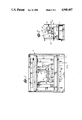
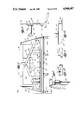
- FIG. 1 is a front elevation of a factory-built fireplace assembly using a gas-log assembly according to the invention
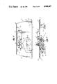
- FIG. 2 is a side view, partly in section, and on line 2--2 of FIG. 1;
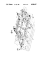
- FIG. 3 is a pictorial view of a burner assembly
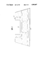
- FIG. 4 is a top plan view of a base for the burner assembly
- FIG. 5 is a front elevation of the base shown in FIG. 4;
- FIG. 6 is a top plan view of a heat-insulating spacer plate
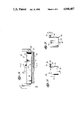
- FIG. 7 is a top plan view of the burner assembly shown in FIG. 3;
- FIG. 8 is an end view on line 8--8 of FIG. 7;
- FIG. 9 is a sectional view on line 9--9 of FIG. 7;
- FIG. 10 is a view on line 10--10 of FIG. 7;
- FIG. 11 is a view on line 11--11 of FIG. 7;
- FIG. 12 is a sectional view on line 12--12 of FlG. 7;
- FIG. 13 is a top plan view of a log-supporting flame spreader for the burner assembly
- FIG. 14 is an end view on line 14--14 of FIG. 13;
- FIG. 15 is a sectional view on line 15--15 of FIG. 13.
- FIGS. 1 and 2 show a factory-built fireplace assembly 10 of sheet-metal construction, and of the heat-circulating zero-clearance type for installation at the framing stage of home or apartment construction.
- Assembly 10 is of a conventional style with a base 11 housing an optional air-circulating fan (not shown), a sliding fire screen 12, and the usual vents and fittings common to factory-built fireplaces.
- a gas-fired log assembly 13 is supported on base 11, and is centrally positioned within a firebox space 14 of the fireplace.
- Log assembly 13 includes a base 17 shown in greater detail in FIGS. 4 and 5, and having a sheet-metal top plate 18 which in plan view is shaped as an isosceles trapezoid.
- the top plate has upwardly turned front and rear edges or lips 19 and 20, and downwardly turned side edges or lips 21.
- Four downwardly extending angle-iron legs 22 are welded to the undersurface of top plate 18 adjacent its four corners.
- An elongated burner support 24 is positioned adjacent the rear edge of top plate 18, and has a base flange 25 welded to the top plate, an upwardly extending leg 26, and a horizontal top flange 27 extending from the leg.
- An elongated and generally rectangular opening 28 is cut through the top plate just forward of support 24.
- a conventional gas valve 30 (the type made by Robertshaw Grayson is satisfactory) is supported on a bracket 31 welded to the underside of the top plate, and the valve has an inlet fitting 32 for connection to a gas supply line (not shown).
- the valve has an outlet line 33 with a conventional air-inlet venturi 34 leading to an upwardly turned flanged connection 35 which is centrally positioned within rectangular opening 28.
- a pilot-light assembly 37 is secured to the upper surface of the top plate adjacent one side of opening 28, and is connected to valve 30 by a small gas tube 38.
- a piezoelectric igniter 39 is positioned adjacent the pilot-light assembly, and is operated by a push button 40 mounted on one of front support legs 22 for access from the front of the fireplace assembly.
- the gas valving, controls and pilot are conventional, and, for brevity, will not be described in greater detail.
- a textured, decorative and heat-insulating spacer plate 43 (FIGS. 2 and 6) made of cast refractory cement is shaped in plan view to correspond to the shape of top plate 18, and rests on the top plate between upwardly turned edges 19 and 20.
- the spacer plate has a raised front edge 44, and a rectangular opening 45 therethrough which extends forwardly from the spacer-plate rear edge. Opening 45 is generally aligned with opening 28 in top plate 18 to provide an open window from the undersurface of the top plate to the upper surface of the spacer plate.
- Assembly 13 further includes a burner assembly 48 (FIGS. 3 and 7-12) with a sheet-metal base panel 49 having upwardly turned side edges 50 and front and rear edges 51 and 52.
- the base panel is again generally shaped in plan view as an isosceles trapezoid, but is somewhat smaller than base 17 and arranged to be generally centrally positioned on spacer plate 43.
- a pair of spaced-apart openings 53 extend through the rearward part of the base panel to provide clearance for pilot-light assembly 37, and to enable circulation of air through the heated zone of the fireplace.
- a horizontal bar 55 is welded to and extends along front edge 51 of base panel 49, and four spaced-apart and slightly forwardly angled upright bars 56 (FIGS. 3 and 7-8) are welded to bar 55. Bars 56 support the front of the burner assembly on spacer plate 43, and provide an andiron-like front support for artificial logs as described below.
- a hat-section stiffening channel 57 (FIG. 9) is welded to the undersurfaces of bar 55 and base panel 49, and extends along the length of the forward end of the base panel.
- a gas plenum 60 is formed on the top of base panel 49 by a sheet-metal panel 61 with a continuous and downwardly turned sidewall 62 around its perimeter.
- the lower front surface of sidewall 62 has an outwardly and forwardly extending horizontal flange 63 (FIG. 9) welded to the upper surface of the base panel above stiffening channel 57.
- Short and slightly inwardly angled opposed ends 64 of sidewall 62 fit snugly within and are welded to side edges 50 of the base panel.
- the rear part of sidewall 62 is sharply angled inwardly to form a shallow V-shape (FIGS. 3 and 7), and has at its lower end a rearwardly extending horizontal flange 65 welded to the top of the base panel adjacent openings 53.
- Gas is fed to the plenum through an opening 67 in base panel 49 which is aligned with gas line 33.
- the gas line is coupled to the base panel by flanged connection 35 (FIG. 8), and suitable conventional gasketing is provided at this junction.
- the plenum thus provides a housing for directing the inwardly flowing fuel gas to a series of carefully positioned outlet ports or jets as described below.
- a main burner jet 70 is cut through the panel 61 as a longitudinally extending rectangular opening (typically about 1/4 inch by 3 inches) positioned adjacent the rear of the plenum.
- a right-angled spacer leg 71 is welded to the top of the plenum and extends along the front edge of jet 70 to prevent the artificial logs (described below) from obstructing the main jet.
- Spaced apart on opposite sides of main jet 70 are two linear arrays of circular openings (a diameter of about 0.098 is typical) drilled through panel 61 and extending from the front to the rear of the plenum (including a rear terminal opening in rear flanges 65 as shown in FIG. 11) to form fore-and-aft lateral jets 72.
- Right angled spacer legs 73 are welded to the top of panel 61 adjacent these linear lateral-jet arrays to support the artificial logs and prevent jet obstruction.
- An elongated trough member 79 (FIGS. 7 and 9) is welded to front flange 63 above stiffener 57 in the channel-like space between the front surface of panel sidewall 62 and the inner surface of upturned front edge 51 of the base panel.
- the trough member runs the full length of this channel to abut panel side edges 50 at its opposite ends (FIG. 7).
- the trough member is packed full with a strip of rock wool or ceramic-type material 80 which is retained and trapped by forward angulation of a rear wall 81 of the member as best seen in FIG. 9.
- Burner assembly 48 is completed by a flame spreader assembly 84 (FIGS. 3 and 13-15) with a base 85 which rests on the rear top surface of panel 61 behind and immediately adjacent main jet 70.
- a support leg 86 extends downwardly and rearwardly from the back of base 85 to rest on the upper rear surface of base panel 49, and holes 87 in the base and support-leg horizontal flange accommodate sheet-metal screws to secure the flame-spreader assembly to the top of the burner assembly.
- the flame-spreader assembly has a vertical front wall 90 extending upwardly from the front edge of base 85, and log-supporting sidewalls 91 with outwardly extending top flanges 92 extend rearwardly from opposite ends of the front wall over base 85.
- a horizontal flange 93 with a central circular opening 94 extends forwardly from the top of front wall 90 to support a second channel-like elongated trough member 95.
- a front wall 96 of the trough member is rearwardly angled to retain a pair of strips of rock wool 97 which fill the trough member on opposite sides of opening 94.
- the forward edge of horizontal flange 93 defines a downwardly extending lip 98, and the horizontal flange is positioned directly over main burner jet 70 to spread and diffuse the flame emerging from the jet when the gas is ignited.
- the various components of the flame-spreader assembly are of simple sheet-metal construction, and the components are most easily secured together by spot welding.
- Simulated logs 100 and 101 are preferably made of cast concrete with rough exterior surfaces which simulate the surface of a natural wood log.
- the ends of the logs are joined by narrow integrally cast links 103 which maintain a fixed spacing and positioning of the logs.
- a clearance space between the logs and links 103 accommodates front wall 90 and flange 93 of the flame-spreader assembly.
- the logs are cast with flat bases 104 which rest behind angled bars 56 on spacer legs 73 and top flanges 92 respectively of the burner assembly.
- a pair of small, cast-concrete simulated logs 105 rest across and on the tops of logs 100 and 101 to provide an appearance very similar to natural wood logs in a fireplace.
- the logs are preferably impregnated with a metallic salt (sodium chloride, for example) which alters the normal blue color of a gas flame to a pleasing wood-fire-like yellow-orange color.
- rock wool strips 80 and 97 are also doped with a metallic salt (sodium silicate is preferred as it adheres the rock wool in the supporting trough) for the same purpose of flame-color alternation to a yellow-orange appearance.
- Other dopants can be used, and common baking soda also provides satisfactory flame coloration.
- the glass rod is preferably supported by a stainless steel bar.
- the glass rod can be formed as a hollow tube which is fitted over a supporting stainless steel rod.
- gas valve 30 is opened to pressurize plenum 60 with flammable fuel which issues from the several jet systems to be ignited by pilot light assembly 37.
- the initial blue gas-flame color quickly changes to yellow-orange as the logs and rock-wool bodies heat to the point where the metallic-salt dopants donate sodium ions to the flames.
- Main jet 70 and lateral jets 72 provide the main flame body about and between the logs, and jets 75 provide additional spaced flames at the lower front surface of front log 100.
- the flames from jets 77 impinge directly on trough member 79 to heat rock wool 80 to incandescence, and this glowing radiation closely simulates the ember bed of a natural wood fire.
- a similar flowing-ember effect appears between the main logs by radiation from heated rock-wool strips 97 which are heated from below by the main burner jet, and by flame penetrating through opening 94 of the flame-spreader assembly.
- the fuel-air ratio is adjusted to provide safe and complete combustion of the gas, but the desired yellow-orange flame color is achieved by the metallic-salt dopants.
- the distribution of flame beneath, across and between the logs, coupled with the glowing-ember appearance of the doped rock-wool bodies, provides a gas-burning fireplace assembly which closely simulates a natural wood fire, while retaining the convenience and economy of a gas log set.
Landscapes
- Engineering & Computer Science (AREA)
- Chemical & Material Sciences (AREA)
- Combustion & Propulsion (AREA)
- Mechanical Engineering (AREA)
- General Engineering & Computer Science (AREA)
- Gas Burners (AREA)
Abstract
Description
Claims (1)
Priority Applications (1)
| Application Number | Priority Date | Filing Date | Title |
|---|---|---|---|
| US07/346,779 US4940407A (en) | 1988-01-15 | 1989-11-06 | Gas-fired fireplace log set |
Applications Claiming Priority (2)
| Application Number | Priority Date | Filing Date | Title |
|---|---|---|---|
| US14441188A | 1988-01-15 | 1988-01-15 | |
| US07/346,779 US4940407A (en) | 1988-01-15 | 1989-11-06 | Gas-fired fireplace log set |
Related Parent Applications (1)
| Application Number | Title | Priority Date | Filing Date |
|---|---|---|---|
| US14441188A Continuation-In-Part | 1988-01-15 | 1988-01-15 |
Publications (1)
| Publication Number | Publication Date |
|---|---|
| US4940407A true US4940407A (en) | 1990-07-10 |
Family
ID=26841976
Family Applications (1)
| Application Number | Title | Priority Date | Filing Date |
|---|---|---|---|
| US07/346,779 Expired - Fee Related US4940407A (en) | 1988-01-15 | 1989-11-06 | Gas-fired fireplace log set |
Country Status (1)
| Country | Link |
|---|---|
| US (1) | US4940407A (en) |
Cited By (23)
| Publication number | Priority date | Publication date | Assignee | Title |
|---|---|---|---|---|
| US5052370A (en) * | 1991-03-12 | 1991-10-01 | Majco Building Specialties, L.P. | Gas burner assembly including emberizing material |
| US5320520A (en) * | 1993-03-18 | 1994-06-14 | Eljer Industries, Inc. | Gas burner assembly for simulating a natural log fire |
| US5328356A (en) * | 1992-12-11 | 1994-07-12 | Heatilator, Inc. | Gas burner system |
| WO1994021969A1 (en) * | 1993-03-25 | 1994-09-29 | Ronald John Shimek | Apparatus for enhancing color of gas flames |
| US5671727A (en) * | 1994-12-23 | 1997-09-30 | Hunter Energy Technologies Inc. | Configurable low profile gas fireplace burner |
| US5722824A (en) * | 1994-12-13 | 1998-03-03 | Beck; Robert | Unvented gas burner assembly |
| US5927270A (en) * | 1996-04-15 | 1999-07-27 | Mcdonald; Brian A | Gas burner system for fireplaces |
| US6155249A (en) * | 1999-05-03 | 2000-12-05 | Gregory; Willis H. | Gas log set |
| US6162047A (en) * | 1998-03-04 | 2000-12-19 | Dimplex North America Limited | Simulated fuel bed for fireplace |
| US6354831B1 (en) | 1998-04-20 | 2002-03-12 | R & R Holdings, Inc. | Porous gas burner |
| US6385881B1 (en) | 1999-02-19 | 2002-05-14 | Dimplex North America Limited | Synchronized flicker device |
| WO2002090289A1 (en) | 2001-05-08 | 2002-11-14 | Promat International N. V. | Heat- and fire-resistant moulded part |
| US6516793B2 (en) * | 2000-11-29 | 2003-02-11 | Appalachian Stove & Fabrications, Inc. | Low carbon monoxide gas log assembly |
| US20050150487A1 (en) * | 2004-01-14 | 2005-07-14 | Michael Weinberger | Hearth Illuminator |
| US20050178379A1 (en) * | 2004-01-14 | 2005-08-18 | Michael Weinberger | Alcohol gel fireplace burner |
| US20050188984A1 (en) * | 2002-04-17 | 2005-09-01 | Atemboski Alan R. | Burner assembly for a gas-burning fireplace |
| US20060081237A1 (en) * | 2004-10-14 | 2006-04-20 | Kiosky Chung | Stove body for large-scale barbecue stove |
| US7566220B1 (en) | 2005-08-29 | 2009-07-28 | Hargrove Manufacturing Corporation | Modular propane gas log burner |
| US7799102B2 (en) | 2004-03-30 | 2010-09-21 | Michael Weinberger | Fireplace fuel cartridge for rectangular, self regulating flame patterns |
| US20110033805A1 (en) * | 2008-04-14 | 2011-02-10 | Timo Multamaki | Low-energy flame thrower arrangement and a related method |
| US20110056481A1 (en) * | 2009-09-08 | 2011-03-10 | Canadian Heating Products Inc. | Gas fireplace burner with built-in pilot system |
| US20110146658A1 (en) * | 2009-12-23 | 2011-06-23 | Todd Johnston | Fireplace Grate with V-Bar Ribs |
| CN109185929A (en) * | 2018-09-07 | 2019-01-11 | 北京市万年青环保厨房设备有限责任公司 | A kind of Chinese Cooking Gas Appliance |
Citations (10)
| Publication number | Priority date | Publication date | Assignee | Title |
|---|---|---|---|---|
| US852679A (en) * | 1905-05-04 | 1907-05-07 | Victor I Richards | Gas-log. |
| US3291116A (en) * | 1964-08-04 | 1966-12-13 | Lorimer P Brooks | Gas logs |
| US3382861A (en) * | 1965-11-23 | 1968-05-14 | Internat Products Inc | Hearth log apparatus |
| US3543741A (en) * | 1968-07-30 | 1970-12-01 | Intern Products Inc | Artificial log fireplace with flame and log position control |
| US3583845A (en) * | 1969-10-20 | 1971-06-08 | Ronald E Pulone | Glosing coals burner attachment for gas log fireplace fixture |
| US3696801A (en) * | 1970-12-14 | 1972-10-10 | Intern Products Inc | Log lighter |
| US3760790A (en) * | 1971-09-16 | 1973-09-25 | Rolsch Enamel & Mfg Co | Gas fireplace unit |
| US4042313A (en) * | 1976-03-19 | 1977-08-16 | Philadelphia Quartz Company | Method of imparting color to fires |
| EP0096111A2 (en) * | 1982-06-11 | 1983-12-21 | Fox Flame Inc. | Simulated log burning fireplace |
| US4726351A (en) * | 1983-12-15 | 1988-02-23 | Baxi Partnership Limited | Gas-fired appliances with "coal effect" |
-
1989
- 1989-11-06 US US07/346,779 patent/US4940407A/en not_active Expired - Fee Related
Patent Citations (10)
| Publication number | Priority date | Publication date | Assignee | Title |
|---|---|---|---|---|
| US852679A (en) * | 1905-05-04 | 1907-05-07 | Victor I Richards | Gas-log. |
| US3291116A (en) * | 1964-08-04 | 1966-12-13 | Lorimer P Brooks | Gas logs |
| US3382861A (en) * | 1965-11-23 | 1968-05-14 | Internat Products Inc | Hearth log apparatus |
| US3543741A (en) * | 1968-07-30 | 1970-12-01 | Intern Products Inc | Artificial log fireplace with flame and log position control |
| US3583845A (en) * | 1969-10-20 | 1971-06-08 | Ronald E Pulone | Glosing coals burner attachment for gas log fireplace fixture |
| US3696801A (en) * | 1970-12-14 | 1972-10-10 | Intern Products Inc | Log lighter |
| US3760790A (en) * | 1971-09-16 | 1973-09-25 | Rolsch Enamel & Mfg Co | Gas fireplace unit |
| US4042313A (en) * | 1976-03-19 | 1977-08-16 | Philadelphia Quartz Company | Method of imparting color to fires |
| EP0096111A2 (en) * | 1982-06-11 | 1983-12-21 | Fox Flame Inc. | Simulated log burning fireplace |
| US4726351A (en) * | 1983-12-15 | 1988-02-23 | Baxi Partnership Limited | Gas-fired appliances with "coal effect" |
Cited By (25)
| Publication number | Priority date | Publication date | Assignee | Title |
|---|---|---|---|---|
| US5052370A (en) * | 1991-03-12 | 1991-10-01 | Majco Building Specialties, L.P. | Gas burner assembly including emberizing material |
| US5328356A (en) * | 1992-12-11 | 1994-07-12 | Heatilator, Inc. | Gas burner system |
| US5320520A (en) * | 1993-03-18 | 1994-06-14 | Eljer Industries, Inc. | Gas burner assembly for simulating a natural log fire |
| WO1994021969A1 (en) * | 1993-03-25 | 1994-09-29 | Ronald John Shimek | Apparatus for enhancing color of gas flames |
| US5429495A (en) * | 1993-03-25 | 1995-07-04 | Ronald J. Shimek | Method and apparatus for enhancing the length and color of gas flames |
| US5722824A (en) * | 1994-12-13 | 1998-03-03 | Beck; Robert | Unvented gas burner assembly |
| US5671727A (en) * | 1994-12-23 | 1997-09-30 | Hunter Energy Technologies Inc. | Configurable low profile gas fireplace burner |
| US5927270A (en) * | 1996-04-15 | 1999-07-27 | Mcdonald; Brian A | Gas burner system for fireplaces |
| US6162047A (en) * | 1998-03-04 | 2000-12-19 | Dimplex North America Limited | Simulated fuel bed for fireplace |
| US6354831B1 (en) | 1998-04-20 | 2002-03-12 | R & R Holdings, Inc. | Porous gas burner |
| US6385881B1 (en) | 1999-02-19 | 2002-05-14 | Dimplex North America Limited | Synchronized flicker device |
| US6155249A (en) * | 1999-05-03 | 2000-12-05 | Gregory; Willis H. | Gas log set |
| US6516793B2 (en) * | 2000-11-29 | 2003-02-11 | Appalachian Stove & Fabrications, Inc. | Low carbon monoxide gas log assembly |
| WO2002090289A1 (en) | 2001-05-08 | 2002-11-14 | Promat International N. V. | Heat- and fire-resistant moulded part |
| US20050188984A1 (en) * | 2002-04-17 | 2005-09-01 | Atemboski Alan R. | Burner assembly for a gas-burning fireplace |
| US20050150487A1 (en) * | 2004-01-14 | 2005-07-14 | Michael Weinberger | Hearth Illuminator |
| US20050178379A1 (en) * | 2004-01-14 | 2005-08-18 | Michael Weinberger | Alcohol gel fireplace burner |
| US7799102B2 (en) | 2004-03-30 | 2010-09-21 | Michael Weinberger | Fireplace fuel cartridge for rectangular, self regulating flame patterns |
| US20060081237A1 (en) * | 2004-10-14 | 2006-04-20 | Kiosky Chung | Stove body for large-scale barbecue stove |
| US7566220B1 (en) | 2005-08-29 | 2009-07-28 | Hargrove Manufacturing Corporation | Modular propane gas log burner |
| US20110033805A1 (en) * | 2008-04-14 | 2011-02-10 | Timo Multamaki | Low-energy flame thrower arrangement and a related method |
| US20110056481A1 (en) * | 2009-09-08 | 2011-03-10 | Canadian Heating Products Inc. | Gas fireplace burner with built-in pilot system |
| US20110146658A1 (en) * | 2009-12-23 | 2011-06-23 | Todd Johnston | Fireplace Grate with V-Bar Ribs |
| US8776779B2 (en) * | 2009-12-23 | 2014-07-15 | Landmann Usa | Fireplace grate with V-bar ribs |
| CN109185929A (en) * | 2018-09-07 | 2019-01-11 | 北京市万年青环保厨房设备有限责任公司 | A kind of Chinese Cooking Gas Appliance |
Similar Documents
| Publication | Publication Date | Title |
|---|---|---|
| US4940407A (en) | Gas-fired fireplace log set | |
| US5069200A (en) | Gas-fired artificial log assembly | |
| US6095794A (en) | Fireplace burner apparatus | |
| US4976253A (en) | Method and apparatus for burning gas in the combustion chamber of a fireplace | |
| US4971030A (en) | Gas-fired artificial log stove assembly | |
| US5816237A (en) | Low emission fireplace | |
| US4573905A (en) | Burner unit for fireplace simulation | |
| US5738084A (en) | Ventless patio fireplace | |
| US5388566A (en) | Gas fires | |
| CA2004913A1 (en) | Gas-fired artificial log fireplace assembly | |
| US6602068B2 (en) | Burner assembly for a gas-burning fireplace | |
| US5320520A (en) | Gas burner assembly for simulating a natural log fire | |
| US8469021B2 (en) | Fireplace assembly with integrated burn control system | |
| US5052370A (en) | Gas burner assembly including emberizing material | |
| US4971031A (en) | Dual burner fireplace | |
| US3623470A (en) | Gas fireplace | |
| US4886445A (en) | Gas burning artificial log assembly | |
| US5931154A (en) | Gas fireplace burner plate | |
| US5988159A (en) | Gas-fired artificial logs and coals-burner assembly | |
| US6036474A (en) | Gas burner for fireplace | |
| US20050150485A1 (en) | Wall mounted vented heater | |
| US4676221A (en) | Barbecue grill with uniformly-heated heating chamber | |
| CA1320119C (en) | Gas fire appliance | |
| US6026805A (en) | Heating apparatus | |
| US20050188984A1 (en) | Burner assembly for a gas-burning fireplace |
Legal Events
| Date | Code | Title | Description |
|---|---|---|---|
| AS | Assignment |
Owner name: HELLER FINANCIAL, INC., ("HELLER") Free format text: SECURITY INTEREST;ASSIGNOR:SUPERIOR FIREPLACE COMPANY, A CORP. OF DE.;REEL/FRAME:005243/0011 Effective date: 19890706 |
|
| AS | Assignment |
Owner name: SUPERIOR FIREPLACE COMPANY Free format text: CHANGE OF NAME;ASSIGNOR:MOBEX CORPORATION;REEL/FRAME:005711/0787 Effective date: 19890706 |
|
| AS | Assignment |
Owner name: SUPERIOR FIRE PLACE COMPANY Free format text: CHANGE OF NAME;ASSIGNOR:MOBEX CORPORATION, A CORP. OF DE;REEL/FRAME:005725/0183 Effective date: 19890706 |
|
| AS | Assignment |
Owner name: HELLER FINANCIAL, INC. Free format text: SECURITY INTEREST;ASSIGNOR:SUPERIOR FIREPLACE COMPANY;REEL/FRAME:005736/0134 Effective date: 19910528 |
|
| REMI | Maintenance fee reminder mailed | ||
| LAPS | Lapse for failure to pay maintenance fees | ||
| FP | Lapsed due to failure to pay maintenance fee |
Effective date: 19940713 |
|
| STCH | Information on status: patent discontinuation |
Free format text: PATENT EXPIRED DUE TO NONPAYMENT OF MAINTENANCE FEES UNDER 37 CFR 1.362 |