US4934384A - Tobacco pipe combustion accessory - Google Patents
Tobacco pipe combustion accessory Download PDFInfo
- Publication number
- US4934384A US4934384A US07/419,898 US41989889A US4934384A US 4934384 A US4934384 A US 4934384A US 41989889 A US41989889 A US 41989889A US 4934384 A US4934384 A US 4934384A
- Authority
- US
- United States
- Prior art keywords
- tobacco
- bowl
- reflective surface
- pipe
- burning
- Prior art date
- Legal status (The legal status is an assumption and is not a legal conclusion. Google has not performed a legal analysis and makes no representation as to the accuracy of the status listed.)
- Expired - Fee Related
Links
Images

Classifications
-
- A—HUMAN NECESSITIES
- A24—TOBACCO; CIGARS; CIGARETTES; SIMULATED SMOKING DEVICES; SMOKERS' REQUISITES
- A24F—SMOKERS' REQUISITES; MATCH BOXES; SIMULATED SMOKING DEVICES
- A24F5/00—Bowls for pipes
- A24F5/10—Bowl-covers, attached and removable
Definitions
- This invention relates generally to tobacco pipes and more particularly to a device useful in maintaining continuous combustion of tobacco within the pipe.
- U.S. Pat. No. 3,117,579 to Alsafrana discloses a uniquely structured pipe having a pivotal side portion through which the tobacco is placed into the bowl.
- the tobacco pipe invented by Hefti as disclosed in U.S. Pat. No. 3,106,922 includes a pivotal end plate for containing the tobacco within the bowl and having a mesh portion which helps to regulate air flow.
- the present invention provides an easily positionable accessory which may be manipulated by hand directly above the tobacco burning within a conventional pipe bowl after the tobacco is initially ignited.
- the device when properly positioned and manipulated, reflects and focuses light and heat waves emitting from the partially burning tobacco back into the bowl in focused fashion so as to ignite (or reignite) unlit portions of the tobacco.
- This invention is directed to a tobacco pipe combustion maintenance accessory for maintaining continuous burning of tobacco in the bowl of a pipe once the tobacco is initially ignited.
- the device includes a generally flat body having a curvilinear concave reflective surface on one side of the body. When the body is held above the pipe bowl, the curvilinear surface, properly positioned, reflects heat and light waves emitting from the portion of burning tobacco back at the tobacco in focused or concentrated form to ignite the unlit portions of the tobacco at the point where the reflective rays focus.
- the collected rays at their point of focus maintain the tobacco burning.
- the curvilinear surface is preferably a spherical segment and may also be structured similar to a fresnal lens having reflective concentric surfaces to achieve relative flatness and a shorter focal length.
- a preferred gold-colored reflective surface improves performance by more efficiently reflecting infrared rays.
- Various structures for holding the device are also provided.
- FIG. 1 is a side elevation schematic view of the invention in operation above the bowl of a conventional tobacco pipe shown in phantom.
- FIG. 2 is a lower perspective view of one embodiment of the invention.
- FIG. 3 is a lower perspective view of another embodiment of the invention.
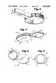
- FIG. 4 is a lower perspective view of yet another embodiment of the invention.
- FIG. 5 is a section view of FIG. 4.
- FIG. 6 is a lower perspective view of yet another embodiment of the invention.
- FIG. 7 is a perspective view of yet another embodiment of the invention.
- FIG. 8 is a bottom plan view of the invention as shown in FIG. 7 in its open position.
- FIG. 9 is a bottom plan view of the invention as shown in FIG. 7 in its closed position.
- FIG. 1 a side elevation schematic view of the invention shown generally at numeral 10 is there shown.
- the invention 10 shown in schematic as a section view includes a main body portion 14 having a concaved surface 12 and a back surface 16.
- the concaved lower surface 12 is reflective of light and heat waves and preferably is formed of a spherical section having a relatively short optical focal point at F.
- a pipe bowl B is shown in phantom which includes a central cavity C into which tobacco T is placed for smokable combustion.
- a zone designated generally as A typically represents the area of combustion of the upper portion of the tobacco T. Combustion of even a small portion of the tobacco T in zone A results in emission of light and infrared rays upward in the direction of the arrows (and in all other directions outwardly from the bowl cavity C).
- the reflected and focused rays at F are sufficient to effect combustion of the tobacco T.
- the focal point F is moved various places within zone A unlit tobacco in the entire zone A may be ignited.
- the preferred embodiment has dimensions of the reflective surface 12 equal to a radius of curvature of 50 mm having a focal length of 25 mm and an overall diameter of approximately 35 mm.
- the invention does not reflect all of the rays emitting from the burning tobacco, nonetheless a sufficient quantity of generally vertically emitting rays are reflected back by surface 12 to the focal point F so as to create a hot spot on the tobacco T sufficient to effect continued combustion and reignition as desired.
- FIG. 2 another embodiment of the invention is shown generally at numeral 20 formed of a rigid, disc-shaped member having serrations or knurling 24 along its perimeter.
- Reflective surface 22 is again a segment of a sphere.
- FIG. 3 yet another embodiment of the invention is shown generally at numeral 30, having a mirrored, reflective surface 32 formed as spherical segment.
- the perimeter 34 is formed having a transverse semi-circular section providing another contour of sufficient thickness to facilitate hand holding of the device 30 during use.
- FIG. 4 The embodiment of the invention in FIG. 4 shown generally at numeral 40 is provided for its thinness and may be adhered or molded onto a flat surface such as a book of matches or other more ornamental objects such as objects of jewelry and the like to enhance marketability.
- This embodiment 40 is generally circular having a transverse section as best seen in FIG. 5 similar to that of a fresnal lens.
- This embodiment 40 includes a mirrored, fresnal-type reflective surface shown generally at 42 having a series of concentric reflective surfaces beginning at the center portion 48 and outwardly extending in concentric reflective rings shown typically at 50 such that the rays upwardly emitting from the burning tobacco as shown in the direction of the upward arrows reflect from surface 42 back downwardly to a focal point (below FIG. 5) to effect ignition of the tobacco as previously described.
- FIG. 6 yet another embodiment of the invention is shown generally at 52 having a spherical-segment mirrored or reflective surface 54 and having spaced transverse ribs 56 around the perimeter of the rigid circular body for holdability.
- This embodiment 52 also includes a lateral or radially extending handle 58 which is provided so that the user's fingers are somewhat removed from the close proximity to the burning tobacco.
- handle 58 provides quick, easy minor rotational reorientation of this embodiment 52 in the direction of the arrow to more easily achieve tobacco ignition over the entire zone A of FIG. 1.
- FIGS. 7, 8 and 9 another embodiment of the invention is there shown generally at numeral 60 having a rigid disc-shaped member 62 which includes a spherical-segment reflective surface 66 as previously described. Knurling along its perimeter at 68 is also provided for ease of opening and closing.
- the reflective body 62 includes extension 70 which is pivotally connected by pin 78 to holder 64. Holder 64 is formed of two spaced, thin flat panels 72 and 74 which are held in fixed parallel relation by pins 76 and 78.
- the mirrored body 62 may be pivoted in the direction of the arrow in FIG. 8 from its open position for use about pin 78 to the protected, closed position as shown in FIG. 9.
- the mirrored surface 66 In a closed position, the mirrored surface 66 is thus protected by panels 72 and 74 from being scratched or dirtied.
- the reflective surface may be achieved by a number of well known techniques, including mirrored glass, highly polished silver-colored or gold-colored precious metals or the like
- the reflective surface of the preferred embodiment of the invention is formed by vacuum depositing a gold coating on the reflective surface. This gold coating increases the reflectivity of the reflective surface to between 95% and 98% with regard to infrared rays up to wave lengths about 15 microns. Energy waves in this spectrum carry the most energy of rays emanating from the burning pipe tobacco.
- Any convenient focal length may be selected so long as the reflected rays are sufficiently strong when focused atop the tobacco to effect combustion. However, a very short focal length, whereby the device is held in very close proximity above and generally parallel to the rim of the pipe bowl is preferred.
Abstract
A tobacco pipe combustion maintenance accessory for maintaining continuous burning of tobacco in the bowl of a pipe once the tobacco is initially ignited. The device includes a generally flat body having a curvilinear concave reflective surface on one side of the body. When the body is held above the pipe bowl, the curvilinear surface, properly positioned, reflects heat and light waves emitting from the portion of burning tobacco back at the tobacco in focused or concentrated form to ignite the unlit portions of the tobacco at the point where the reflective rays focus. By manipulation of the device in very close proximity above the rim of the pipe bowl so that the rays are reflected downardly into the tobacco, the collected rays at their point of focus maintain the tobacco burning. The curvilinear surface is preferably a spherical segment and may also be structured similar to a fresnal lens having reflective concentric surfaces to achieve relative flatness and a shorter focal length. A preferred gold-colored reflective surface improves performance by more efficiently reflecting infrared rays. Various structures for holding the device are also provided.
Description
This invention relates generally to tobacco pipes and more particularly to a device useful in maintaining continuous combustion of tobacco within the pipe.
Individuals who smoke tobacco using a tobacco pipe are well known to be required to exercise considerable diligence (fidgeting) in maintaining the tobacco in ignited condition until completely burned. Typically, the tobacco must be reignited several times to obtain the full combustion and satisfaction from each load of tobacco placed into the bowl of the pipe.
In addition to simply reigniting the tobacco, many users also use various well known devices including a book of matches and one's fingers to assist in obtaining a more conducive mixture of air flow and elevated temperature to maintain combustion.
In fact, it has been acknowledged by a retail sales tobacconist that the single most important acknowledged reason that pipe smokers discontinue their use is because of the difficulty in maintaining combustion during the entire burning life of the tobacco within the bowl.
One patented device known to applicant is disclosed in U.S. Pat. No. 3,709,233 to Stelitano which teaches a tobacco pipe construction which provides a small opening through which the tobacco is ignited, after which a sliding cover may be utilized, in part, to facilitate continuous tobacco combustion.
Two other patented devices are also known to applicant. U.S. Pat. No. 3,117,579 to Alsafrana discloses a uniquely structured pipe having a pivotal side portion through which the tobacco is placed into the bowl. The tobacco pipe invented by Hefti as disclosed in U.S. Pat. No. 3,106,922 includes a pivotal end plate for containing the tobacco within the bowl and having a mesh portion which helps to regulate air flow.
The present invention provides an easily positionable accessory which may be manipulated by hand directly above the tobacco burning within a conventional pipe bowl after the tobacco is initially ignited. The device, when properly positioned and manipulated, reflects and focuses light and heat waves emitting from the partially burning tobacco back into the bowl in focused fashion so as to ignite (or reignite) unlit portions of the tobacco.
This invention is directed to a tobacco pipe combustion maintenance accessory for maintaining continuous burning of tobacco in the bowl of a pipe once the tobacco is initially ignited. The device includes a generally flat body having a curvilinear concave reflective surface on one side of the body. When the body is held above the pipe bowl, the curvilinear surface, properly positioned, reflects heat and light waves emitting from the portion of burning tobacco back at the tobacco in focused or concentrated form to ignite the unlit portions of the tobacco at the point where the reflective rays focus. By manipulation of the device in very close proximity above the rim of the pipe bowl so that the rays are reflected downwardly into the tobacco, the collected rays at their point of focus maintain the tobacco burning. The curvilinear surface is preferably a spherical segment and may also be structured similar to a fresnal lens having reflective concentric surfaces to achieve relative flatness and a shorter focal length. A preferred gold-colored reflective surface improves performance by more efficiently reflecting infrared rays. Various structures for holding the device are also provided.
It is therefore an object of this invention to provide an accessory for tobacco pipe users to assist in maintaining continuous combustion of tobacco until completely burned.
It is another object of this invention to provide an easily manipulable accessory for maintaining pipe tobacco combustion.
It is yet another object to provide the above invention in a wide range of decorative forms to satisfy the broadest aesthetic range of pipe tobacco smokers.
In accordance with these and other objects which will become apparent hereinafter, the instant invention will now be described with reference to the accompanying drawings.
FIG. 1 is a side elevation schematic view of the invention in operation above the bowl of a conventional tobacco pipe shown in phantom.
FIG. 2 is a lower perspective view of one embodiment of the invention.
FIG. 3 is a lower perspective view of another embodiment of the invention.
FIG. 4 is a lower perspective view of yet another embodiment of the invention.
FIG. 5 is a section view of FIG. 4.
FIG. 6 is a lower perspective view of yet another embodiment of the invention.
FIG. 7 is a perspective view of yet another embodiment of the invention.
FIG. 8 is a bottom plan view of the invention as shown in FIG. 7 in its open position.
FIG. 9 is a bottom plan view of the invention as shown in FIG. 7 in its closed position.
Referring now to the drawings, and particularly to FIG. 1, a side elevation schematic view of the invention shown generally at numeral 10 is there shown. The invention 10 shown in schematic as a section view, includes a main body portion 14 having a concaved surface 12 and a back surface 16. The concaved lower surface 12 is reflective of light and heat waves and preferably is formed of a spherical section having a relatively short optical focal point at F. A pipe bowl B is shown in phantom which includes a central cavity C into which tobacco T is placed for smokable combustion.
During combustion of the tobacco T, a zone designated generally as A typically represents the area of combustion of the upper portion of the tobacco T. Combustion of even a small portion of the tobacco T in zone A results in emission of light and infrared rays upward in the direction of the arrows (and in all other directions outwardly from the bowl cavity C).
These light and infrared rays upwardly emitting from the combustion zone A strike and then downwardly reflect from the reflective surface 12 in the direction of the arrows to a focal point F. It is this focusing of these light and infrared rays at F which facilitates the recombustion or new combustion of unlit tobacco T in the zone A.
Thus by holding the device 10 at a proper distance above the pipe bowl B such that focal point F falls generally within zone A, the reflected and focused rays at F are sufficient to effect combustion of the tobacco T. By continued minor repositioning of the device 10 so that the focal point F is moved various places within zone A unlit tobacco in the entire zone A may be ignited. Once familiar with moving the device 10 to adjust the position of the focal point F both laterally (or angularly) and vertically, it is routinely possible to insure continuous combustion of all of the tobacco T once the initial ignition is effected.
The preferred embodiment has dimensions of the reflective surface 12 equal to a radius of curvature of 50 mm having a focal length of 25 mm and an overall diameter of approximately 35 mm.
It is here noted that, although the invention does not reflect all of the rays emitting from the burning tobacco, nonetheless a sufficient quantity of generally vertically emitting rays are reflected back by surface 12 to the focal point F so as to create a hot spot on the tobacco T sufficient to effect continued combustion and reignition as desired.
Referring now to FIG. 2, another embodiment of the invention is shown generally at numeral 20 formed of a rigid, disc-shaped member having serrations or knurling 24 along its perimeter. Reflective surface 22 is again a segment of a sphere.
Referring now to FIG. 3, yet another embodiment of the invention is shown generally at numeral 30, having a mirrored, reflective surface 32 formed as spherical segment. In this embodiment 30 the perimeter 34 is formed having a transverse semi-circular section providing another contour of sufficient thickness to facilitate hand holding of the device 30 during use.
The embodiment of the invention in FIG. 4 shown generally at numeral 40 is provided for its thinness and may be adhered or molded onto a flat surface such as a book of matches or other more ornamental objects such as objects of jewelry and the like to enhance marketability. This embodiment 40 is generally circular having a transverse section as best seen in FIG. 5 similar to that of a fresnal lens. This embodiment 40 includes a mirrored, fresnal-type reflective surface shown generally at 42 having a series of concentric reflective surfaces beginning at the center portion 48 and outwardly extending in concentric reflective rings shown typically at 50 such that the rays upwardly emitting from the burning tobacco as shown in the direction of the upward arrows reflect from surface 42 back downwardly to a focal point (below FIG. 5) to effect ignition of the tobacco as previously described.
Referring now to FIG. 6, yet another embodiment of the invention is shown generally at 52 having a spherical-segment mirrored or reflective surface 54 and having spaced transverse ribs 56 around the perimeter of the rigid circular body for holdability. This embodiment 52 also includes a lateral or radially extending handle 58 which is provided so that the user's fingers are somewhat removed from the close proximity to the burning tobacco. However, handle 58 provides quick, easy minor rotational reorientation of this embodiment 52 in the direction of the arrow to more easily achieve tobacco ignition over the entire zone A of FIG. 1.
Referring lastly to FIGS. 7, 8 and 9, another embodiment of the invention is there shown generally at numeral 60 having a rigid disc-shaped member 62 which includes a spherical-segment reflective surface 66 as previously described. Knurling along its perimeter at 68 is also provided for ease of opening and closing. The reflective body 62 includes extension 70 which is pivotally connected by pin 78 to holder 64. Holder 64 is formed of two spaced, thin flat panels 72 and 74 which are held in fixed parallel relation by pins 76 and 78.
Thus, as best seen in FIG. 8 and 9, the mirrored body 62 may be pivoted in the direction of the arrow in FIG. 8 from its open position for use about pin 78 to the protected, closed position as shown in FIG. 9. In a closed position, the mirrored surface 66 is thus protected by panels 72 and 74 from being scratched or dirtied.
Although the reflective surface may be achieved by a number of well known techniques, including mirrored glass, highly polished silver-colored or gold-colored precious metals or the like, the reflective surface of the preferred embodiment of the invention is formed by vacuum depositing a gold coating on the reflective surface. This gold coating increases the reflectivity of the reflective surface to between 95% and 98% with regard to infrared rays up to wave lengths about 15 microns. Energy waves in this spectrum carry the most energy of rays emanating from the burning pipe tobacco.
Any convenient focal length may be selected so long as the reflected rays are sufficiently strong when focused atop the tobacco to effect combustion. However, a very short focal length, whereby the device is held in very close proximity above and generally parallel to the rim of the pipe bowl is preferred.
While the instant invention has been shown and described herein in what are conceived to be the most practical and preferred embodiments, it is recognized that departures may be made therefrom within the scope of the invention, which is therefore not to be limited to the details disclosed herein, but is to be afforded the full scope of the claims so as to embrace any and all equivalent apparatus and articles.
Claims (8)
1. A tobacco pipe combustion maintenance device for maintaining continuous burning of once-ignited tobacco in the bowl of a tobacco pipe, said device comprising:
a body having a curvilinear concaved reflective surface on one side of said body;
said body suitably sized and having hand gripping means for adjustably positioning said body above the pipe bowl with said reflective surface facing downwardly into the bowl;
said reflective surface structured to reflect and focus light and heat waves emanating from burning portions of the tobacco within the bowl back to ignite unlit portions of the tobacco when the device is positioned directly above the bowl;
said reflective surface having a focal length sized to ignite the unlit portions of the tobacco when said body is positioned in very close proximity directly above the rim of the bowl.
2. A tobacco pipe combustion device as set forth in claim 1, wherein:
said reflective surface is a spherical segment;
said body is disc shaped having a generally flat upper surface.
3. A tobacco pipe combustion device as set forth in claim 2, further comprising:
a gold-colored layer deposited on said reflective surface whereby infrared rays emanating from the burning portion of the tobacco are more fully reflected downwardly for use.
4. A tobacco pipe combustion device as set forth in claim 1, further comprising:
knurling formed into the perimeter of said body for enhanced holdability of said device during use.
5. A tobacco pipe combustion device as set forth in claim 1, further comprising:
a holder having spaced, parallel panels;
said body generally flattened and pivotally connected between said panels adjacent a common margin of said panels and said body whereby said body may be pivoted from a first position to a second position with respect to said panel;
said body fully between and protectably concealed by said panels when said body is in its first position;
said body extending from said panels and said panels serving as a handle for said body when said body is in its second position during use.
6. A tobacco pipe combustion maintenance device for maintaining continuous burning of once-ignited tobacco in the bowl of a tobacco pipe, said device comprising:
a body having a curvilinear concaved reflective surface on one side of said body;
said body suitably sized and having hand gripping means for adjustably positioning said body above the pipe bowl with said reflective surface facing downwardly into the bowl;
said reflective surface structured to reflect and focus light and heat waves emanating from burning portions of the tobacco within the bowl back to ignite unlit portions of the tobacco when the device is positioned directly above the bowl; and
an elongated, slender handle extending radially outwardly from a perimeter point of said body, said handle generally coplaner with said reflective surface.
7. A tobacco pipe combustion device as set forth in claim 8, further comprising:
a gold-colored layer deposited on said reflective surface whereby infrared rays emanating from the burning portion of the tobacco are more fully reflected downwardly for use.
8. A tobacco pipe combustion maintenance device for maintaining continuous burning of once-ignited tobacco in the bowl of a tobacco pipe, said device comprising:
a body having a curvilinear concaved reflective surface on one side of said body;
said body suitably sized and having hand gripping means for adjustably positioning said body above the pipe bowl with said reflective surface facing downwardly into the bowl;
said reflective surface structured to reflect and focus light and heat waves emanating from burning portions of the tobacco within the bowl back to ignite unlit portions of the tobacco when the device is positioned directly above the bowl;
said body having a flattened shape similar to a generally fresnal lens and having a plurality of concentric reflective rings collectively forming said reflector surface.
Priority Applications (1)
| Application Number | Priority Date | Filing Date | Title |
|---|---|---|---|
| US07/419,898 US4934384A (en) | 1989-10-11 | 1989-10-11 | Tobacco pipe combustion accessory |
Applications Claiming Priority (1)
| Application Number | Priority Date | Filing Date | Title |
|---|---|---|---|
| US07/419,898 US4934384A (en) | 1989-10-11 | 1989-10-11 | Tobacco pipe combustion accessory |
Publications (1)
| Publication Number | Publication Date |
|---|---|
| US4934384A true US4934384A (en) | 1990-06-19 |
Family
ID=23664203
Family Applications (1)
| Application Number | Title | Priority Date | Filing Date |
|---|---|---|---|
| US07/419,898 Expired - Fee Related US4934384A (en) | 1989-10-11 | 1989-10-11 | Tobacco pipe combustion accessory |
Country Status (1)
| Country | Link |
|---|---|
| US (1) | US4934384A (en) |
Cited By (3)
| Publication number | Priority date | Publication date | Assignee | Title |
|---|---|---|---|---|
| US5526758A (en) * | 1994-11-02 | 1996-06-18 | The Babcock & Wilcox Company | Distribution cone for pulverized coal burners |
| US6644303B1 (en) * | 2002-08-08 | 2003-11-11 | Keith Worthington | Solar lighter for a smoking instrument |
| US20070169783A1 (en) * | 2006-01-20 | 2007-07-26 | Joe Santos | Belt buckle solar cigarette lighter |
Citations (1)
| Publication number | Priority date | Publication date | Assignee | Title |
|---|---|---|---|---|
| US1349276A (en) * | 1919-09-27 | 1920-08-10 | Harry J Hays | Tobacco-pipe |
-
1989
- 1989-10-11 US US07/419,898 patent/US4934384A/en not_active Expired - Fee Related
Patent Citations (1)
| Publication number | Priority date | Publication date | Assignee | Title |
|---|---|---|---|---|
| US1349276A (en) * | 1919-09-27 | 1920-08-10 | Harry J Hays | Tobacco-pipe |
Cited By (3)
| Publication number | Priority date | Publication date | Assignee | Title |
|---|---|---|---|---|
| US5526758A (en) * | 1994-11-02 | 1996-06-18 | The Babcock & Wilcox Company | Distribution cone for pulverized coal burners |
| US6644303B1 (en) * | 2002-08-08 | 2003-11-11 | Keith Worthington | Solar lighter for a smoking instrument |
| US20070169783A1 (en) * | 2006-01-20 | 2007-07-26 | Joe Santos | Belt buckle solar cigarette lighter |
Similar Documents
| Publication | Publication Date | Title |
|---|---|---|
| JP3014335U (en) | Flame lighter | |
| US4218894A (en) | Pierced earring with adjustable ornament | |
| US4934384A (en) | Tobacco pipe combustion accessory | |
| US6405441B1 (en) | Wick trimmer and capture device | |
| US8568135B2 (en) | Device for lighting and extinguishing candles | |
| KR200268993Y1 (en) | Stove device for a portable burner | |
| US6607377B2 (en) | Candle holder for mounting on a support | |
| JP4287612B2 (en) | Safety lighter with multiple finger pads | |
| US20030031969A1 (en) | Piezoelectric jet lighter for cigarette, cigar and pipe | |
| US4522583A (en) | Cigarette lighter | |
| US5537989A (en) | Candle wick extracting and positioning device and method | |
| CN108451386A (en) | A kind of smokeless fuel baking oven | |
| US4610240A (en) | Solar lighter | |
| US20070169783A1 (en) | Belt buckle solar cigarette lighter | |
| US6270339B1 (en) | Prayer candle device | |
| USD383029S (en) | Multipurpose outdoor fire pit | |
| US3344266A (en) | Smoker s lighter reflector means | |
| NZ308130A (en) | Gas lighter has safety device in the form of a knurled wheel moved by a smooth surfaced carrier | |
| US6093016A (en) | Cigarette lighter in the shape of a statue | |
| US6769904B1 (en) | Candle snuffer and method of use | |
| USRE31316E (en) | Elongated igniting device | |
| US7255455B2 (en) | Candle extinguisher and a method for producing a candle extinguisher | |
| US20030217756A1 (en) | Cigarette lighter | |
| US20030134243A1 (en) | Smokeless candle snuffer and wick trimmer combination | |
| US20240011633A1 (en) | Cigar lighter with enclosed burn area |
Legal Events
| Date | Code | Title | Description |
|---|---|---|---|
| REMI | Maintenance fee reminder mailed | ||
| FPAY | Fee payment |
Year of fee payment: 4 |
|
| SULP | Surcharge for late payment | ||
| FEPP | Fee payment procedure |
Free format text: PAYOR NUMBER ASSIGNED (ORIGINAL EVENT CODE: ASPN); ENTITY STATUS OF PATENT OWNER: SMALL ENTITY |
|
| REMI | Maintenance fee reminder mailed | ||
| LAPS | Lapse for failure to pay maintenance fees | ||
| FP | Lapsed due to failure to pay maintenance fee |
Effective date: 19980624 |
|
| STCH | Information on status: patent discontinuation |
Free format text: PATENT EXPIRED DUE TO NONPAYMENT OF MAINTENANCE FEES UNDER 37 CFR 1.362 |