US4927329A - Aircraft engine unducted fan blade pitch control system - Google Patents
Aircraft engine unducted fan blade pitch control system Download PDFInfo
- Publication number
- US4927329A US4927329A US07/260,645 US26064588A US4927329A US 4927329 A US4927329 A US 4927329A US 26064588 A US26064588 A US 26064588A US 4927329 A US4927329 A US 4927329A
- Authority
- US
- United States
- Prior art keywords
- power
- motors
- bus
- motor
- coupled
- Prior art date
- Legal status (The legal status is an assumption and is not a legal conclusion. Google has not performed a legal analysis and makes no representation as to the accuracy of the status listed.)
- Expired - Fee Related
Links
Images

Classifications
-
- F—MECHANICAL ENGINEERING; LIGHTING; HEATING; WEAPONS; BLASTING
- F02—COMBUSTION ENGINES; HOT-GAS OR COMBUSTION-PRODUCT ENGINE PLANTS
- F02K—JET-PROPULSION PLANTS
- F02K3/00—Plants including a gas turbine driving a compressor or a ducted fan
- F02K3/02—Plants including a gas turbine driving a compressor or a ducted fan in which part of the working fluid by-passes the turbine and combustion chamber
- F02K3/04—Plants including a gas turbine driving a compressor or a ducted fan in which part of the working fluid by-passes the turbine and combustion chamber the plant including ducted fans, i.e. fans with high volume, low pressure outputs, for augmenting the jet thrust, e.g. of double-flow type
- F02K3/062—Plants including a gas turbine driving a compressor or a ducted fan in which part of the working fluid by-passes the turbine and combustion chamber the plant including ducted fans, i.e. fans with high volume, low pressure outputs, for augmenting the jet thrust, e.g. of double-flow type with aft fan
-
- B—PERFORMING OPERATIONS; TRANSPORTING
- B64—AIRCRAFT; AVIATION; COSMONAUTICS
- B64C—AEROPLANES; HELICOPTERS
- B64C11/00—Propellers, e.g. of ducted type; Features common to propellers and rotors for rotorcraft
- B64C11/30—Blade pitch-changing mechanisms
- B64C11/44—Blade pitch-changing mechanisms electric
-
- B—PERFORMING OPERATIONS; TRANSPORTING
- B64—AIRCRAFT; AVIATION; COSMONAUTICS
- B64D—EQUIPMENT FOR FITTING IN OR TO AIRCRAFT; FLIGHT SUITS; PARACHUTES; ARRANGEMENT OR MOUNTING OF POWER PLANTS OR PROPULSION TRANSMISSIONS IN AIRCRAFT
- B64D41/00—Power installations for auxiliary purposes
-
- F—MECHANICAL ENGINEERING; LIGHTING; HEATING; WEAPONS; BLASTING
- F01—MACHINES OR ENGINES IN GENERAL; ENGINE PLANTS IN GENERAL; STEAM ENGINES
- F01D—NON-POSITIVE DISPLACEMENT MACHINES OR ENGINES, e.g. STEAM TURBINES
- F01D7/00—Rotors with blades adjustable in operation; Control thereof
-
- B—PERFORMING OPERATIONS; TRANSPORTING
- B64—AIRCRAFT; AVIATION; COSMONAUTICS
- B64D—EQUIPMENT FOR FITTING IN OR TO AIRCRAFT; FLIGHT SUITS; PARACHUTES; ARRANGEMENT OR MOUNTING OF POWER PLANTS OR PROPULSION TRANSMISSIONS IN AIRCRAFT
- B64D27/00—Arrangement or mounting of power plants in aircraft; Aircraft characterised by the type or position of power plants
- B64D2027/005—Aircraft with an unducted turbofan comprising contra-rotating rotors, e.g. contra-rotating open rotors [CROR]
-
- B—PERFORMING OPERATIONS; TRANSPORTING
- B64—AIRCRAFT; AVIATION; COSMONAUTICS
- B64D—EQUIPMENT FOR FITTING IN OR TO AIRCRAFT; FLIGHT SUITS; PARACHUTES; ARRANGEMENT OR MOUNTING OF POWER PLANTS OR PROPULSION TRANSMISSIONS IN AIRCRAFT
- B64D2221/00—Electric power distribution systems onboard aircraft
-
- F—MECHANICAL ENGINEERING; LIGHTING; HEATING; WEAPONS; BLASTING
- F05—INDEXING SCHEMES RELATING TO ENGINES OR PUMPS IN VARIOUS SUBCLASSES OF CLASSES F01-F04
- F05D—INDEXING SCHEME FOR ASPECTS RELATING TO NON-POSITIVE-DISPLACEMENT MACHINES OR ENGINES, GAS-TURBINES OR JET-PROPULSION PLANTS
- F05D2260/00—Function
- F05D2260/70—Adjusting of angle of incidence or attack of rotating blades
- F05D2260/74—Adjusting of angle of incidence or attack of rotating blades by turning around an axis perpendicular the rotor centre line
-
- F—MECHANICAL ENGINEERING; LIGHTING; HEATING; WEAPONS; BLASTING
- F05—INDEXING SCHEMES RELATING TO ENGINES OR PUMPS IN VARIOUS SUBCLASSES OF CLASSES F01-F04
- F05D—INDEXING SCHEME FOR ASPECTS RELATING TO NON-POSITIVE-DISPLACEMENT MACHINES OR ENGINES, GAS-TURBINES OR JET-PROPULSION PLANTS
- F05D2260/00—Function
- F05D2260/70—Adjusting of angle of incidence or attack of rotating blades
- F05D2260/76—Adjusting of angle of incidence or attack of rotating blades the adjusting mechanism using auxiliary power sources
-
- Y—GENERAL TAGGING OF NEW TECHNOLOGICAL DEVELOPMENTS; GENERAL TAGGING OF CROSS-SECTIONAL TECHNOLOGIES SPANNING OVER SEVERAL SECTIONS OF THE IPC; TECHNICAL SUBJECTS COVERED BY FORMER USPC CROSS-REFERENCE ART COLLECTIONS [XRACs] AND DIGESTS
- Y02—TECHNOLOGIES OR APPLICATIONS FOR MITIGATION OR ADAPTATION AGAINST CLIMATE CHANGE
- Y02T—CLIMATE CHANGE MITIGATION TECHNOLOGIES RELATED TO TRANSPORTATION
- Y02T50/00—Aeronautics or air transport
- Y02T50/60—Efficient propulsion technologies, e.g. for aircraft
Definitions
- This invention relates generally to systems for varying or controlling the pitch of propulsor blades of aircraft gas turbine engines and, more particularly, to an electric motor driven control apparatus for varying the pitch of fan blades of an unducted fan type gas turbine engine.
- Gas turbine engines generally include a gas generator which comprises a compressor for compressing air flowing rearward through the engine, a combustor in which fuel is mixed with the compressed air and ignited to form a high energy gas stream, and a turbine driven by the gas stream and connected to drive a rotor which in turn drives the compressor.
- Many engines further include a second turbine, known as a power turbine, located aft of the gas generator for extracting energy from the gas stream to drive a rotating load with variable pitch blades such as found in the propulsor of helicopters, ducted turbo-fan engines, and turbo-prop engines.
- the unducted fan engine such as is disclosed in U.K. Patent Application No. 2,129,502 published May 16, 1984.
- the power turbine includes counterrotating rotors and turbine blades which drive counterrotating unducted fan blades located radially outward of the power turbine section of the engine.
- the fan blades of the unducted fan engine are variable pitch blades to achieve optimum performance of the engine and thrust reversal. During operation, fuel efficiency of the engine can be optimized by varying the pitch of the blade to correspond to specific operating conditions.
- the actuating mechanism for controlling blade pitch utilize hydraulic actuators driving various types of gear arrangements to position the fan blades at desired locations or pitch angles.
- An exemplary form of pitch drive mechanism is illustrated in Wakeman et al. U.S. Pat. No. 4,657,484, issued Apr. 14, 1987 and assigned to the instant assignee, wherein the pitch of the fan blades is varied by a hydraulic actuator mounted inside the static power turbine support structure. The motion commanded from the actuator is first transmitted to the rotating member by a system of bearings and then to the blades by a system of gears and linkages mounted on the rotating member.
- Prior art systems which have relied on hydraulic controls for accurately positioning blade pitch sometimes function less than optimally in achieving the precision and bandwidth necessary to perform all of the control functions simultaneously. Furthermore, it has not been practical to provide back-up or alternate sources of hydraulic power to support the pitch control mechanism in case of failure of the primary system. Such failure thus requires shut-down of the pitch control system and default to a fixed emergency condition. Still further, it is believed that the hydraulic system efficiency is typically rather low, and it is desirable to increase efficiency of such system in order to improve specific fuel consumption, reduce peak demand and reduce the thermal load of the engine.
- the hydraulic motors are proportionately controlled by a small electrically operated pilot valve controlling the main control valve for the hydraulics.
- a variable swash plate may be used in the hydraulic motor to replace or supplement the power valve.
- the swash plate may be operated by an electric or hydraulic proportional actuator.
- a single hydraulic pump operating from the engine powers both of the hydraulic motors. It is not believed practical to extend the hydraulic system beyond the engine envelope to achieve power source redundancy and a second full system or hydraulic pump requires an unacceptable weight penalty.
- One object of the present invention is to provide an improved apparatus and system for controlling the pitch of propulsor blades in an unducted fan aircraft gas turbine engine which overcomes the above discussed disadvantages, or undesirable features, of the prior art.
- Another object of the invention is to provide a control system for regulating blade pitch which is relatively light in weight, reliable, and operable from electrical power generated within the engine.
- a further object of the invention is to provide an electrically powered blade pitch control system which includes redundant devices for improving reliability.
- propulsion means for a conveyance such as an aircraft, comprises a gas turbine engine having a stationary member, and first and second rotating members coaxially disposed about the stationary member.
- An annular gas flow path coaxial with the first and second rotating members is intersected by a plurality of first and second rotor blades attached to the first and second rotating members, respectively, which extend into the flow paths such that the gas stream through the flow path causes the first and second rotating members to counterrotate.
- a plurality of forward and aft variable pitch propulsor blades are coupled to, and disposed radially outward of, the first and second rotating members. Operation of gear means coupled to the propulsor blades allows the pitch angle of the propulsor blades to be varied.
- Electric motor means are connected to the stationary member and include a rotor driving a shaft coupled to the gear means such that rotation of the motor shaft effects a pitch change of the propulsor blades.
- the gas turbine engine generates the gas stream, and includes a rotating compressor shaft.
- Alternator means are coupled to the compressor shaft for generating variable frequency, variable voltage, unregulated alternating current power.
- a rectifier connected to the alternator means converts the alternating current power to direct current power and an inverter connected for receiving the direct current power converts the direct current power to controlled frequency, controlled amplitude alternating current power.
- the output of the converter selectively supplies the controlled alternating current power to the motor.
- Control means responsive to a desired propulsor pitch command controls the inverter means for driving the blades to a desired pitch.
- two electric motors are provided, each connected through corresponding gears to drive a gear mechanism, respectively, which is in driving relationship with a corresponding respective one of the forward and aft propulsor blades.
- the inverter includes two inverter sections connected, respectively, to the first and second motors, and the control means controls each of the inverter for independently positioning each respective forward and aft set of propulsor blades.
- additional electric motors may be coupled to each of the first and second gear mechanisms, respectively, with each of the additional electric motors being powered by corresponding inverters coupled to the common power bus.
- the redundant system may also include dual alternators connected to the compressor drive shaft with dual rectifiers connected respectively to each of the alternators for supplying power from a corresponding alternator to the common power bus.
- the common power bus may be coupled to the aircraft electrical power system whereby the aircraft may supply electrical power to the power bus upon failure of the alternator.
- the engines of the aircraft may be connected to the common power bus so that failure of the alternator system in one engine can be overcome by drawing power from the alternator system of another engine.
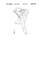
- FIG. 1 illustrates an aircraft having gas turbine engines with counterrotating fore and aft propellers
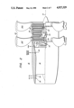
- FIG. 2 is a simplified and partially cut-away cross-sectional view of one of the aircraft engines of FIG. 1 with a hydraulic pitch control mechanism, coupled to propulsor means driven by the engine;
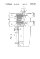
- FIG. 3 is a simplified and partially cut-away cross-sectional view of one of the aircraft engines of FIG. 1 with an electrically-operated pitch control mechanism, in accordance with the present invention, coupled to propulsor means driven by the engine;
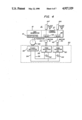
- FIG. 4 is a simplified schematic/block diagram of one embodiment of an electrically-operated pitch control system employed in conjunction with a gas turbine engine according to the present invention
- FIG. 5 is a simplified schematic/block diagram of another embodiment of an electrically-operated pitch control system employed in conjunction with a gas turbine engine according to the present invention
- FIG. 6 is a simplified schematic/block diagram of still another embodiment of an electrically-operated pitch control system employed in conjunction with a gas turbine engine according to the present invention.
- FIG. 7 is a block diagram of a control system for electric motors used in the embodiments shown in FIGS. 4-6.
- FIG. 1 illustrates an aircraft 10 having engines 12 of the gas turbine type mounted on the airframe near the tail end thereof.
- Engines 12 each drive a fore propulsor 14F and an aft propulsor 14A which rotate in opposite directions about a propeller axis 16.
- FIG. 2 illustrates in greater detail the engine propulsor system 12 of FIG. 1 which employs hydraulic actuators for pitch change.
- Ahead (or forward) of propulsors 14A and 14F is gas turbine 18 such as type F404 manufactured by the assignee of the present invention.
- the gas turbine drives a shaft (not shown) and also can be considered to be a gas generator since it generates a high energy gas stream, represented by an arrow 20, that is supplied to a propulsor stage 22.
- Propulsor stage 22 extracts energy from the gas stream directly by means of low-speed counterrotating power turbine blade sets. This technique obviates any need for using a high speed turbine, thereby avoiding any need for employing a speed reduction gearbox in order to drive the propulsor.
- a first set of blades 24 extracts energy from the gas stream indicated by arrow 20 and spins the forward propulsor 14F in one direction.
- a second set of blades 26 also extracts energy from the gas stream but spins the aft propulsor 14A in the opposite direction.
- Bearings 28 support the blade sets and propulsors and allow this counterrotation.
- a pitch-change mechanism 30 for changing pitch of propulsors 14A and 14F is shown schematically. It is desirable to control pitch-change mechanism 30 so that the propulsor pitch is proper under the prevailing operating conditions of the aircraft.
- Various monitors are located in gas turbine 18 including sensors 32, 34 which provide signals representative of gas pressure (p2, P46) and sensor 36 which provides signals representative of inlet air temperature (T2).
- Signal P2 (inlet air pressure) and signal P46 (air pressure exiting gas generator 18) are used to develop engine pressure ratio (EPR). While EPR is known to be the ratio P46/P2, it will be appreciated that if P2 is held constant, EPR can be obtained directly from a measurement of P46.
- Rotor speed is also sensed by a monitor 38 and provided as a control signal from gas turbine 18.
- FIG. 3 is a drawing which generally corresponds to the system shown in FIG. 2, an important exception, however, being that the hydraulic actuators have been replaced by electrically-operated actuators.
- an alternator 40 is positioned in the gas generator adjacent the compressor stage (not shown) and is driven by a driven shaft (not shown) in gas generator 18 coupled to the compressor for producing variable frequency, variable amplitude, unregulated alternating current (AC).
- AC alternating current
- Motors 42 and 44 are fixedly mounted so as not to rotate with the sump and are preferably alternating current electric motors since the sump, which contains lubricating oil on its interior surface surrounding a core of oil vapor, does not present a hospitable environment to direct current or DC motors which require brushes and commutators and inherently generate sparks during commutation.
- Each of motors 42 and 44 is mechanically coupled to a corresponding gear box 46 and 48, respectively, which is in turn coupled to the mechanism controlling the pitch of propulsors 14A and 14F, respectively.
- the motors are stationary with respect to the rotating propulsors.
- Gear boxes 46 and 48 each provide a mechanical advantage sufficient to prevent forces on the propulsor blades, due to air flow impinging thereon, from repositioning motors 42 and 44, respectively.
- Power from alternator 40 is supplied through a rectifier and inverter stage 50 to motors 42 and 44.
- FIG. 4 is a schematic representation of the present invention as applied to the gas turbine engine illustrated in FIG. 3.
- Alternator 40 is coupled through gearing or other appropriate power take-off devices at a mounting pad 41 to gas generator 18. It will be appreciated that the driven shaft of the gas generator is turning at a much lower rate than is normally desired to rotate the alternator and therefore apparatus 41 is utilized to increase the rotational speed of the alternator.
- a power turbine 27, which comprises power turbine blades 24 and 26, shown in FIG. 3, is driven by gas generator 18.
- Each of motors 42 and 44 is connected through appropriate gearing arrangements 46 and 48, respectively, to control pitch of the respective one of rotating blade rows 14A and 14F.
- Each of motors 42 and 44 includes a rotatable rotor mounted on a driven shaft which, in turn, drives the respective one of gear means 46 and 48.
- the shafts of alternator 40 and motors 42 and 44, and the couplings to blade rows 14A and 14F, are indicated by dashed lines extending to their associated gear arrangements.
- a rectifier inverter system 50 provided for this purpose includes a fixed rectifier 52 electrically connected to alternator 40 for converting the AC power to DC power and coupling that power to a power bus indicated by lines 54 and 56.
- the DC power on the power bus is supplied to first and second inverters 58 and 60, respectively, which operate to apply AC power of desired characteristics to motors 44 and 42, respectively.
- inverters 58 and 60 comprise pulse width modulated (PWM) inverters of a type well known in the art and described, for example, in S.C. Peak et al., "A Study of System Losses In A Transistorized Inverter-Induction Motor Drive System", IEEE Transactions On Industry Applications, Jan/Feb 1985, Vol. IA-21, No. 1, pp. 248-258 and J. L. Oldenkamp et al., "Selection and Design Of An Inverter-Driven Induction Motor For A Traction Drive System", IEEE Transactions On Industry Applications, Jan/Feb 1985, Vol. IA-21, No. 1, pp. 259-265.
- PWM pulse width modulated
- Capacitors 62 and 64 are typically connected across the DC power bus at the input of the PWM inverters 58 and 60, respectively, to minimize line current fluctuations.
- the frequency variation in power supplied by alternator 40 is compensated for by fixed rectifier 52.
- the voltage variation in the power supplied from the rectifier is accommodated by pulse width modulation in the individual inverters 58 and 60.
- a single alternator is utilized to supply electrical power to each of a pair of motors 42 and 44 which control the pitch angles of propulsor blades in each of the fan blade rows, respectively.
- motors 42 and 44 be permanent magnet AC motors in order to achieve high efficiency without excessive weight.
- the permanent magnet motor having independent flux excitation, is desirable in the event power is lost from the inverter circuit, since power may then be extracted from the rotation of the blade system to change the blade pitch angles so as to move the blades into the feathered position at an emergency default.
- induction or switched reluctance motors may be used in a similar arrangement, such motors require a fully operational inverter for default performance in case of inverter power loss.
- the system of FIG. 4 when utilizing permanent magnet AC motors, achieves the benefits of high efficiency, wide bandwidth and high peak demand capability.
- FIG. 5 shows a modification of the system of FIG. 4 in which redundancy is added in order to protect against loss of blade pitch control in the event one component of the system should fail.
- the system of FIG. 5 employs two independent alternators 40A and 40B connected to a common power take-off shaft 43 although, as an alternative, the alternators may be connected to independent shafts from gas generator 18 (shown in FIG. 4).
- Each of alternators 40A and 40B is connected to a separate fixed rectifier circuit 52A and 52B, respectively, which in turn supply power from the alternators to the common DC bus illustrated by lines 54 and 56.
- Each of motors 42 and 44 is, in this embodiment, formed of separate motor sections 42A, 42B and 44A, 44B, respectively.
- the motor sections may be separate, independent motors, but preferably formed in common housings, with separated windings, and with rotors mounted on a common shaft.
- Each of motors 42A, 42B and 44A, 44B is powered from an independent PWM inverter 60A, 60B and 58A, 58B, respectively.
- Each of the inverters is connected to the common DC bus 54 and 56. Consequently, if any of the pitch change motors or inverters or one of the alternators or rectifiers fails, operation of the system may be continued at a safe level with the remaining components. In the preferred embodiment, where each motor is split into two sections mounted on a common shaft, the penalty for this redundancy is only about 15% added weight.
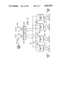
- FIG. 6 illustrates a modification of the system of FIG. 5 which provides an alternate way of structuring a fault tolerant system to take advantage of a variety of power sources in an emergency.
- the power sources from multiple engines of the aircraft are cross coupled so that the alternator of one engine can supply power not only to that one engine, but also to another of the engines through a fixed rectifier 75, when an alternator shaft or winding fails or if a rectifier 52 fails.
- the aircraft power bus which normally operates at 400 Hz, can be coupled into the common DC bus simply by rectifying the 400 Hz AC power.
- engine 1 and its associated power system is connected to two power busses 54, 56 and 54A, 56A, respectively, and similarly, engine 2 and its associated power system is connected to the two busses.
- Each of the busses is also connected to the aircraft 400 Hz power system through corresponding rectifiers 66 and 68.
- Battery power is supplied to the busses through isolating diodes 69 and 71.
- the rotational motion of the propulsors may be utilized to drive motors 42 and 44 in a regenerative mode so as to derive power from the engine.
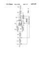
- FIG. 7 is a block diagram of a typical form of control system for controlling a motor 42 for positioning the blade pitch angle of blades of the aft blade row at desired positions.
- the position command X* derived from the control system or the engine specifies the desired pitch angle. Derivation of the desired pitch angle is set forth in the aforementioned U.S. Pat. No. 4,772,180.
- This command signal is applied to a summing node 70 where it is summed with a feedback signal X representative of actual blade position.
- the actual blade position is preferably derived from an encoder 72 coupled to the shaft of permanent magnet motor 42 which is preferably of the interior permanent magnet type.
- the difference between the desired position, and the actual position as derived from summing node 70, is applied to a compensation network 74 which converts the difference signal to an appropriate reference signal that can be compared against angular velocity in order to generate an appropriate torque command for the motor.
- This signal from compensation function circuit 74 is applied to another summing node 76 where it is summed against the actual speed of motor 42.
- the speed signal is also provided from encoder 72 and may comprise the derivative of the position signal.
- the signal derived from summing node 76 is applied to a torque command converter circuit 78 which converts that signal to an appropriate torque reference signal.
- the torque reference signal is applied to an armature current command converter 80 and a quadrature or flux command converter circuit 82.
- the armature current and flux command signals i d * and i 9 * are applied to a vector rotator/coordinate transformer and inverter circuit 84 which develops corresponding three-phase alternating current levels for application to motor 42.
- the shaft of motor 42 is connected through gearing to control the pitch of aft blades 14A.
- a similar system may be employed to control the pitch of the blades in the forward row.
Landscapes
- Engineering & Computer Science (AREA)
- Mechanical Engineering (AREA)
- General Engineering & Computer Science (AREA)
- Aviation & Aerospace Engineering (AREA)
- Chemical & Material Sciences (AREA)
- Combustion & Propulsion (AREA)
- Control Of Eletrric Generators (AREA)
- Turbine Rotor Nozzle Sealing (AREA)
- Control Of Position, Course, Altitude, Or Attitude Of Moving Bodies (AREA)
- Control Of Positive-Displacement Air Blowers (AREA)
Abstract
Description
Claims (19)
Priority Applications (6)
| Application Number | Priority Date | Filing Date | Title |
|---|---|---|---|
| US07/260,645 US4927329A (en) | 1988-10-21 | 1988-10-21 | Aircraft engine unducted fan blade pitch control system |
| FR8913219A FR2638208A1 (en) | 1988-10-21 | 1989-10-10 | DEVICE FOR CONTROLLING THE FLAT STEPS OF A NON-CHANNEL BLOWER AND DEVICE FOR PROPULSION OF AIRCRAFT |
| DE3934093A DE3934093A1 (en) | 1988-10-21 | 1989-10-12 | CONTROL SYSTEM FOR THE SHEETS OF A UNCOVERED PLANE ENGINE |
| JP1266412A JPH02164695A (en) | 1988-10-21 | 1989-10-16 | Aircraft propellant device |
| IT02206889A IT1236755B (en) | 1988-10-21 | 1989-10-19 | STEP CONTROL SYSTEM FOR FAN BLADES NOT INTUBATED TO AIRCRAFT. |
| GB8923682A GB2225613A (en) | 1988-10-21 | 1989-10-20 | Pitch control system for unducted fan or propeller blades |
Applications Claiming Priority (1)
| Application Number | Priority Date | Filing Date | Title |
|---|---|---|---|
| US07/260,645 US4927329A (en) | 1988-10-21 | 1988-10-21 | Aircraft engine unducted fan blade pitch control system |
Publications (1)
| Publication Number | Publication Date |
|---|---|
| US4927329A true US4927329A (en) | 1990-05-22 |
Family
ID=22990031
Family Applications (1)
| Application Number | Title | Priority Date | Filing Date |
|---|---|---|---|
| US07/260,645 Expired - Fee Related US4927329A (en) | 1988-10-21 | 1988-10-21 | Aircraft engine unducted fan blade pitch control system |
Country Status (6)
| Country | Link |
|---|---|
| US (1) | US4927329A (en) |
| JP (1) | JPH02164695A (en) |
| DE (1) | DE3934093A1 (en) |
| FR (1) | FR2638208A1 (en) |
| GB (1) | GB2225613A (en) |
| IT (1) | IT1236755B (en) |
Cited By (64)
| Publication number | Priority date | Publication date | Assignee | Title |
|---|---|---|---|---|
| US5205714A (en) * | 1990-07-30 | 1993-04-27 | General Electric Company | Aircraft fan blade damping apparatus |
| US5684690A (en) * | 1996-08-16 | 1997-11-04 | The United States Of America As Represented By The Secretary Of The Navy | Integrated electrical power supply system for propulsion and service control |
| WO1999000884A1 (en) * | 1997-06-30 | 1999-01-07 | Sundstrand Corporation | Aircraft secondary power system |
| US6109871A (en) * | 1997-03-31 | 2000-08-29 | Horton, Inc. | Integrated fan assembly with variable pitch blades |
| US6188139B1 (en) | 1999-01-20 | 2001-02-13 | Electric Boat Corporation | Integrated marine power distribution arrangement |
| US6253716B1 (en) | 1999-07-07 | 2001-07-03 | Horton, Inc. | Control system for cooling fan assembly having variable pitch blades |
| US6467725B1 (en) * | 1999-05-05 | 2002-10-22 | Lucas Industries Limited | Electrical generator an aero-engine including such a generator, and an aircraft including such a generator |
| US6592328B1 (en) | 2001-04-17 | 2003-07-15 | Emerson Electric Co. | Method and apparatus for adjusting the pitch of a fan blade |
| US20070101721A1 (en) * | 2005-11-09 | 2007-05-10 | Pratt & Whitney Canada Corp. | Method and system for taxiing an aircraft |
| US20080075597A1 (en) * | 2006-09-22 | 2008-03-27 | Charles Brocklehurst | Systems for powering remote-controlled aircraft |
| US20080218114A1 (en) * | 2005-10-27 | 2008-09-11 | Airbus France | Mixed Device for Controlling Power Transfer Between Two Cores of a Direct Current Network and Supplying an Alternating Current Motor |
| US20080258560A1 (en) * | 2005-02-17 | 2008-10-23 | Hispano Suiza | Electric Supply for an Aircraft Gas Turbine Engine Equipment |
| US20090045293A1 (en) * | 2007-08-16 | 2009-02-19 | Rozman Gregory I | Generator for gas turbine engine having dc bus fault short circuit control using a battery |
| US20090151362A1 (en) * | 2007-12-13 | 2009-06-18 | Rozman Gregory I | Motor drive architecture for high frequency ac bus |
| US20090211221A1 (en) * | 2008-02-26 | 2009-08-27 | United Technologies Corporation | Auxiliary propulsor for a variable cycle gas turbine engine |
| US20090211222A1 (en) * | 2008-02-26 | 2009-08-27 | United Technologies Corporation | Rear propulsor for a variable cycle gas turbine engine |
| US20100058731A1 (en) * | 2007-04-06 | 2010-03-11 | Turbomeca | Assistance device for transient acceleration and deceleration phases |
| US20100186418A1 (en) * | 2009-01-23 | 2010-07-29 | Snecma | Turbine engine with a power turbine equipped with an electric power generator centered on the axis of the turbine engine |
| FR2945268A1 (en) * | 2009-05-05 | 2010-11-12 | Airbus France | ELECTRIC GENERATOR ON A ROTATING PART OF A TURBOPROPULSEUR |
| US20110083416A1 (en) * | 2009-10-12 | 2011-04-14 | Rolls-Royce Plc | Propulsion engine |
| US20110084550A1 (en) * | 2009-10-13 | 2011-04-14 | Messier-Bugatti | Control network for single- or multi-motor actuators, the network being particularly adapted to aviation applications such as powering the motors of landing-gear hook units |
| RU2430250C1 (en) * | 2010-01-11 | 2011-09-27 | Открытое акционерное общество "Авиадвигатель" | Prop-fan engine |
| US8106563B2 (en) | 2006-06-08 | 2012-01-31 | Exro Technologies Inc. | Polyphasic multi-coil electric device |
| US8212445B2 (en) | 2004-08-12 | 2012-07-03 | Exro Technologies Inc. | Polyphasic multi-coil electric device |
| US20120288358A1 (en) * | 2010-01-08 | 2012-11-15 | Snecma | Contra-rotating propeller system for an aircraft turbine engine |
| CN102812238A (en) * | 2010-03-23 | 2012-12-05 | 穆格昂纳公司 | Pitch-driven equipment capable of emergency operation for wind or hydroelectric power stations |
| US8336290B2 (en) | 2010-09-30 | 2012-12-25 | General Electric Company | Pitch change apparatus for counter-rotating propellers |
| US20130028740A1 (en) * | 2011-07-27 | 2013-01-31 | Koehnke Andre | Control device for controlling the angular setting of a rotor blade of a wind power plant and wind power plant |
| US8371105B2 (en) | 2010-09-30 | 2013-02-12 | General Electric Company | Hydraulic system for fan pitch change actuation of counter-rotating propellers |
| CN102953759A (en) * | 2011-08-26 | 2013-03-06 | 通用电气航空系统有限公司 | Pitch change mechanism for open rotor framework |
| DE102012000889A1 (en) * | 2012-01-18 | 2013-07-18 | Rolls-Royce Deutschland Ltd & Co Kg | Air turbine with adjustable fan |
| US20130202434A1 (en) * | 2012-02-06 | 2013-08-08 | General Electric Company | Methods and Apparatuses for Non-Model Based Control for Counter-Rotating Open-Rotor Gas Turbine Engine |
| CN103244279A (en) * | 2012-02-06 | 2013-08-14 | 通用电气公司 | Method and apparatus for model based control for counter-rotating open-rotor gas turbine engine |
| US8519555B2 (en) | 2010-11-29 | 2013-08-27 | Pratt & Whitney Canada Corp. | Combination low spool generator and ram air turbine generator |
| US20150108760A1 (en) * | 2012-05-21 | 2015-04-23 | Hispano-Suiza | Electrical power supply system comprising an asynchronous machine, and an engine fitted with such an electrical power supply system |
| US9051044B2 (en) | 2010-05-18 | 2015-06-09 | Hamilton Sundstrand Corporation | Counter-rotating open-rotor (CROR) |
| US20150336679A1 (en) * | 2014-05-21 | 2015-11-26 | Snecma | Propulsion unit with a pair of propellers for an aircraft |
| US20160123174A1 (en) * | 2013-06-07 | 2016-05-05 | Ge Aviation Systems Llc | Turbofan engine with generator |
| EP3143686A1 (en) * | 2014-07-09 | 2017-03-22 | Siemens Aktiengesellschaft | Converter with redundant circuit topology |
| US20170102006A1 (en) * | 2015-10-07 | 2017-04-13 | General Electric Company | Engine having variable pitch outlet guide vanes |
| EP2128403A3 (en) * | 2008-05-22 | 2017-07-26 | Rolls-Royce plc | An electrical generator arrangement for a gas turbine |
| US9771878B2 (en) | 2015-10-19 | 2017-09-26 | General Electric Company | Thrust scheduling method for variable pitch fan engines and turbo-shaft, turbo-propeller engines |
| US20180118356A1 (en) * | 2016-11-02 | 2018-05-03 | Rolls-Royce North American Technologies, Inc. | Combined ac and dc turboelectric distributed propulsion system |
| US20180297683A1 (en) * | 2017-04-12 | 2018-10-18 | Rolls-Royce North American Technologies, Inc. | Mechanically and electrically distributed propulsion |
| EP3457552A1 (en) * | 2017-09-14 | 2019-03-20 | Hamilton Sundstrand Corporation | Electrical power system comprising a plurality of generators driven by rotation on a common shaft supplying active rectifiers, and load sharing control |
| US10549843B2 (en) * | 2016-08-10 | 2020-02-04 | Safran Aircraft Engines | Pitch change system equipped with means for supplying fluid to a control means and corresponding turbine engine |
| CN110877737A (en) * | 2018-09-06 | 2020-03-13 | 普拉特 - 惠特尼加拿大公司 | Hybrid electric propulsion system and method of operation |
| US10640225B2 (en) * | 2017-07-10 | 2020-05-05 | Rolls-Royce North American Technologies, Inc. | Selectively regulating current in distributed propulsion systems |
| US10711791B1 (en) | 2014-04-01 | 2020-07-14 | United States As Represented By The Secretary Of The Air Force | Dual mode turbofan engine |
| US10801339B2 (en) | 2017-07-11 | 2020-10-13 | General Electric Company | Aircraft gas turbine engine variable fan blade mechanism |
| US10807730B2 (en) | 2018-12-21 | 2020-10-20 | General Electric Company | Motor driven propulsor of an aircraft |
| CN111954622A (en) * | 2018-03-26 | 2020-11-17 | 赛峰集团 | Multi-rotor aircraft propulsion system with reconfigurable power network |
| US11077953B2 (en) * | 2018-05-14 | 2021-08-03 | Rolls-Royce Plc | Electric ducted fan |
| US11077952B2 (en) * | 2018-05-14 | 2021-08-03 | Rolls-Royce Plc | Electric ducted fan |
| US11081996B2 (en) | 2017-05-23 | 2021-08-03 | Dpm Technologies Inc. | Variable coil configuration system control, apparatus and method |
| US11131245B2 (en) * | 2014-08-22 | 2021-09-28 | Pratt & Whitney Canada Corp. | In flight restart system and method for free turbine engine |
| US20210387742A1 (en) * | 2016-03-24 | 2021-12-16 | Rolls-Royce North American Technologies, Inc. | Windmill synchronization in an electric propulsion system |
| US11708005B2 (en) | 2021-05-04 | 2023-07-25 | Exro Technologies Inc. | Systems and methods for individual control of a plurality of battery cells |
| US11722026B2 (en) | 2019-04-23 | 2023-08-08 | Dpm Technologies Inc. | Fault tolerant rotating electric machine |
| US11787551B1 (en) * | 2022-10-06 | 2023-10-17 | Archer Aviation, Inc. | Vertical takeoff and landing aircraft electric engine configuration |
| US11967913B2 (en) | 2021-05-13 | 2024-04-23 | Exro Technologies Inc. | Method and apparatus to drive coils of a multiphase electric machine |
| CN118545247A (en) * | 2021-02-09 | 2024-08-27 | 杰欧比飞行有限公司 | Aircraft propulsion unit |
| US12176836B2 (en) | 2018-09-05 | 2024-12-24 | Dpm Technologies Inc. | Systems and methods for intelligent energy storage and provisioning using an energy storage control system |
| US12305537B2 (en) | 2023-08-04 | 2025-05-20 | General Electric Company | Vane assembly for open fan engine |
Families Citing this family (10)
| Publication number | Priority date | Publication date | Assignee | Title |
|---|---|---|---|---|
| FR2882097B1 (en) * | 2005-02-17 | 2010-08-27 | Hispano Suiza Sa | CONTROLLING VARIABLE GEOMETRIES OF A GAS TURBINE AIRCRAFT ENGINE |
| CA2706068A1 (en) * | 2007-11-01 | 2009-05-07 | Windurance Llc | System and method for controlling a turbine blade |
| US8162611B2 (en) | 2008-07-15 | 2012-04-24 | Hamilton Sundstrand Corporation | Controllable pitch propeller with electrical power generation |
| FR2938504B1 (en) * | 2008-11-14 | 2010-12-10 | Snecma | AIR INTAKE OF AN AIRCRAFT ENGINE WITH NON-CARINE PROPELLANT PROPELLERS |
| US20170044989A1 (en) * | 2015-08-14 | 2017-02-16 | General Electric Company | Gas turbine engine stall margin management |
| US11097849B2 (en) | 2018-09-10 | 2021-08-24 | General Electric Company | Aircraft having an aft engine |
| US11428171B2 (en) | 2019-12-06 | 2022-08-30 | General Electric Company | Electric machine assistance for multi-spool turbomachine operation and control |
| JP7468018B2 (en) * | 2020-03-17 | 2024-04-16 | 日本精工株式会社 | Thrust generating device |
| FR3132503A1 (en) * | 2022-02-04 | 2023-08-11 | Safran Aircraft Engines | AIRCRAFT PROPELLER BLADE PITCH ADJUSTMENT SYSTEM |
| US12480449B2 (en) | 2022-08-22 | 2025-11-25 | General Electric Company | Propulsion system including an electric machine for starting a gas turbine engine |
Citations (15)
| Publication number | Priority date | Publication date | Assignee | Title |
|---|---|---|---|---|
| US2488392A (en) * | 1945-08-21 | 1949-11-15 | Fairey Aviat Co Ltd | Electrical equipment on aircraft |
| US2491172A (en) * | 1945-05-07 | 1949-12-13 | Fairey Aviat Co Ltd | Electrical equipment on aircraft |
| US2533346A (en) * | 1944-01-19 | 1950-12-12 | Curtiss Wright Corp | Dual rotation propeller |
| US2612228A (en) * | 1945-07-03 | 1952-09-30 | Fairey Aviat Co Ltd | Electrically driven propeller pitch change system |
| US3900274A (en) * | 1974-06-25 | 1975-08-19 | Gen Electric | Remote controlled actuation system for the rotor of a gas turbine engine |
| US4147945A (en) * | 1977-05-31 | 1979-04-03 | Societe Nationale D'etude Et De Construction De Moteurs D'aviation | Mounting for rotating machine on a drive shaft |
| US4242864A (en) * | 1978-05-25 | 1981-01-06 | The United States Of America As Represented By The Administrator Of The National Aeronautics And Space Administration | Integrated control system for a gas turbine engine |
| DE3406634A1 (en) * | 1984-02-24 | 1985-08-29 | Grob-Werke GmbH & Co KG, 8948 Mindelheim | DEVICE FOR ADJUSTING THE ANGLE OF A PROPELLER |
| US4556366A (en) * | 1983-10-17 | 1985-12-03 | General Electric Company | Propeller actuation system |
| US4591313A (en) * | 1983-12-30 | 1986-05-27 | The Boeing Company | Propeller pitch control system and apparatus |
| US4621978A (en) * | 1984-12-03 | 1986-11-11 | General Electric Company | Counterrotating power turbine |
| US4657484A (en) * | 1984-09-04 | 1987-04-14 | General Electric Company | Blade pitch varying means |
| US4738590A (en) * | 1986-09-09 | 1988-04-19 | General Electric Company | Blade pitch varying mechanism |
| US4738591A (en) * | 1986-09-09 | 1988-04-19 | General Electric Company | Blade pitch varying mechanism |
| US4772180A (en) * | 1986-08-29 | 1988-09-20 | General Electric Company | Aircraft thrust control |
Family Cites Families (1)
| Publication number | Priority date | Publication date | Assignee | Title |
|---|---|---|---|---|
| NL8303401A (en) * | 1982-11-01 | 1984-06-01 | Gen Electric | DRIVE TURBINE FOR OPPOSITE ROTATING PROPELLERS. |
-
1988
- 1988-10-21 US US07/260,645 patent/US4927329A/en not_active Expired - Fee Related
-
1989
- 1989-10-10 FR FR8913219A patent/FR2638208A1/en not_active Withdrawn
- 1989-10-12 DE DE3934093A patent/DE3934093A1/en not_active Withdrawn
- 1989-10-16 JP JP1266412A patent/JPH02164695A/en active Pending
- 1989-10-19 IT IT02206889A patent/IT1236755B/en active IP Right Grant
- 1989-10-20 GB GB8923682A patent/GB2225613A/en not_active Withdrawn
Patent Citations (15)
| Publication number | Priority date | Publication date | Assignee | Title |
|---|---|---|---|---|
| US2533346A (en) * | 1944-01-19 | 1950-12-12 | Curtiss Wright Corp | Dual rotation propeller |
| US2491172A (en) * | 1945-05-07 | 1949-12-13 | Fairey Aviat Co Ltd | Electrical equipment on aircraft |
| US2612228A (en) * | 1945-07-03 | 1952-09-30 | Fairey Aviat Co Ltd | Electrically driven propeller pitch change system |
| US2488392A (en) * | 1945-08-21 | 1949-11-15 | Fairey Aviat Co Ltd | Electrical equipment on aircraft |
| US3900274A (en) * | 1974-06-25 | 1975-08-19 | Gen Electric | Remote controlled actuation system for the rotor of a gas turbine engine |
| US4147945A (en) * | 1977-05-31 | 1979-04-03 | Societe Nationale D'etude Et De Construction De Moteurs D'aviation | Mounting for rotating machine on a drive shaft |
| US4242864A (en) * | 1978-05-25 | 1981-01-06 | The United States Of America As Represented By The Administrator Of The National Aeronautics And Space Administration | Integrated control system for a gas turbine engine |
| US4556366A (en) * | 1983-10-17 | 1985-12-03 | General Electric Company | Propeller actuation system |
| US4591313A (en) * | 1983-12-30 | 1986-05-27 | The Boeing Company | Propeller pitch control system and apparatus |
| DE3406634A1 (en) * | 1984-02-24 | 1985-08-29 | Grob-Werke GmbH & Co KG, 8948 Mindelheim | DEVICE FOR ADJUSTING THE ANGLE OF A PROPELLER |
| US4657484A (en) * | 1984-09-04 | 1987-04-14 | General Electric Company | Blade pitch varying means |
| US4621978A (en) * | 1984-12-03 | 1986-11-11 | General Electric Company | Counterrotating power turbine |
| US4772180A (en) * | 1986-08-29 | 1988-09-20 | General Electric Company | Aircraft thrust control |
| US4738590A (en) * | 1986-09-09 | 1988-04-19 | General Electric Company | Blade pitch varying mechanism |
| US4738591A (en) * | 1986-09-09 | 1988-04-19 | General Electric Company | Blade pitch varying mechanism |
Non-Patent Citations (4)
| Title |
|---|
| J. L. Oldenkamp et al., "Selection and Design of an Inverter-Driven Induction Motor for a Traction Drive System", IEEE Transactions on Industry Applications, Jan./Feb. 1985, vol. IA-21, No. 1, pp. 259-265. |
| J. L. Oldenkamp et al., Selection and Design of an Inverter Driven Induction Motor for a Traction Drive System , IEEE Transactions on Industry Applications, Jan./Feb. 1985, vol. IA 21, No. 1, pp. 259 265. * |
| S. C. Peak et al., "A Study of System Losses in a Transistorized Inverter-Induction Motor Drive System", IEEE Transactions on Industry Applications, Jan./Feb. 1985, vol. IA-21, No. 1, pp. 248-258. |
| S. C. Peak et al., A Study of System Losses in a Transistorized Inverter Induction Motor Drive System , IEEE Transactions on Industry Applications, Jan./Feb. 1985, vol. IA 21, No. 1, pp. 248 258. * |
Cited By (114)
| Publication number | Priority date | Publication date | Assignee | Title |
|---|---|---|---|---|
| US5205714A (en) * | 1990-07-30 | 1993-04-27 | General Electric Company | Aircraft fan blade damping apparatus |
| US5684690A (en) * | 1996-08-16 | 1997-11-04 | The United States Of America As Represented By The Secretary Of The Navy | Integrated electrical power supply system for propulsion and service control |
| US6109871A (en) * | 1997-03-31 | 2000-08-29 | Horton, Inc. | Integrated fan assembly with variable pitch blades |
| WO1999000884A1 (en) * | 1997-06-30 | 1999-01-07 | Sundstrand Corporation | Aircraft secondary power system |
| US5977645A (en) * | 1997-06-30 | 1999-11-02 | Sundstrand Corporation | Aircraft secondary power system |
| US6188139B1 (en) | 1999-01-20 | 2001-02-13 | Electric Boat Corporation | Integrated marine power distribution arrangement |
| US6467725B1 (en) * | 1999-05-05 | 2002-10-22 | Lucas Industries Limited | Electrical generator an aero-engine including such a generator, and an aircraft including such a generator |
| US6253716B1 (en) | 1999-07-07 | 2001-07-03 | Horton, Inc. | Control system for cooling fan assembly having variable pitch blades |
| US6592328B1 (en) | 2001-04-17 | 2003-07-15 | Emerson Electric Co. | Method and apparatus for adjusting the pitch of a fan blade |
| US8614529B2 (en) | 2004-08-12 | 2013-12-24 | Exro Technologies, Inc. | Polyphasic multi-coil electric device |
| US8212445B2 (en) | 2004-08-12 | 2012-07-03 | Exro Technologies Inc. | Polyphasic multi-coil electric device |
| US9685827B2 (en) | 2004-08-12 | 2017-06-20 | Exro Technologies Inc. | Polyphasic multi-coil electric device |
| US20080258560A1 (en) * | 2005-02-17 | 2008-10-23 | Hispano Suiza | Electric Supply for an Aircraft Gas Turbine Engine Equipment |
| US7663264B2 (en) * | 2005-02-17 | 2010-02-16 | Hispano Suiza | Electric supply for an aircraft gas turbine engine equipment |
| RU2400900C2 (en) * | 2005-02-17 | 2010-09-27 | Испано Сюиза | Electric supply of aircraft gas turbine engine equipment |
| US20080218114A1 (en) * | 2005-10-27 | 2008-09-11 | Airbus France | Mixed Device for Controlling Power Transfer Between Two Cores of a Direct Current Network and Supplying an Alternating Current Motor |
| US7902783B2 (en) * | 2005-10-27 | 2011-03-08 | Airbus France | Mixed device for controlling power transfer between two cores of a direct current network and supplying an alternating current motor |
| WO2007053932A1 (en) * | 2005-11-09 | 2007-05-18 | Pratt & Whitney Canada Corp. | Method and system for taxiing an aircraft |
| US20070101721A1 (en) * | 2005-11-09 | 2007-05-10 | Pratt & Whitney Canada Corp. | Method and system for taxiing an aircraft |
| US7802757B2 (en) | 2005-11-09 | 2010-09-28 | Pratt & Whitney Canada Corp. | Method and system for taxiing an aircraft |
| US20100327109A1 (en) * | 2005-11-09 | 2010-12-30 | Pratt & Whitney Canada Corp. | Method and system for taxiing an aircraft |
| US8106563B2 (en) | 2006-06-08 | 2012-01-31 | Exro Technologies Inc. | Polyphasic multi-coil electric device |
| US9584056B2 (en) | 2006-06-08 | 2017-02-28 | Exro Technologies Inc. | Polyphasic multi-coil generator |
| US20080075597A1 (en) * | 2006-09-22 | 2008-03-27 | Charles Brocklehurst | Systems for powering remote-controlled aircraft |
| US20100058731A1 (en) * | 2007-04-06 | 2010-03-11 | Turbomeca | Assistance device for transient acceleration and deceleration phases |
| US8201414B2 (en) * | 2007-04-06 | 2012-06-19 | Turbomeca | Assistance device for transient acceleration and deceleration phases |
| US20090045293A1 (en) * | 2007-08-16 | 2009-02-19 | Rozman Gregory I | Generator for gas turbine engine having dc bus fault short circuit control using a battery |
| US7876542B2 (en) * | 2007-08-16 | 2011-01-25 | Hamilton Sundstrand Corporation | Generator for gas turbine engine having DC bus fault short circuit control using a battery |
| US7710058B2 (en) * | 2007-12-13 | 2010-05-04 | Hamilton Sundstrand Corporation | Motor drive architecture for high frequency AC bus |
| US20090151362A1 (en) * | 2007-12-13 | 2009-06-18 | Rozman Gregory I | Motor drive architecture for high frequency ac bus |
| US8082727B2 (en) | 2008-02-26 | 2011-12-27 | United Technologies Corporation | Rear propulsor for a variable cycle gas turbine engine |
| US20090211221A1 (en) * | 2008-02-26 | 2009-08-27 | United Technologies Corporation | Auxiliary propulsor for a variable cycle gas turbine engine |
| US8127528B2 (en) | 2008-02-26 | 2012-03-06 | United Technologies Corporation | Auxiliary propulsor for a variable cycle gas turbine engine |
| US20090211222A1 (en) * | 2008-02-26 | 2009-08-27 | United Technologies Corporation | Rear propulsor for a variable cycle gas turbine engine |
| EP2128403A3 (en) * | 2008-05-22 | 2017-07-26 | Rolls-Royce plc | An electrical generator arrangement for a gas turbine |
| US7966833B2 (en) * | 2009-01-23 | 2011-06-28 | Snecma | Turbine engine with a power turbine equipped with an electric power generator centered on the axis of the turbine engine |
| US20100186418A1 (en) * | 2009-01-23 | 2010-07-29 | Snecma | Turbine engine with a power turbine equipped with an electric power generator centered on the axis of the turbine engine |
| FR2945268A1 (en) * | 2009-05-05 | 2010-11-12 | Airbus France | ELECTRIC GENERATOR ON A ROTATING PART OF A TURBOPROPULSEUR |
| WO2010128241A3 (en) * | 2009-05-05 | 2011-04-21 | Airbus Operations (S.A.S) | Electric generator disposed on a rotating turboprop part |
| US8890343B2 (en) | 2009-05-05 | 2014-11-18 | Airbus Operations S.A.S. | Electric generator disposed on a rotating turboprop part |
| US20110083416A1 (en) * | 2009-10-12 | 2011-04-14 | Rolls-Royce Plc | Propulsion engine |
| US8297039B2 (en) * | 2009-10-12 | 2012-10-30 | Rolls-Royce Plc | Propulsion engine |
| FR2951330A1 (en) * | 2009-10-13 | 2011-04-15 | Messier Bugatti | STEERING NETWORK FOR SINGLE OR MULTIMETER ACTUATORS, ESPECIALLY ADAPTED TO AERONAUTICAL APPLICATIONS SUCH AS THE POWER SUPPLY OF HOUSING HOUSING MOTORS |
| EP2312721A1 (en) * | 2009-10-13 | 2011-04-20 | Messier-Bugatti | Network for managing mono or multi-engine actuators, particularly adapted for aeronautical applications, such as the power supply for the motors of latching boxes |
| CN102044904B (en) * | 2009-10-13 | 2015-08-05 | 梅西耶-布加蒂-道提公司 | A kind of aircraft electric power network |
| US9148023B2 (en) * | 2009-10-13 | 2015-09-29 | Messier-Bugatti-Dowty | Control network for single- or multi-motor actuators, the network being particularly adapted to aviation applications such as powering the motors of landing-gear hook units |
| US20110084550A1 (en) * | 2009-10-13 | 2011-04-14 | Messier-Bugatti | Control network for single- or multi-motor actuators, the network being particularly adapted to aviation applications such as powering the motors of landing-gear hook units |
| CN102044904A (en) * | 2009-10-13 | 2011-05-04 | 梅西耶-布加蒂公司 | Control network for single- or multi-motor actuators, network being particularly adapted to aviation applications such as powering the motors of landing-gear hook units |
| US9611809B2 (en) * | 2010-01-08 | 2017-04-04 | Snecma | Contra-rotating propeller system for an aircraft turbine engine |
| US20120288358A1 (en) * | 2010-01-08 | 2012-11-15 | Snecma | Contra-rotating propeller system for an aircraft turbine engine |
| RU2430250C1 (en) * | 2010-01-11 | 2011-09-27 | Открытое акционерное общество "Авиадвигатель" | Prop-fan engine |
| CN102812238A (en) * | 2010-03-23 | 2012-12-05 | 穆格昂纳公司 | Pitch-driven equipment capable of emergency operation for wind or hydroelectric power stations |
| CN102812238B (en) * | 2010-03-23 | 2016-03-02 | 穆格昂纳公司 | Pitch-driven equipment capable of emergency operation for wind or hydroelectric power stations |
| US20130020804A1 (en) * | 2010-03-23 | 2013-01-24 | Moog Unna Gmbh | Pitch drive device capable of emergency operation for a wind or water power plant |
| US9086048B2 (en) * | 2010-03-23 | 2015-07-21 | Moog Unna Gmbh | Pitch drive device capable of emergency operation for a wind or water power plant |
| AU2011231625B2 (en) * | 2010-03-23 | 2014-12-11 | Moog Unna Gmbh | Pitch drive device capable of emergency operation for a wind or water power plant |
| US9718536B2 (en) | 2010-05-18 | 2017-08-01 | Hamilton Sundstrand Corporation | Counter-rotating open-rotor (CROR) |
| US9051044B2 (en) | 2010-05-18 | 2015-06-09 | Hamilton Sundstrand Corporation | Counter-rotating open-rotor (CROR) |
| US8336290B2 (en) | 2010-09-30 | 2012-12-25 | General Electric Company | Pitch change apparatus for counter-rotating propellers |
| US8371105B2 (en) | 2010-09-30 | 2013-02-12 | General Electric Company | Hydraulic system for fan pitch change actuation of counter-rotating propellers |
| US8519555B2 (en) | 2010-11-29 | 2013-08-27 | Pratt & Whitney Canada Corp. | Combination low spool generator and ram air turbine generator |
| US20130028740A1 (en) * | 2011-07-27 | 2013-01-31 | Koehnke Andre | Control device for controlling the angular setting of a rotor blade of a wind power plant and wind power plant |
| US9376202B2 (en) | 2011-08-26 | 2016-06-28 | Ge Aviation Systems Limited | Pitch control of contra-rotating airfoil blades |
| CN102953759A (en) * | 2011-08-26 | 2013-03-06 | 通用电气航空系统有限公司 | Pitch change mechanism for open rotor framework |
| US9194397B2 (en) | 2012-01-18 | 2015-11-24 | Rolls-Royce Deutschland Ltd Co KG | Aircraft gas turbine with adjustable fan |
| DE102012000889A1 (en) * | 2012-01-18 | 2013-07-18 | Rolls-Royce Deutschland Ltd & Co Kg | Air turbine with adjustable fan |
| JP2013177886A (en) * | 2012-02-06 | 2013-09-09 | General Electric Co <Ge> | Method and apparatus for model based control for counter-rotating open-rotor gas turbine engine |
| US8689539B2 (en) * | 2012-02-06 | 2014-04-08 | General Electric Company | Methods and apparatuses for model based control for counter-rotating open-rotor gas turbine engine |
| US20130269363A1 (en) * | 2012-02-06 | 2013-10-17 | General Electric Company | Methods and Apparatuses for Model Based Control for Counter-Rotating Open-Rotor Gas Turbine Engine |
| US20130202434A1 (en) * | 2012-02-06 | 2013-08-08 | General Electric Company | Methods and Apparatuses for Non-Model Based Control for Counter-Rotating Open-Rotor Gas Turbine Engine |
| CN103244279B (en) * | 2012-02-06 | 2017-05-17 | 通用电气公司 | Counter-rotating open-rotor gas turbine engine and control method thereof |
| CN103244279A (en) * | 2012-02-06 | 2013-08-14 | 通用电气公司 | Method and apparatus for model based control for counter-rotating open-rotor gas turbine engine |
| US20150108760A1 (en) * | 2012-05-21 | 2015-04-23 | Hispano-Suiza | Electrical power supply system comprising an asynchronous machine, and an engine fitted with such an electrical power supply system |
| US9698651B2 (en) * | 2012-05-21 | 2017-07-04 | Labinal Power Systems | Electrical power supply system comprising an asynchronous machine, and an engine fitted with such an electrical power supply system |
| CN104321957B (en) * | 2012-05-21 | 2017-10-10 | 雷比诺电力系统 | Electrical energy supply system including asynchronous machine and the engine for being provided with this electrical energy supply system |
| US20160123174A1 (en) * | 2013-06-07 | 2016-05-05 | Ge Aviation Systems Llc | Turbofan engine with generator |
| US10240477B2 (en) * | 2013-06-07 | 2019-03-26 | Ge Aviation Systems Llc | Turbofan engine with generator |
| US10711791B1 (en) | 2014-04-01 | 2020-07-14 | United States As Represented By The Secretary Of The Air Force | Dual mode turbofan engine |
| US20150336679A1 (en) * | 2014-05-21 | 2015-11-26 | Snecma | Propulsion unit with a pair of propellers for an aircraft |
| US10023320B2 (en) * | 2014-05-21 | 2018-07-17 | Snecma | Propulsion unit with a pair of propellers for an aircraft |
| EP3143686A1 (en) * | 2014-07-09 | 2017-03-22 | Siemens Aktiengesellschaft | Converter with redundant circuit topology |
| US11530647B2 (en) | 2014-08-22 | 2022-12-20 | Pratt & Whitney Canada Corp. | In flight restart system and method for free turbine engine |
| US11131245B2 (en) * | 2014-08-22 | 2021-09-28 | Pratt & Whitney Canada Corp. | In flight restart system and method for free turbine engine |
| US11585354B2 (en) | 2015-10-07 | 2023-02-21 | General Electric Company | Engine having variable pitch outlet guide vanes |
| US11391298B2 (en) * | 2015-10-07 | 2022-07-19 | General Electric Company | Engine having variable pitch outlet guide vanes |
| US20170102006A1 (en) * | 2015-10-07 | 2017-04-13 | General Electric Company | Engine having variable pitch outlet guide vanes |
| US9771878B2 (en) | 2015-10-19 | 2017-09-26 | General Electric Company | Thrust scheduling method for variable pitch fan engines and turbo-shaft, turbo-propeller engines |
| US20210387742A1 (en) * | 2016-03-24 | 2021-12-16 | Rolls-Royce North American Technologies, Inc. | Windmill synchronization in an electric propulsion system |
| US12017788B2 (en) * | 2016-03-24 | 2024-06-25 | Rolls-Royce North American Technologies, Inc. | Windmill synchronization in an electric propulsion system |
| US10549843B2 (en) * | 2016-08-10 | 2020-02-04 | Safran Aircraft Engines | Pitch change system equipped with means for supplying fluid to a control means and corresponding turbine engine |
| US10654578B2 (en) * | 2016-11-02 | 2020-05-19 | Rolls-Royce North American Technologies, Inc. | Combined AC and DC turboelectric distributed propulsion system |
| US20180118356A1 (en) * | 2016-11-02 | 2018-05-03 | Rolls-Royce North American Technologies, Inc. | Combined ac and dc turboelectric distributed propulsion system |
| US10689082B2 (en) * | 2017-04-12 | 2020-06-23 | Rolls-Royce North American Technologies, Inc. | Mechanically and electrically distributed propulsion |
| US20180297683A1 (en) * | 2017-04-12 | 2018-10-18 | Rolls-Royce North American Technologies, Inc. | Mechanically and electrically distributed propulsion |
| US11081996B2 (en) | 2017-05-23 | 2021-08-03 | Dpm Technologies Inc. | Variable coil configuration system control, apparatus and method |
| US10640225B2 (en) * | 2017-07-10 | 2020-05-05 | Rolls-Royce North American Technologies, Inc. | Selectively regulating current in distributed propulsion systems |
| US10801339B2 (en) | 2017-07-11 | 2020-10-13 | General Electric Company | Aircraft gas turbine engine variable fan blade mechanism |
| US10483886B2 (en) * | 2017-09-14 | 2019-11-19 | Hamilton Sundstrand Corportion | Modular electric power generating system with multistage axial flux generator |
| EP3457552A1 (en) * | 2017-09-14 | 2019-03-20 | Hamilton Sundstrand Corporation | Electrical power system comprising a plurality of generators driven by rotation on a common shaft supplying active rectifiers, and load sharing control |
| CN111954622A (en) * | 2018-03-26 | 2020-11-17 | 赛峰集团 | Multi-rotor aircraft propulsion system with reconfigurable power network |
| CN111954622B (en) * | 2018-03-26 | 2023-08-04 | 赛峰集团 | Multirotor aircraft propulsion system with reconfigurable power network |
| US11077952B2 (en) * | 2018-05-14 | 2021-08-03 | Rolls-Royce Plc | Electric ducted fan |
| US11077953B2 (en) * | 2018-05-14 | 2021-08-03 | Rolls-Royce Plc | Electric ducted fan |
| US12176836B2 (en) | 2018-09-05 | 2024-12-24 | Dpm Technologies Inc. | Systems and methods for intelligent energy storage and provisioning using an energy storage control system |
| CN110877737A (en) * | 2018-09-06 | 2020-03-13 | 普拉特 - 惠特尼加拿大公司 | Hybrid electric propulsion system and method of operation |
| US11230387B2 (en) | 2018-12-21 | 2022-01-25 | General Electric Company | Motor driven propulsor of an aircraft |
| US10807730B2 (en) | 2018-12-21 | 2020-10-20 | General Electric Company | Motor driven propulsor of an aircraft |
| US11722026B2 (en) | 2019-04-23 | 2023-08-08 | Dpm Technologies Inc. | Fault tolerant rotating electric machine |
| CN118545247A (en) * | 2021-02-09 | 2024-08-27 | 杰欧比飞行有限公司 | Aircraft propulsion unit |
| US11708005B2 (en) | 2021-05-04 | 2023-07-25 | Exro Technologies Inc. | Systems and methods for individual control of a plurality of battery cells |
| US11967913B2 (en) | 2021-05-13 | 2024-04-23 | Exro Technologies Inc. | Method and apparatus to drive coils of a multiphase electric machine |
| US11787551B1 (en) * | 2022-10-06 | 2023-10-17 | Archer Aviation, Inc. | Vertical takeoff and landing aircraft electric engine configuration |
| US20250178723A1 (en) * | 2022-10-06 | 2025-06-05 | Archer Aviation Inc. | Systems and methods for tilt propellers with tilt actuator gearbox and integrated inverter |
| US12305537B2 (en) | 2023-08-04 | 2025-05-20 | General Electric Company | Vane assembly for open fan engine |
Also Published As
| Publication number | Publication date |
|---|---|
| DE3934093A1 (en) | 1990-04-26 |
| JPH02164695A (en) | 1990-06-25 |
| FR2638208A1 (en) | 1990-04-27 |
| IT8922068A0 (en) | 1989-10-19 |
| IT1236755B (en) | 1993-04-02 |
| GB8923682D0 (en) | 1989-12-06 |
| GB2225613A (en) | 1990-06-06 |
| IT8922068A1 (en) | 1991-04-19 |
Similar Documents
| Publication | Publication Date | Title |
|---|---|---|
| US4927329A (en) | Aircraft engine unducted fan blade pitch control system | |
| US12244187B2 (en) | Electric propulsion system for delivering high torque | |
| US5282719A (en) | Quad mode fan pitch actuation system for a gas turbine engine | |
| US9650120B2 (en) | Electric drive shaft and vehicle comprising such an electric drive shaft | |
| EP3793051B1 (en) | Electrical systems | |
| US20230417180A1 (en) | Hybrid propulsion turbomachine and aircraft comprising such a turbomachine | |
| US7116003B2 (en) | Aircraft starter/generator electrical system with mixed power architecture | |
| US10640225B2 (en) | Selectively regulating current in distributed propulsion systems | |
| US20190061963A1 (en) | Hybrid aircraft propulsors having electrically-driven augmentor fans | |
| EP0675822B1 (en) | Propeller drive system | |
| US20240308676A1 (en) | Electrical power system for a vehicle | |
| EP0234055B1 (en) | Method and apparatus for starting an aircraft engine | |
| EP1031717A2 (en) | Gas turbine engine | |
| US12231073B2 (en) | Propulsion channel for aircraft | |
| EP4155212B1 (en) | Aircraft hybrid propulsion system | |
| US12368359B2 (en) | Electrical energy system having active segments for variable voltage generation | |
| EP4256665B1 (en) | An electrical power system for a watercraft | |
| US12409940B2 (en) | Electric motor propulsion system for an aircraft | |
| US20250296690A1 (en) | Hybrid electrical architecture for an aircraft | |
| Secunde | Integrated engine-generator for aircraft secondary power | |
| AU2015200109B2 (en) | Electric drive shaft and vehicle comprising such an electric drive shaft | |
| Levedahl | Integrated ship machinery systems revisited |
Legal Events
| Date | Code | Title | Description |
|---|---|---|---|
| AS | Assignment |
Owner name: GENERAL ELECTRIC COMPANY, A CORP. OF NY Free format text: ASSIGNMENT OF ASSIGNORS INTEREST.;ASSIGNORS:KLIMAN, GERALD B.;JONES, DONALD W.;REEL/FRAME:004970/0350 Effective date: 19881014 Owner name: GENERAL ELECTRIC COMPANY, NEW YORK Free format text: ASSIGNMENT OF ASSIGNORS INTEREST;ASSIGNORS:KLIMAN, GERALD B.;JONES, DONALD W.;REEL/FRAME:004970/0350 Effective date: 19881014 |
|
| FEPP | Fee payment procedure |
Free format text: PAYOR NUMBER ASSIGNED (ORIGINAL EVENT CODE: ASPN); ENTITY STATUS OF PATENT OWNER: LARGE ENTITY |
|
| REMI | Maintenance fee reminder mailed | ||
| LAPS | Lapse for failure to pay maintenance fees | ||
| FP | Lapsed due to failure to pay maintenance fee |
Effective date: 19940522 |
|
| STCH | Information on status: patent discontinuation |
Free format text: PATENT EXPIRED DUE TO NONPAYMENT OF MAINTENANCE FEES UNDER 37 CFR 1.362 |