US4926962A - Decorative speaker cover - Google Patents

Decorative speaker cover Download PDF

Info

Publication number
US4926962A
US4926962A US07/237,138 US23713888A US4926962A US 4926962 A US4926962 A US 4926962A US 23713888 A US23713888 A US 23713888A US 4926962 A US4926962 A US 4926962A
Authority
US
United States
Prior art keywords
speaker cover
ceiling
wall
speaker
cover
Prior art date
Legal status (The legal status is an assumption and is not a legal conclusion. Google has not performed a legal analysis and makes no representation as to the accuracy of the status listed.)
Expired - Lifetime
Application number
US07/237,138
Inventor
Gary T. Graham
Sara L. Gillen
Current Assignee (The listed assignees may be inaccurate. Google has not performed a legal analysis and makes no representation or warranty as to the accuracy of the list.)
Individual
Original Assignee
Individual
Priority date (The priority date is an assumption and is not a legal conclusion. Google has not performed a legal analysis and makes no representation as to the accuracy of the date listed.)
Filing date
Publication date
Priority claimed from US06/917,735 external-priority patent/US4769188A/en
Application filed by Individual filed Critical Individual
Priority to US07/237,138 priority Critical patent/US4926962A/en
Application granted granted Critical
Publication of US4926962A publication Critical patent/US4926962A/en
Anticipated expiration legal-status Critical
Expired - Lifetime legal-status Critical Current

Links

Images

Classifications

    • BPERFORMING OPERATIONS; TRANSPORTING
    • B44DECORATIVE ARTS
    • B44CPRODUCING DECORATIVE EFFECTS; MOSAICS; TARSIA WORK; PAPERHANGING
    • B44C3/00Processes, not specifically provided for elsewhere, for producing ornamental structures
    • B44C3/04Modelling plastic materials, e.g. clay
    • B44C3/044Chemical modelling
    • BPERFORMING OPERATIONS; TRANSPORTING
    • B29WORKING OF PLASTICS; WORKING OF SUBSTANCES IN A PLASTIC STATE IN GENERAL
    • B29CSHAPING OR JOINING OF PLASTICS; SHAPING OF MATERIAL IN A PLASTIC STATE, NOT OTHERWISE PROVIDED FOR; AFTER-TREATMENT OF THE SHAPED PRODUCTS, e.g. REPAIRING
    • B29C37/00Component parts, details, accessories or auxiliary operations, not covered by group B29C33/00 or B29C35/00
    • B29C37/0053Moulding articles characterised by the shape of the surface, e.g. ribs, high polish
    • BPERFORMING OPERATIONS; TRANSPORTING
    • B29WORKING OF PLASTICS; WORKING OF SUBSTANCES IN A PLASTIC STATE IN GENERAL
    • B29CSHAPING OR JOINING OF PLASTICS; SHAPING OF MATERIAL IN A PLASTIC STATE, NOT OTHERWISE PROVIDED FOR; AFTER-TREATMENT OF THE SHAPED PRODUCTS, e.g. REPAIRING
    • B29C44/00Shaping by internal pressure generated in the material, e.g. swelling or foaming ; Producing porous or cellular expanded plastics articles
    • B29C44/02Shaping by internal pressure generated in the material, e.g. swelling or foaming ; Producing porous or cellular expanded plastics articles for articles of definite length, i.e. discrete articles
    • B29C44/10Applying counter-pressure during expanding
    • BPERFORMING OPERATIONS; TRANSPORTING
    • B29WORKING OF PLASTICS; WORKING OF SUBSTANCES IN A PLASTIC STATE IN GENERAL
    • B29CSHAPING OR JOINING OF PLASTICS; SHAPING OF MATERIAL IN A PLASTIC STATE, NOT OTHERWISE PROVIDED FOR; AFTER-TREATMENT OF THE SHAPED PRODUCTS, e.g. REPAIRING
    • B29C44/00Shaping by internal pressure generated in the material, e.g. swelling or foaming ; Producing porous or cellular expanded plastics articles
    • B29C44/34Auxiliary operations
    • B29C44/36Feeding the material to be shaped
    • B29C44/38Feeding the material to be shaped into a closed space, i.e. to make articles of definite length
    • B29C44/40Feeding the material to be shaped into a closed space, i.e. to make articles of definite length by gravity, e.g. by casting
    • BPERFORMING OPERATIONS; TRANSPORTING
    • B29WORKING OF PLASTICS; WORKING OF SUBSTANCES IN A PLASTIC STATE IN GENERAL
    • B29KINDEXING SCHEME ASSOCIATED WITH SUBCLASSES B29B, B29C OR B29D, RELATING TO MOULDING MATERIALS OR TO MATERIALS FOR MOULDS, REINFORCEMENTS, FILLERS OR PREFORMED PARTS, e.g. INSERTS
    • B29K2995/00Properties of moulding materials, reinforcements, fillers, preformed parts or moulds
    • B29K2995/0001Properties of moulding materials, reinforcements, fillers, preformed parts or moulds having particular acoustical properties
    • BPERFORMING OPERATIONS; TRANSPORTING
    • B29WORKING OF PLASTICS; WORKING OF SUBSTANCES IN A PLASTIC STATE IN GENERAL
    • B29LINDEXING SCHEME ASSOCIATED WITH SUBCLASS B29C, RELATING TO PARTICULAR ARTICLES
    • B29L2031/00Other particular articles
    • B29L2031/10Building elements, e.g. bricks, blocks, tiles, panels, posts, beams
    • B29L2031/104Tiles
    • BPERFORMING OPERATIONS; TRANSPORTING
    • B29WORKING OF PLASTICS; WORKING OF SUBSTANCES IN A PLASTIC STATE IN GENERAL
    • B29LINDEXING SCHEME ASSOCIATED WITH SUBCLASS B29C, RELATING TO PARTICULAR ARTICLES
    • B29L2031/00Other particular articles
    • B29L2031/722Decorative or ornamental articles

Definitions

  • This invention relates to loudspeaker systems and, more particularly, deals with a novel decorative speaker cover for concealing a loudspeaker system.
  • loudspeaker covers for walls and ceilings have been comprised of fabric stretched over a planar form. These covers normally do not enhance the aesthetic appearance of walls and ceilings and occasionally the resulting interruption of ornate patterns degrades the beauty of ceiling or wall designs.
  • a suitable speaker cover must be aesthetically similar to the wall or ceiling finish as well as being acoustically transparent so as not to noticeably affect sound radiated by the speaker system.
  • the present invention has been developed for the purpose of obviating the aforesaid disadvantages of the prior art. Accordingly, the invention has as its most general object the provision of an acoustically transparent speaker cover which blends in with a wall or ceiling so as to disguise its presence. In one embodiment, the invention has as its further object the provision of a speaker cover having an artistic relief pattern similar to the surface of relief panels in ceilings or walls so as to maintain the ornamental shape and design of the surface.
  • a method for forming a speaker cover by replicating a ceiling or wall panel which replica when placed in a ceiling or wall has the identical visual appearance as the original panel but which differs from the original because it has a predetermined thickness and a low and uniform density which render the replica suitable for acoustic transmission in a speaker system; and the provision of a method for spreading a closed cell foam system in order to fabricate a panel having a low and uniform density, the panel being useful as a speaker cover which overcomes the above discussed limitations of fabric speaker covers known in the prior art.
  • Fabrication of a speaker cover with a particular relief design is accomplished generally by forming a mold liner of the ornamental shape and design. This may be accomplished by pouring a molding compound over a relief panel of the ceiling or wall. The linear is removed from the panel and placed in a mold. Closed cell foam is spread evenly over the mold and allowed to rise. A press is next placed over the foam approximately one inch above the molding surface to restrict the foam height. The excess foam is allowed to pour out the sides of the pressing apparatus. The foam is allowed to cure for an appropriate length of time. The cast is removed from the mold and the thickness is reduced by shaving or sanding. The resulting decorative speaker panel conforms to the exact ornamental shape and design of the ceiling or wall panel.
  • the cast is comprised of closed cells in order to minimize density thus avoiding attenuation in acoustic transmission.
  • the cast is sufficiently strong to support the load of a commercial speaker and yet thin enough to be adhesively attached to the diaphragm of a hemispherically radiating speaker system.
  • FIG. 1 is a perspective view of a decorative speaker cover embodying the present invention and is illustrated as mounted on the front of a loudspeaker;
  • FIG. 2 represents the rear view of the loudspeaker showing construction of the back of a loudspeaker system suitable for use with the inventive speaker cover;
  • FIG. 3 is a side view of a loudspeaker system having the inventive speaker cover mounted on the front planar surface of the loudspeaker;
  • FIG. 4 illustrates a mold used to form the decorative speaker cover
  • FIG. 5 shows disbursement or "wetting out” of the mold surface by the yet unexpanded foam medium over the entire surface of the mold liner achieved by tilting of the mold container;
  • FIG. 6 illustrates placement of a mold container under a press
  • FIG. 7 shows a foam casting medium expanding over a mold
  • FIG. 8 shows the process of removing a rubber mold from the inventive speaker cover.
  • the present invention includes a decorative speaker cover and a method of making the decorative speaker cover.
  • the speaker cover is molded in relief to match the corresponding appearance of an existing ceiling or wall panel. In use, it may be dropped directly into a T-bar type of suspended ceiling system or otherwise affixed to ceiling support members.
  • the cover is made by first forming a mold liner 26 from a panel to be duplicated by pouring a molding compound, such as, for example, silicone rubber, over the panel within a suitable form. After curing and removing from the form, the liner 26 is then placed in the bottom of a press on a hard surface.
  • a closed cell foam in liquid form such as, for example, a polyurethane foam
  • a press i.e., a large flat plate, is placed a predetermined distance above the surface of the mold liner 26 to restrict the vertical expansion of the foam in order to control its density. Some foam escapes laterally from between the press and mold liner. The foam is allowed to cure and speaker cover 10 in relief is removed from the mold.
  • the thickness of the speaker cover is then reduced to less than 0.7 cm by either shaving or sanding in order to form a thin sheet of a predetermined thickness
  • the resulting speaker cover matches the duplicated panel and may be glued onto the front surface of a speaker for concealing the speaker in a drop ceiling or panelled wall.
  • Other methods well known in the art may be used to place the speaker system and cover in walls and ceilings which have ornate relief patterns.
  • the speaker cover indicated generally by reference 10 in FIG. 1 is shown mounted on the diaphragm of a hemispherically radiating speaker system 12.
  • the speaker cover 10 is formed in relief to match existing panels in the ceiling in which the speaker system is to be installed.
  • the speaker system generally indicated as 12 in FIGS. 1, 2 and 3 may illustratively take the form of a BES-C70D loudspeaker system, manufactured by B.E.S. Commercial Sound Products Division under their designation C70D and suitable for installation in a drop ceiling having "T" bar construction.
  • the speaker cover 10 is mounted on the surface of a planar diaphragm 14 with an adhesive bond along the edges of the contacting surfaces. Because speaker cover 10 is in physical contact with diaphragm 14 it radiates the acoustic vibrations generated in the diaphragm. The low density of the speaker cover assures that the frequency response of this radiating cover is consistent with the frequencies generated in the diaphragm. The inventor has discovered that suitable densities for the speaker cover range from approximately 1.9 to 2.2 lbs. per cubic foot. For a 23" ⁇ 23" panel the overall weight should desirably be approximately 11 ounces.
  • FIG. 2 there is shown the back view of the loudspeaker system as described previously.
  • An aluminum frame 16 supports the planar speaker diaphragm 14 and two independent magnetic circuits 20 and 22.
  • this loudspeaker system fits into a standard T-bar frame for suspended ceiling systems having dimensions approximately 23 inches in length, 23 inches in width and 3 inches in depth.
  • FIG. 3 there is shown a side view of speaker system 12 having speaker cover 10 adhesively attached to the front surface of the planar diaphragm 14 of the loudspeaker system.
  • the speaker cover formed in relief to match an existing panel, is attached along the edges 15 of planar diaphragm 14 using an appropriate adhesive such as a latex glue.
  • the adhesive selected should be of a type which does not corrode the material of either the cover 10 or the speaker diaphragm 14. Solvent glues can be used if the mating surfaces are protected by non-sensitive coverings such as a latex paint.
  • the front surface of speaker cover 10 replicates the ornamental shape and design of existing panels.
  • a method for making a relief speaker cover which duplicates the appearance of a panel is now described in detail.
  • a panel to be duplicated is used to form a mold. Silicone rubber or another suitable molding compound is poured over the panel and allowed to dry completely, i.e., to cure. This results in a mold liner having a mirror image of the ornamental design and shape of the panel surface.
  • mold liner 26 is placed in molding container 24.
  • a predetermined amount of closed cell low density pour foam material such as a system based on polymeric isocyanate is then poured onto the mold liner.
  • mold container 24 is pivotally mounted on a gimbal (not shown) so that the foam may be evenly spread over mold liner 26 by tilting the mold container about the gimbal. This method of spreading of the liquid foam has been found necessary for controlling the uniform density of the finished panel. If the foam is allowed to expand along the mold liner surface, friction at the foam/liner interface causes collapse of many of the cells.
  • mold liner 26 So long as the entire surface of mold liner 26 is wetted with foam that has undergone minimal expansion, expansion is limited to a vertical direction above the mold liner. Otherwise, with expansion occurring along the mold liner surface, the distribution of foam cells becomes uneven and a substantial number of cells break open forming a dense skin on the relief surface. With the expansion occurring normal to the relief surface, the finished speaker cover accurately replicates the indentations and contours of the mold liner and has a uniform density.
  • the mold container 24 is positioned underneath press 28 immediately after spreading of the liquid foam material. As the form expands, it presses up against the bottom surface of press 28 and flows over the edges of the mold container 24.
  • foam 30 expanding normal to the surface of mold liner 26.
  • the press 28 is placed a predetermined distance from the surface of the design mold liner 26. As foam 30 expands it eventually contacts the bottom surface of press 28 and flows over the sides of the molding container 24.
  • the density and weight of foam 30 can be controlled. For instance, if press 28 is moved further away from mold liner 26 a given amount of liquid foam will result in a panel which is relatively thick and of low density mass per unit volume. Moving press 28 closer to the surface of design mold 26 restricts the escape of form, thus causing the density of foam 30 to increase and the thickness of the resulting panel to decrease.
  • foam 30 cures, the resulting panel 32 and rubber mold 26 are removed from the press.
  • FIG. 8 there is shown the process of removing the rubber mold liner 26 from the formed panel 32.
  • Panel 32 is then cut and shaped to the desired thickness and length and width.
  • the thin panel is colored to match the wall or ceiling design and is then adhesively attached as described above by an appropriate adhesive to the front planar surface of the loudspeaker system. It is noted that while attachment of the cover to the surface of the loudspeaker system is often preferred, it is not essential to the invention. Furthermore, if the finished panel is a uniform color, such color may be mixed into the liquid foam material.
  • the speaker cover includes the exact ornamental shape and design of a ceiling or wall panel. It is understood that the design of the inventive speaker cover can replicate any ornamental pattern and may form an integral part of a pattern, design or image which is greater in size than the speaker cover dimensions.
  • the inventive cover may also be painted, dyed or otherwise colored to blend with other panels.
  • the speaker cover hides the front surface of a loudspeaker system which is placed in a ceiling or wall. While minimizing the loss of acoustic energy transmitted through the cover the inventive foam speaker cover also serves as a medium for replicating designs, textures, relief patterns and other visual images thus simulating wall or ceiling panels fabricated out of metal, fiberboard and other building materials.

Landscapes

  • Chemical & Material Sciences (AREA)
  • Dispersion Chemistry (AREA)
  • Diaphragms For Electromechanical Transducers (AREA)

Abstract

A decorative speaker cover and a method for fabricating a speaker cover for use in a ceiling or wall comprising panels, the speaker cover having an appearance which blends with other panels so that it conceals the presence of a speaker system while providing satisfactory transmission of sound from the speaker system. The decorative speaker cover is fabricated by first forming a mold liner suitable for generating a facsimile of a ceiling or wall panel. Next, the mold liner is placed in a molding container and a closed cell expandable foam system is uniformly spread over the mold liner so that the foam rises vertically. The thickness of the resulting cast is reduced to a dimension below which acoustic transmission loss is not discernable by human ears.

Description

This is a division, of application Ser. No. 917,735, filed 10/10/86, U.S. Pat. No. 4,769,188.
FIELD OF THE INVENTION
This invention relates to loudspeaker systems and, more particularly, deals with a novel decorative speaker cover for concealing a loudspeaker system.
BACKGROUND OF THE INVENTION
In the past, loudspeaker covers for walls and ceilings have been comprised of fabric stretched over a planar form. These covers normally do not enhance the aesthetic appearance of walls and ceilings and occasionally the resulting interruption of ornate patterns degrades the beauty of ceiling or wall designs. In order to overcome this problem a suitable speaker cover must be aesthetically similar to the wall or ceiling finish as well as being acoustically transparent so as not to noticeably affect sound radiated by the speaker system. In particular, there has been an interest in decorating restaurants and the like with artistic relief forms in the ceilings. For example, ceilings which comprise ornate metallic panels are becoming popular in restaurants and other commercial establishments to give the appearance of the late 19th and early 20th century. Moreover, even in rooms having modern modular drop ceilings or untextured wall panels, it is sometimes desirable to conceal the presence of a speaker system. Heretofore there has not been known a method for making low uniform density, acoustically transparent speaker covers which replicate ceiling and wall designs. Accordingly, there exists a need for decorative speaker covers which provide effective sound transmission for loudspeakers and yet so perfectly blend with the wall or ceiling surface that there is no visible evidence that a speaker cover is present.
SUMMARY OF THE INVENTION
The present invention has been developed for the purpose of obviating the aforesaid disadvantages of the prior art. Accordingly, the invention has as its most general object the provision of an acoustically transparent speaker cover which blends in with a wall or ceiling so as to disguise its presence. In one embodiment, the invention has as its further object the provision of a speaker cover having an artistic relief pattern similar to the surface of relief panels in ceilings or walls so as to maintain the ornamental shape and design of the surface.
Among the several objects of the present invention may also be noted the provision of a method for forming a speaker cover by replicating a ceiling or wall panel which replica when placed in a ceiling or wall has the identical visual appearance as the original panel but which differs from the original because it has a predetermined thickness and a low and uniform density which render the replica suitable for acoustic transmission in a speaker system; and the provision of a method for spreading a closed cell foam system in order to fabricate a panel having a low and uniform density, the panel being useful as a speaker cover which overcomes the above discussed limitations of fabric speaker covers known in the prior art.
Fabrication of a speaker cover with a particular relief design is accomplished generally by forming a mold liner of the ornamental shape and design. This may be accomplished by pouring a molding compound over a relief panel of the ceiling or wall. The linear is removed from the panel and placed in a mold. Closed cell foam is spread evenly over the mold and allowed to rise. A press is next placed over the foam approximately one inch above the molding surface to restrict the foam height. The excess foam is allowed to pour out the sides of the pressing apparatus. The foam is allowed to cure for an appropriate length of time. The cast is removed from the mold and the thickness is reduced by shaving or sanding. The resulting decorative speaker panel conforms to the exact ornamental shape and design of the ceiling or wall panel. It is comprised of closed cells in order to minimize density thus avoiding attenuation in acoustic transmission. The cast is sufficiently strong to support the load of a commercial speaker and yet thin enough to be adhesively attached to the diaphragm of a hemispherically radiating speaker system.
Other features and advantages of the present invention will become apparent from the following detailed description, taken in conjunction with the accompanying drawings, which illustrate, by way of example, the principles of the invention.
BRIEF DESCRIPTION OF THE DRAWINGS
FIG. 1 is a perspective view of a decorative speaker cover embodying the present invention and is illustrated as mounted on the front of a loudspeaker;
FIG. 2 represents the rear view of the loudspeaker showing construction of the back of a loudspeaker system suitable for use with the inventive speaker cover;
FIG. 3 is a side view of a loudspeaker system having the inventive speaker cover mounted on the front planar surface of the loudspeaker;
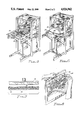
FIG. 4 illustrates a mold used to form the decorative speaker cover;
FIG. 5 shows disbursement or "wetting out" of the mold surface by the yet unexpanded foam medium over the entire surface of the mold liner achieved by tilting of the mold container;
FIG. 6 illustrates placement of a mold container under a press;
FIG. 7 shows a foam casting medium expanding over a mold; and
FIG. 8 shows the process of removing a rubber mold from the inventive speaker cover.
DETAILED DESCRIPTION OF AN ILLUSTRATIVE EMBODIMENT
As shown in the exemplary drawings, the present invention includes a decorative speaker cover and a method of making the decorative speaker cover. In a preferred embodiment, the speaker cover is molded in relief to match the corresponding appearance of an existing ceiling or wall panel. In use, it may be dropped directly into a T-bar type of suspended ceiling system or otherwise affixed to ceiling support members. With reference to the figures generally the cover is made by first forming a mold liner 26 from a panel to be duplicated by pouring a molding compound, such as, for example, silicone rubber, over the panel within a suitable form. After curing and removing from the form, the liner 26 is then placed in the bottom of a press on a hard surface. A closed cell foam in liquid form, such as, for example, a polyurethane foam, is spread over the entire mold surface and allowed to expand vertically as it cures. A press, i.e., a large flat plate, is placed a predetermined distance above the surface of the mold liner 26 to restrict the vertical expansion of the foam in order to control its density. Some foam escapes laterally from between the press and mold liner. The foam is allowed to cure and speaker cover 10 in relief is removed from the mold. The thickness of the speaker cover is then reduced to less than 0.7 cm by either shaving or sanding in order to form a thin sheet of a predetermined thickness The resulting speaker cover matches the duplicated panel and may be glued onto the front surface of a speaker for concealing the speaker in a drop ceiling or panelled wall. Other methods well known in the art may be used to place the speaker system and cover in walls and ceilings which have ornate relief patterns.
By way of example, the speaker cover indicated generally by reference 10 in FIG. 1 is shown mounted on the diaphragm of a hemispherically radiating speaker system 12. The speaker cover 10 is formed in relief to match existing panels in the ceiling in which the speaker system is to be installed. The speaker system generally indicated as 12 in FIGS. 1, 2 and 3 may illustratively take the form of a BES-C70D loudspeaker system, manufactured by B.E.S. Commercial Sound Products Division under their designation C70D and suitable for installation in a drop ceiling having "T" bar construction.
In the preferred embodiment, the speaker cover 10 is mounted on the surface of a planar diaphragm 14 with an adhesive bond along the edges of the contacting surfaces. Because speaker cover 10 is in physical contact with diaphragm 14 it radiates the acoustic vibrations generated in the diaphragm. The low density of the speaker cover assures that the frequency response of this radiating cover is consistent with the frequencies generated in the diaphragm. The inventor has discovered that suitable densities for the speaker cover range from approximately 1.9 to 2.2 lbs. per cubic foot. For a 23"×23" panel the overall weight should desirably be approximately 11 ounces.
Referring to FIG. 2 there is shown the back view of the loudspeaker system as described previously. An aluminum frame 16 supports the planar speaker diaphragm 14 and two independent magnetic circuits 20 and 22. In the preferred embodiment, this loudspeaker system fits into a standard T-bar frame for suspended ceiling systems having dimensions approximately 23 inches in length, 23 inches in width and 3 inches in depth.
Referring now to FIG. 3 there is shown a side view of speaker system 12 having speaker cover 10 adhesively attached to the front surface of the planar diaphragm 14 of the loudspeaker system. The speaker cover, formed in relief to match an existing panel, is attached along the edges 15 of planar diaphragm 14 using an appropriate adhesive such as a latex glue. The adhesive selected should be of a type which does not corrode the material of either the cover 10 or the speaker diaphragm 14. Solvent glues can be used if the mating surfaces are protected by non-sensitive coverings such as a latex paint. When placed in a ceiling or wall the front surface of speaker cover 10 replicates the ornamental shape and design of existing panels.
A method for making a relief speaker cover which duplicates the appearance of a panel is now described in detail. First, a panel to be duplicated is used to form a mold. Silicone rubber or another suitable molding compound is poured over the panel and allowed to dry completely, i.e., to cure. This results in a mold liner having a mirror image of the ornamental design and shape of the panel surface.
Referring to FIG. 4, mold liner 26 is placed in molding container 24. A predetermined amount of closed cell low density pour foam material such as a system based on polymeric isocyanate is then poured onto the mold liner. As illustrated in FIG. 5, mold container 24 is pivotally mounted on a gimbal (not shown) so that the foam may be evenly spread over mold liner 26 by tilting the mold container about the gimbal. This method of spreading of the liquid foam has been found necessary for controlling the uniform density of the finished panel. If the foam is allowed to expand along the mold liner surface, friction at the foam/liner interface causes collapse of many of the cells. So long as the entire surface of mold liner 26 is wetted with foam that has undergone minimal expansion, expansion is limited to a vertical direction above the mold liner. Otherwise, with expansion occurring along the mold liner surface, the distribution of foam cells becomes uneven and a substantial number of cells break open forming a dense skin on the relief surface. With the expansion occurring normal to the relief surface, the finished speaker cover accurately replicates the indentations and contours of the mold liner and has a uniform density.
Referring next to FIG. 6, the mold container 24 is positioned underneath press 28 immediately after spreading of the liquid foam material. As the form expands, it presses up against the bottom surface of press 28 and flows over the edges of the mold container 24.
Referring to FIG. 7 there is shown foam 30 expanding normal to the surface of mold liner 26. The press 28 is placed a predetermined distance from the surface of the design mold liner 26. As foam 30 expands it eventually contacts the bottom surface of press 28 and flows over the sides of the molding container 24. By adjusting the height of press 28 the density and weight of foam 30 can be controlled. For instance, if press 28 is moved further away from mold liner 26 a given amount of liquid foam will result in a panel which is relatively thick and of low density mass per unit volume. Moving press 28 closer to the surface of design mold 26 restricts the escape of form, thus causing the density of foam 30 to increase and the thickness of the resulting panel to decrease. Once foam 30 cures, the resulting panel 32 and rubber mold 26 are removed from the press.
Referring to FIG. 8 there is shown the process of removing the rubber mold liner 26 from the formed panel 32. Panel 32 is then cut and shaped to the desired thickness and length and width. The thin panel is colored to match the wall or ceiling design and is then adhesively attached as described above by an appropriate adhesive to the front planar surface of the loudspeaker system. It is noted that while attachment of the cover to the surface of the loudspeaker system is often preferred, it is not essential to the invention. Furthermore, if the finished panel is a uniform color, such color may be mixed into the liquid foam material.
Thus there has been shown a decorative speaker cover and a method of making the same in which the speaker cover includes the exact ornamental shape and design of a ceiling or wall panel. It is understood that the design of the inventive speaker cover can replicate any ornamental pattern and may form an integral part of a pattern, design or image which is greater in size than the speaker cover dimensions. The inventive cover may also be painted, dyed or otherwise colored to blend with other panels.
The speaker cover hides the front surface of a loudspeaker system which is placed in a ceiling or wall. While minimizing the loss of acoustic energy transmitted through the cover the inventive foam speaker cover also serves as a medium for replicating designs, textures, relief patterns and other visual images thus simulating wall or ceiling panels fabricated out of metal, fiberboard and other building materials. Several particular forms of the invention have been illustrated and described, but it will also be apparent that various modifications can be made without departing from the spirit and scope of the invention.

Claims (8)

We claim:
1. A speaker cover for a loudspeaker system for installation in a ceiling or wall composed of panels having a predetermined visible, external appearance, said speaker cover comprising a thin sheet of closed cell foam having a concealed rear surface facing the loudspeaker system and a front visible surface which has the same visible appearance as the panels so that when the speaker cover is installed, said cover appears to be one of the panels of the ceiling or wall.
2. The speaker cover of claim 1 to be installed in a ceiling or wall having an ornamental relief pattern, wherein said front surface includes the same relief pattern as the ceiling or wall.
3. The speaker cover of claim 1 wherein said thin sheet of closed cell foam has a density between 1.9 and 2.2 lbs. per cubic foot and a thickness between the front surface and the rear surface of less than 0.7 cm.
4. The speaker cover of claim 1 wherein said sheet fits into a standard T-bar frame for suspended ceilings.
5. The speaker cover of claim 2 wherein the front surface is a relief pattern identical to an ornamental metal ceiling panel.
6. A speaker cover to be placed in front of a loudspeaker, which, when installed in a ceiling or wall having an ornamental relief pattern, comprises a thin sheet of closed cell foam having a concealed rear surface facing the loudspeaker and a visible front surface which forms part of the ornamental ceiling pattern so that the speaker cover does not appear distinct from the rest of the ceiling or wall.
7. The speaker cover of claim 6 to be installed in a ceiling or wall having an ornamental relief pattern, wherein said front surface forms an integral part of the ornamental relief pattern.
8. The speaker cover of claim 6 wherein said thin sheet of closed cell foam has a density between 1.9 and 2.2 lbs. per cubic foot and a thickness between the front surface and the rear surface being less than 0.7 cm.
US07/237,138 1986-10-10 1988-08-29 Decorative speaker cover Expired - Lifetime US4926962A (en)

Priority Applications (1)

Application Number Priority Date Filing Date Title
US07/237,138 US4926962A (en) 1986-10-10 1988-08-29 Decorative speaker cover

Applications Claiming Priority (2)

Application Number Priority Date Filing Date Title
US06/917,735 US4769188A (en) 1986-10-10 1986-10-10 Method of forming a decorative foamed resin speaker cover
US07/237,138 US4926962A (en) 1986-10-10 1988-08-29 Decorative speaker cover

Related Parent Applications (1)

Application Number Title Priority Date Filing Date
US06/917,735 Division US4769188A (en) 1986-10-10 1986-10-10 Method of forming a decorative foamed resin speaker cover

Publications (1)

Publication Number Publication Date
US4926962A true US4926962A (en) 1990-05-22

Family

ID=26930402

Family Applications (1)

Application Number Title Priority Date Filing Date
US07/237,138 Expired - Lifetime US4926962A (en) 1986-10-10 1988-08-29 Decorative speaker cover

Country Status (1)

Country Link
US (1) US4926962A (en)

Cited By (12)

* Cited by examiner, † Cited by third party
Publication number Priority date Publication date Assignee Title
WO1993012637A1 (en) * 1991-12-12 1993-06-24 Blakeslee Thomas R Changeable art loudspeaker
USD406143S (en) * 1998-04-29 1999-02-23 Montaldo Stuart F Front face of speaker disguise
WO1999035636A1 (en) * 1998-01-07 1999-07-15 Noise Cancellation Technologies, Inc. Decorative speaker cover
US6056083A (en) * 1997-02-24 2000-05-02 Daniell; Stephen S. Loudspeakers in architectural form
US6147594A (en) * 1998-03-11 2000-11-14 Noise Cancellation Technologies, Inc. Method and apparatus for conveying audiovisual information
US20040129492A1 (en) * 2002-10-28 2004-07-08 Alejandro Bertagni Planar diaphragm loudspeaker and related methods
WO2007018905A1 (en) * 2005-07-25 2007-02-15 Audiovox Corporation Speaker cover
US20090087001A1 (en) * 2007-09-27 2009-04-02 Peigen Jiang Decorative loudspeaker grille
ITMI20081693A1 (en) * 2008-09-24 2010-03-25 Stefano Regazzoni ACOUSTIC DIFFUSERS WITH ACCIDENT EQUIPPED WITH MOBILE OCCULATION PANELS
CN107205182A (en) * 2017-06-21 2017-09-26 海盐四通管件制造有限公司 A kind of concealed audio amplifier
US20190088238A1 (en) * 2017-09-20 2019-03-21 Mitek Corp., Inc. Printable diffuser
US20230239600A1 (en) * 2022-01-24 2023-07-27 Fredrick Lane Cantabery Modularized Loudspeaker System Exterior Aesthetic

Citations (5)

* Cited by examiner, † Cited by third party
Publication number Priority date Publication date Assignee Title
US1837755A (en) * 1929-06-22 1931-12-22 Westinghouse Electric & Mfg Co Translating device
US2115098A (en) * 1935-12-26 1938-04-26 Rola Company Loudspeaker mounting
US4032725A (en) * 1976-09-07 1977-06-28 Motorola, Inc. Speaker mounting
US4123621A (en) * 1977-12-05 1978-10-31 Walker Frank J Acoustical speaker device
US4275278A (en) * 1978-08-18 1981-06-23 Sony Corporation Diaphragm for a loudspeaker

Patent Citations (5)

* Cited by examiner, † Cited by third party
Publication number Priority date Publication date Assignee Title
US1837755A (en) * 1929-06-22 1931-12-22 Westinghouse Electric & Mfg Co Translating device
US2115098A (en) * 1935-12-26 1938-04-26 Rola Company Loudspeaker mounting
US4032725A (en) * 1976-09-07 1977-06-28 Motorola, Inc. Speaker mounting
US4123621A (en) * 1977-12-05 1978-10-31 Walker Frank J Acoustical speaker device
US4275278A (en) * 1978-08-18 1981-06-23 Sony Corporation Diaphragm for a loudspeaker

Cited By (20)

* Cited by examiner, † Cited by third party
Publication number Priority date Publication date Assignee Title
WO1993012637A1 (en) * 1991-12-12 1993-06-24 Blakeslee Thomas R Changeable art loudspeaker
US6056083A (en) * 1997-02-24 2000-05-02 Daniell; Stephen S. Loudspeakers in architectural form
WO1999035636A1 (en) * 1998-01-07 1999-07-15 Noise Cancellation Technologies, Inc. Decorative speaker cover
US6142254A (en) * 1998-01-07 2000-11-07 Noise Cancellation Technologies, Inc. Decorative speaker cover
EP1053541A1 (en) * 1998-01-07 2000-11-22 Noise Cancellation Technologies, Inc. Decorative speaker cover
EP1053541A4 (en) * 1998-01-07 2006-09-13 Nct Group Inc Decorative speaker cover
US6147594A (en) * 1998-03-11 2000-11-14 Noise Cancellation Technologies, Inc. Method and apparatus for conveying audiovisual information
USD406143S (en) * 1998-04-29 1999-02-23 Montaldo Stuart F Front face of speaker disguise
US20040129492A1 (en) * 2002-10-28 2004-07-08 Alejandro Bertagni Planar diaphragm loudspeaker and related methods
US6929091B2 (en) * 2002-10-28 2005-08-16 Sound Advance Systems, Inc. Planar diaphragm loudspeaker and related methods
WO2007018905A1 (en) * 2005-07-25 2007-02-15 Audiovox Corporation Speaker cover
US20070036369A1 (en) * 2005-07-25 2007-02-15 Audiovox Corporation Speaker cover
US7826633B2 (en) 2005-07-25 2010-11-02 Audiovox Corporation Speaker cover
US20090087001A1 (en) * 2007-09-27 2009-04-02 Peigen Jiang Decorative loudspeaker grille
US8064629B2 (en) * 2007-09-27 2011-11-22 Peigen Jiang Decorative loudspeaker grille
ITMI20081693A1 (en) * 2008-09-24 2010-03-25 Stefano Regazzoni ACOUSTIC DIFFUSERS WITH ACCIDENT EQUIPPED WITH MOBILE OCCULATION PANELS
CN107205182A (en) * 2017-06-21 2017-09-26 海盐四通管件制造有限公司 A kind of concealed audio amplifier
US20190088238A1 (en) * 2017-09-20 2019-03-21 Mitek Corp., Inc. Printable diffuser
US10446131B2 (en) * 2017-09-20 2019-10-15 Mitek Corp., Inc. Printable diffuser
US20230239600A1 (en) * 2022-01-24 2023-07-27 Fredrick Lane Cantabery Modularized Loudspeaker System Exterior Aesthetic

Similar Documents

Publication Publication Date Title
US4769188A (en) Method of forming a decorative foamed resin speaker cover
US4926962A (en) Decorative speaker cover
US6929091B2 (en) Planar diaphragm loudspeaker and related methods
US5783264A (en) Decorative windows with contoured plastic resin laminated to glass
US3832264A (en) Self-reinforced plastic articles with core envelopment
US3621934A (en) Acoustic wall coverings
US3761554A (en) Method of making plastic articles with a substantially enveloped core
US3844523A (en) Mold having a breathable release sheet across the top
US1928034A (en) Sound-absorbent material
ES2105276T3 (en) PROCEDURE FOR THE MANUFACTURE OF A CONFORMED LAMINATE AND RESULTING PRODUCT.
CA2073819A1 (en) Tackable tile and method of making the same
US3444956A (en) Foam surfaced acoustical body
US4264544A (en) Method of molding a rigid integral skin foamed resin product in a mold having a vented lid
US3285364A (en) Loudspeaker construction
US3890415A (en) Box beam fabrication process
US4325177A (en) Modular art wall systems
US3838001A (en) Assembly for press-forming sheet material
US2021359A (en) Preformed sound-absorbing unit and method of making the same
CA2175839A1 (en) Core with foamed skin covering
US3773879A (en) Method of making a contour mold
GB2159764A (en) Composite foam articles and method for fabricating such articles
JPS6365800A (en) Ceiling structure provided with speaker
US5916843A (en) Picture with integrated picture frame
US4639283A (en) Method for making a diaphragm for an electro-acoustic transducer
EP0383125B1 (en) Method for the preparation of reproductions of frescoes or the like and reproductions of fragments of frescoes obtained by this method

Legal Events

Date Code Title Description
FEPP Fee payment procedure

Free format text: PAYOR NUMBER ASSIGNED (ORIGINAL EVENT CODE: ASPN); ENTITY STATUS OF PATENT OWNER: SMALL ENTITY

FPAY Fee payment

Year of fee payment: 4

FEPP Fee payment procedure

Free format text: PAYOR NUMBER ASSIGNED (ORIGINAL EVENT CODE: ASPN); ENTITY STATUS OF PATENT OWNER: SMALL ENTITY

Free format text: PAYER NUMBER DE-ASSIGNED (ORIGINAL EVENT CODE: RMPN); ENTITY STATUS OF PATENT OWNER: SMALL ENTITY

REMI Maintenance fee reminder mailed
FPAY Fee payment

Year of fee payment: 8

SULP Surcharge for late payment
FEPP Fee payment procedure

Free format text: PAYOR NUMBER ASSIGNED (ORIGINAL EVENT CODE: ASPN); ENTITY STATUS OF PATENT OWNER: SMALL ENTITY

Free format text: PAYER NUMBER DE-ASSIGNED (ORIGINAL EVENT CODE: RMPN); ENTITY STATUS OF PATENT OWNER: SMALL ENTITY

REMI Maintenance fee reminder mailed
FPAY Fee payment

Year of fee payment: 12

SULP Surcharge for late payment

Year of fee payment: 11

STCF Information on status: patent grant

Free format text: PATENTED CASE

FP Lapsed due to failure to pay maintenance fee

Effective date: 20020522