US4921416A - Injection molding machine having a system for detecting a nozzle leak construction - Google Patents
Injection molding machine having a system for detecting a nozzle leak construction Download PDFInfo
- Publication number
- US4921416A US4921416A US07/389,330 US38933089A US4921416A US 4921416 A US4921416 A US 4921416A US 38933089 A US38933089 A US 38933089A US 4921416 A US4921416 A US 4921416A
- Authority
- US
- United States
- Prior art keywords
- nozzle
- injection molding
- sprue
- molding machine
- predetermined
- Prior art date
- Legal status (The legal status is an assumption and is not a legal conclusion. Google has not performed a legal analysis and makes no representation as to the accuracy of the status listed.)
- Expired - Fee Related
Links
- 238000001746 injection moulding Methods 0.000 title claims abstract description 23
- 238000010276 construction Methods 0.000 title description 4
- 230000003213 activating effect Effects 0.000 claims description 5
- 239000000463 material Substances 0.000 description 5
- 230000008901 benefit Effects 0.000 description 2
- 230000004048 modification Effects 0.000 description 2
- 238000012986 modification Methods 0.000 description 2
- 238000000465 moulding Methods 0.000 description 2
- 235000001674 Agaricus brunnescens Nutrition 0.000 description 1
- 230000004888 barrier function Effects 0.000 description 1
- 230000008878 coupling Effects 0.000 description 1
- 238000010168 coupling process Methods 0.000 description 1
- 238000005859 coupling reaction Methods 0.000 description 1
- 238000001514 detection method Methods 0.000 description 1
- 230000006872 improvement Effects 0.000 description 1
- 238000002347 injection Methods 0.000 description 1
- 239000007924 injection Substances 0.000 description 1
- 230000013011 mating Effects 0.000 description 1
- 230000008439 repair process Effects 0.000 description 1
- 230000000007 visual effect Effects 0.000 description 1
- 239000002699 waste material Substances 0.000 description 1
Images

Classifications
-
- G—PHYSICS
- G01—MEASURING; TESTING
- G01M—TESTING STATIC OR DYNAMIC BALANCE OF MACHINES OR STRUCTURES; TESTING OF STRUCTURES OR APPARATUS, NOT OTHERWISE PROVIDED FOR
- G01M3/00—Investigating fluid-tightness of structures
- G01M3/002—Investigating fluid-tightness of structures by using thermal means
-
- B—PERFORMING OPERATIONS; TRANSPORTING
- B29—WORKING OF PLASTICS; WORKING OF SUBSTANCES IN A PLASTIC STATE IN GENERAL
- B29C—SHAPING OR JOINING OF PLASTICS; SHAPING OF MATERIAL IN A PLASTIC STATE, NOT OTHERWISE PROVIDED FOR; AFTER-TREATMENT OF THE SHAPED PRODUCTS, e.g. REPAIRING
- B29C45/00—Injection moulding, i.e. forcing the required volume of moulding material through a nozzle into a closed mould; Apparatus therefor
- B29C45/17—Component parts, details or accessories; Auxiliary operations
- B29C45/84—Safety devices
-
- B—PERFORMING OPERATIONS; TRANSPORTING
- B29—WORKING OF PLASTICS; WORKING OF SUBSTANCES IN A PLASTIC STATE IN GENERAL
- B29C—SHAPING OR JOINING OF PLASTICS; SHAPING OF MATERIAL IN A PLASTIC STATE, NOT OTHERWISE PROVIDED FOR; AFTER-TREATMENT OF THE SHAPED PRODUCTS, e.g. REPAIRING
- B29C45/00—Injection moulding, i.e. forcing the required volume of moulding material through a nozzle into a closed mould; Apparatus therefor
- B29C45/17—Component parts, details or accessories; Auxiliary operations
- B29C2045/1784—Component parts, details or accessories not otherwise provided for; Auxiliary operations not otherwise provided for
- B29C2045/1795—Means for detecting resin leakage or drooling from the injection nozzle
Definitions
- This invention relates to injection molding machines and in particular to an improvement in injection molding machines of the type having a nozzle mounted to inject a pressurized molten plastic into a mold cavity through a sprue and associated runner system.
- injection molding machines employ a stationery platen mounted to one mold half with an opening into the platen at the sprue of the mold. The tip or outlet end portion of the nozzle is mounted against a sprue bushing such that the molten plastic will be injected into the sprue.
- the nozzle to sprue bushing interface in these machines is designed to be a sealed interface to prevent leakage of the molten plastic from between the nozzle and sprue bushing, it is a known reocurring problem that such leakage does take place with resultant problems including, among others, delivery of an inadequate supply of plastic into the mold, loss of proper pressure, material waste, damage to sensitive controls and parts of the machine due to for example the high temperatures of the leaking molten plastic material and consequential machine down time for repairs and high finished part scrap.
- Nozzle leaks although principally occuring at the interface of the nozzle tip and sprue bushing, are known to occur at other locations associated with the nozzle such as for example at the nozzle attachment point to the machine's barrel which delivers the molten plastic to the nozzle.
- the leaking molten plastic can flow over different courses or paths.
- the molten plastic mushrooms or billows out from between the nozzle tip and sprue bushing interface due to a poor seal into the air space surrounding the nozzle in the platen opening.
- Other leaks are of a slow glittering type which actually clings to and creeps down the length of the nozzle eventually encrusting the nozzle or reaching the sensitive areas associated with the machine's operations.
- means for sensing the instantaneous temperature at a predetermined location within the air space surrounding the nozzle in the opening in the stationary platen of an injection molding machine where the predetermined location has a known normal operating temperature range and the means for sensing the instantaneous temperature generates signals which are coupled to control means for activating an alarm when a predetermined temperature exceeding the normal operating temperature range and representing a leak condition is detected.
- the means for sensing the instantaneous temperature is a thermocouple disposed at the predetermined location in the air space.
- the predetermined temperature representing a leak condition is above the normal operating temperature range and according to another feature, the predetermined temperature representing a leak condition is below the normal operating temperature range.
- thermocouple to be disposed in the airspace below the horizontally disposed nozzle.
- a still further important feature of the invention provides for the predetermined location to be disposed in the air space surrounding the nozzle relative to the interface of the nozzle and the sprue bushing of the machine.
- FIG. 1 is a side view in outline form of a typical horizontal injection molding machine of the general type to which the present invention is applicable;
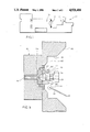
- FIG. 2 is an enlarged partial cross sectional view of the circled area A of the machine in FIG. 1 showing details of construction of a preferred embodiment of the invention.
- FIG. 3 is a further enlarged cross sectional view of the nozzle area in FIG. 2 showing further details of construction.
- FIG. 1 Shown in FIG. 1 is a horizontal type injection molding machine 10 to which the present invention is applicable.
- the detection system described hereinbelow is described in use with a horizontal type injection molding machine, so called vertical machines also exist and the invention is also applicable for use with such machines.
- the details of the construction and operation of the injection molding machine 10 are well known and need not be described in full detail for an understanding of the present invention.
- the injection molding machine 10 includes means shown generally as 12 in FIGS. 1 and 2 for delivering a pressurized molten plastic to a nozzle 14, shown in FIGS. 2 and 3, for injection into a mold cavity within a mold 16 through a sprue 18 and associated runner system, not shown in detail, in conventional and well known manner.
- the means for delivering the molten plastic includes, for example, a barrel 20 and associated heaters 22 and other controls for maintaining the molten state of the plastic and to which the nozzle 14 is mounted typically by way of an associated nozzle adapter 24.
- the nozzle 14 will carry further nozzle heaters such as 26, 28 and thermocouples.
- the nozzle outlet end 30 is sealedly seated against a mating nozzle seat 32 surrounding the sprue 18 in a sprue bushing 34 provided in one mold half 36, as shown in FIG. 3.
- the interface between the nozzle outlet end 30 and the seat 32 on the spure bushing preferrably is designed to provide for a leak free seal so that molten plastic will not escape, as shown as 35 in FIG. 3.
- the nozzle 14 passes through a tunnel opening 38 provided in a stationary platen 40 which is mounted to one side of the mold between the mold 16 and the machine barrel 20.
- the tunnel opening 38 in the platen can take different shapes but is typically coaxial with the sprue 18 and nozzle 14 and defines an annular clearance space or air space 42 around the nozzle.
- the normal operating temperature range of any location within the air space 42 can be determined and remains substantially within a known range for a given operating mode.
- the temperature characteristics at a predetermined location, for example location 44, within the air space 42 of the tunnel opening 38 relative to the nozzle and or to the nozzle to sprue bushing interface becomes known. Accordingly, when the temperature at the predetermined location 44 rises above the highest predetermined operating temperature for the particular setup, there is an indication that the hotter molten plastic has entered the air space due to a leak associated with the nozzle or its mounting. As will be described below, should the temperature at the predetermined location 44 fall below the lowest normal operating temperature for the particular mode of operation, there accordingly is an indication of a leak condition and further of a specific type of a leak.
- thermocouple 46 is mounted, for example, externally of the platen tunnel opening, such as to any convenient location on the machine housing or barrel, as shown in FIG. 2, and has it's heat sensitive tip positioned at the predetermined location 44.
- the thermocouple thereby senses and generates signals representing the instantaneous temperature at the predetermined location 44.
- An electronic controller 48 is coupled to the thermocouple 46 and receives the instantaneous temperature signals.
- the controller 48 is adapted to give either a visual or audible alarm when a temperature either above or below the normal operating temperature range is sensed, thus notifying the operator of a leak condition.
- the invention can respond to and differentiate between at least two different types of leaks.
- the operator would adjust the controller 48 to activate the alarm when temperatures at the predetermined location outside of a known predetermined normal operating temperature range are sensed depending on the particular mode of operation of the molding machine.
- the controller 48 would adjust the controller 48 to activate the alarm when temperatures at the predetermined location outside of a known predetermined normal operating temperature range are sensed depending on the particular mode of operation of the molding machine.
- the molten plastic escapes relatively slowly from between the nozzle to sprue bushing interface and clings to the nozzle and resolidifies on the nozzle which acts as a heat sink. In such case, the plastic material slowly works its way back along the nozzle until, if unchecked, it may reach the sensitive heaters and other controls associated with the nozzle and barrel of the machine.
- the controller activates the alarm, thereby alerting the operator to the leak condition before the plastic material reaches and damages the more sensitive parts of the machine as noted above. Further, because the leak condition was detected by a temperature below the normal operating temperature range, the operator is alerted to the possibility that the leak is of a slow, creeping or slithering type encrusting the nozzle.
Landscapes
- Engineering & Computer Science (AREA)
- Manufacturing & Machinery (AREA)
- Mechanical Engineering (AREA)
- Physics & Mathematics (AREA)
- General Physics & Mathematics (AREA)
- Injection Moulding Of Plastics Or The Like (AREA)
Abstract
An injection molding machine having a system for detecting nozzle leaks including a thermocouple positioned in the tunnel opening of a stationary platen of the machine at a predetermined location relative to the nozzle to sense instantaneous temperature at the location. A controller coupled to the thermocouple receives signals from the thermocouple and activates an alarm when the temperature in the tunnel opening falls outside of a predetermined normal operating temperature range.
Description
This invention relates to injection molding machines and in particular to an improvement in injection molding machines of the type having a nozzle mounted to inject a pressurized molten plastic into a mold cavity through a sprue and associated runner system. Typically, such injection molding machines employ a stationery platen mounted to one mold half with an opening into the platen at the sprue of the mold. The tip or outlet end portion of the nozzle is mounted against a sprue bushing such that the molten plastic will be injected into the sprue. Although the nozzle to sprue bushing interface in these machines is designed to be a sealed interface to prevent leakage of the molten plastic from between the nozzle and sprue bushing, it is a known reocurring problem that such leakage does take place with resultant problems including, among others, delivery of an inadequate supply of plastic into the mold, loss of proper pressure, material waste, damage to sensitive controls and parts of the machine due to for example the high temperatures of the leaking molten plastic material and consequential machine down time for repairs and high finished part scrap. Nozzle leaks, although principally occuring at the interface of the nozzle tip and sprue bushing, are known to occur at other locations associated with the nozzle such as for example at the nozzle attachment point to the machine's barrel which delivers the molten plastic to the nozzle. Depending on where the nozzle leak occurs and the rate of leakage, the leaking molten plastic can flow over different courses or paths. For example, in one type of leak, the molten plastic mushrooms or billows out from between the nozzle tip and sprue bushing interface due to a poor seal into the air space surrounding the nozzle in the platen opening. Other leaks are of a slow glittering type which actually clings to and creeps down the length of the nozzle eventually encrusting the nozzle or reaching the sensitive areas associated with the machine's operations.
It would therefore be highly desirable to provide for means to detect leaks associated with the nozzle of such machines so that corrective measures can be initiated before damage to expensive parts of the molding machine or excess scraped parts is encountered.
I have found that in general, regardless of the type of leak, that is in terms of rate of leakage or where the leak associated with the nozzle initiates and how it propagates, the temperature of the airspace in the platen tunnel opening surrounding the nozzle in injection molding machines of this type is effected and can be utilized as an indication of a leak condition associated with the nozzle.
In accordance with a preferred embodiment of the invention, means for sensing the instantaneous temperature at a predetermined location within the air space surrounding the nozzle in the opening in the stationary platen of an injection molding machine is provided, where the predetermined location has a known normal operating temperature range and the means for sensing the instantaneous temperature generates signals which are coupled to control means for activating an alarm when a predetermined temperature exceeding the normal operating temperature range and representing a leak condition is detected.
According to the invention, the means for sensing the instantaneous temperature is a thermocouple disposed at the predetermined location in the air space.
According to one feature of the invention, the predetermined temperature representing a leak condition is above the normal operating temperature range and according to another feature, the predetermined temperature representing a leak condition is below the normal operating temperature range.
A further important feature of the invention provides for the thermocouple to be disposed in the airspace below the horizontally disposed nozzle.
A still further important feature of the invention provides for the predetermined location to be disposed in the air space surrounding the nozzle relative to the interface of the nozzle and the sprue bushing of the machine.
The invention will be better understood after reading the following Detailed Description of the Preferred Embodiment in conjunction with the Drawing of which:
FIG. 1 is a side view in outline form of a typical horizontal injection molding machine of the general type to which the present invention is applicable;
FIG. 2 is an enlarged partial cross sectional view of the circled area A of the machine in FIG. 1 showing details of construction of a preferred embodiment of the invention; and
FIG. 3 is a further enlarged cross sectional view of the nozzle area in FIG. 2 showing further details of construction.
Shown in FIG. 1 is a horizontal type injection molding machine 10 to which the present invention is applicable. Although the detection system described hereinbelow is described in use with a horizontal type injection molding machine, so called vertical machines also exist and the invention is also applicable for use with such machines. The details of the construction and operation of the injection molding machine 10 are well known and need not be described in full detail for an understanding of the present invention. In general, the injection molding machine 10 includes means shown generally as 12 in FIGS. 1 and 2 for delivering a pressurized molten plastic to a nozzle 14, shown in FIGS. 2 and 3, for injection into a mold cavity within a mold 16 through a sprue 18 and associated runner system, not shown in detail, in conventional and well known manner. Typically, the means for delivering the molten plastic includes, for example, a barrel 20 and associated heaters 22 and other controls for maintaining the molten state of the plastic and to which the nozzle 14 is mounted typically by way of an associated nozzle adapter 24. Typically, the nozzle 14 will carry further nozzle heaters such as 26, 28 and thermocouples. The nozzle outlet end 30 is sealedly seated against a mating nozzle seat 32 surrounding the sprue 18 in a sprue bushing 34 provided in one mold half 36, as shown in FIG. 3. The interface between the nozzle outlet end 30 and the seat 32 on the spure bushing preferrably is designed to provide for a leak free seal so that molten plastic will not escape, as shown as 35 in FIG. 3. However, as noted hereinabove, for many varied reasons, it is known that over time leaks can develop at this interface allowing the molten plastic 35 to escape. In the typical injection molding machine, the nozzle 14 passes through a tunnel opening 38 provided in a stationary platen 40 which is mounted to one side of the mold between the mold 16 and the machine barrel 20. The tunnel opening 38 in the platen can take different shapes but is typically coaxial with the sprue 18 and nozzle 14 and defines an annular clearance space or air space 42 around the nozzle. In operation, the normal operating temperature range of any location within the air space 42 can be determined and remains substantially within a known range for a given operating mode. That is, when the machine is set up to melt, pressurize and deliver a given plastic material into a given mold, the temperature characteristics at a predetermined location, for example location 44, within the air space 42 of the tunnel opening 38 relative to the nozzle and or to the nozzle to sprue bushing interface becomes known. Accordingly, when the temperature at the predetermined location 44 rises above the highest predetermined operating temperature for the particular setup, there is an indication that the hotter molten plastic has entered the air space due to a leak associated with the nozzle or its mounting. As will be described below, should the temperature at the predetermined location 44 fall below the lowest normal operating temperature for the particular mode of operation, there accordingly is an indication of a leak condition and further of a specific type of a leak.
According to the invention, a thermocouple 46, preferrably of the type having a bendable shielded covering, is mounted, for example, externally of the platen tunnel opening, such as to any convenient location on the machine housing or barrel, as shown in FIG. 2, and has it's heat sensitive tip positioned at the predetermined location 44. The thermocouple thereby senses and generates signals representing the instantaneous temperature at the predetermined location 44. An electronic controller 48 is coupled to the thermocouple 46 and receives the instantaneous temperature signals. The controller 48 is adapted to give either a visual or audible alarm when a temperature either above or below the normal operating temperature range is sensed, thus notifying the operator of a leak condition. Those skilled in the art having the benefit of the objects and description of the invention can readily devise appropriate controls and alarm devices for coupling and responding to the thermocouple signals in the manner described and a complete detailed description of specific circuitry for doing so is not necessary here.
As noted above, different types of leaks occur in these machines and the invention can respond to and differentiate between at least two different types of leaks. In use, the operator would adjust the controller 48 to activate the alarm when temperatures at the predetermined location outside of a known predetermined normal operating temperature range are sensed depending on the particular mode of operation of the molding machine. Once in operation, should a mushrooming type leak occur at the nozzle to sprue bushing interface, as represented as 35 in FIG. 3, or at a mounting of the nozzle to the barrel, such as at the mounting adapter 24, high temperature molten plastic 35 will escape into the air space 42 causing a rise in the temperature in the air space at the location 44 which is sensed by the thermocouple 46 and controller 48 to sound the alarm. Should the leak be of the type that can be referred to as a "slithering" or "creeping" type leak, the molten plastic escapes relatively slowly from between the nozzle to sprue bushing interface and clings to the nozzle and resolidifies on the nozzle which acts as a heat sink. In such case, the plastic material slowly works its way back along the nozzle until, if unchecked, it may reach the sensitive heaters and other controls associated with the nozzle and barrel of the machine. As the molten plastic creeps back and resolidifies along the nozzle, it begins to form a crust on the nozzle which acts as a heat barrier between the heaters associated with the nozzle and barrel and the air space, whereby the temperature in the air space, for example at location 44, will actually decrease. This decrease in temperature is sensed by the thermocouple 46 and, when it falls below the known normal operating temperature range for the particular mode of operation, the controller activates the alarm, thereby alerting the operator to the leak condition before the plastic material reaches and damages the more sensitive parts of the machine as noted above. Further, because the leak condition was detected by a temperature below the normal operating temperature range, the operator is alerted to the possibility that the leak is of a slow, creeping or slithering type encrusting the nozzle.
Having described the preferred embodiment of the invention, those skilled in the art having the benefit of the description and accompanying drawings can readily devise other embodiments and modifications of the invention and such other embodiments and modifications are to be considered to be within the scope of the appended claims.
Claims (10)
1. An injection molding machine, comprising in combination:
a mold including a sprue;
a platen mounted to said mold, said platen including an opening generally coaxial with said sprue;
a nozzle mounted in said opening of said platen with an annular clearance space around at least a portion of the nozzle proximate an end thereof, said nozzle including an outlet disposed coaxial with said sprue from which a molten plastic is discharged into said sprue;
means for delivering a molten plastic to said nozzle;
means for detecting a leak condition including thermocouple means disposed in said clearance space at a predetermined location for generating signals representing an instantaneous temperature at said predetermined location, and
control means coupled to said thermocouple means for receiving said signals and for actuating an alarm when said signals correspond to a predetermined temperature corresponding to a leak condition.
2. The injection molding machine as defined in claim 1 wherein said control means activates said alarm means at a signal from said thermocouple means representing a temperature at said predetermined location in said clearance space above a predetermined normal operating temperature.
3. The injection molding machine as defined in claim 1 wherein said control means activates said alarm means at a signal from said thermocouple means representing a temperature at said predetermined location in said clearance space below a predetermined normal operating temperature.
4. The injection molding machine as defined in claim 1 wherein said predetermined location is proximate an interface between said nozzle and a sprue bushing of said mold.
5. The injection molding machine as defined in claim 4 wherein said nozzle is disposed in a horizontal orientation and said thermocouple predetermined locations is disposed below said nozzle in said clearance space.
6. An injection molding machine, comprising in combination:
a mold having at least one sprue bushing, said sprue bushing having a sprue;
at least one nozzle positioned against said sprue bushing said nozzle having an outlet coaxial with said sprue for injecting a molten plastic into said sprue;
a stationary platen mounted to said mold, said stationary platen including an opening, said nozzle disposed in said opening with an annular air space between said nozzle and said stationary platen, a predetermined location in said annular air space having a normal operating temperature range;
means for delivering said molten plastic to said nozzle;
means for detecting a leak condition including means disposed at said predetermined location in said air space relative to said nozzle for sensing an instantaneous temperature at said predetermined location, and
means responsive to said means for sensing the instantaneous temperature for activating an alarm at at least one predetermined sensed instantaneous temperature outside of said normal operating temperature range.
7. The injection molding machine as defined in claim 6 wherein said means for sensing the instantaneous temperature is a thermocouple.
8. The injection molding machine as defined in claim 7 wherein said means for activating the alarm is adapted to activate the alarm at a predetermined instantaneous temperature above said normal operating temperature range.
9. The injection molding machine as defined in claim 7 wherein said means for activating the alarm is adapted to activate the alarm at a predetermined instantaneous temperature below said normal operating temperature range.
10. An injection molding machine, comprising in combination;
a mold having a sprue;
a stationary platen mounted to said mold, said platen having a tunnel opening generally coaxial with said sprue;
a nozzle mounted in said tunnel opening with an annular air space in said tunnel opening between said nozzle and a wall of said tunnel opening;
means for delivering a molten plastic to said nozzle;
a thermocouple disposed at a predetermined location in said air space, and
means coupled to said thermocouple for activating an alarm at a predetermined temperature.
Priority Applications (1)
| Application Number | Priority Date | Filing Date | Title |
|---|---|---|---|
| US07/389,330 US4921416A (en) | 1989-08-03 | 1989-08-03 | Injection molding machine having a system for detecting a nozzle leak construction |
Applications Claiming Priority (1)
| Application Number | Priority Date | Filing Date | Title |
|---|---|---|---|
| US07/389,330 US4921416A (en) | 1989-08-03 | 1989-08-03 | Injection molding machine having a system for detecting a nozzle leak construction |
Publications (1)
| Publication Number | Publication Date |
|---|---|
| US4921416A true US4921416A (en) | 1990-05-01 |
Family
ID=23537807
Family Applications (1)
| Application Number | Title | Priority Date | Filing Date |
|---|---|---|---|
| US07/389,330 Expired - Fee Related US4921416A (en) | 1989-08-03 | 1989-08-03 | Injection molding machine having a system for detecting a nozzle leak construction |
Country Status (1)
| Country | Link |
|---|---|
| US (1) | US4921416A (en) |
Cited By (14)
| Publication number | Priority date | Publication date | Assignee | Title |
|---|---|---|---|---|
| WO1993018384A1 (en) * | 1992-03-06 | 1993-09-16 | Gerard Patrick Kennedy | A leak detector for an injection moulding machine |
| US5961898A (en) * | 1996-10-03 | 1999-10-05 | Matsushita Electric Industrial Co., Ltd. | Molding apparatus and molding method for light-permeable articles |
| FR2817500A1 (en) * | 2000-12-05 | 2002-06-07 | Michel Jacques Arias | SYSTEM FOR DETECTING THE FORMATION OF PLASTIC BLOCKS AT THE NOZZLE OF A PLASTIC INJECTION PRESS WHILE THE LATTER IS IN PRODUCTION WITH A MOLD |
| US20040076387A1 (en) * | 2002-10-17 | 2004-04-22 | Alcatel | Fiber optic tube and method of forming a fiber optic tube from a tape |
| US20050255189A1 (en) * | 2004-05-17 | 2005-11-17 | Manda Jan M | Method and apparatus for coupling melt conduits in a molding system and/or a runner system |
| US20080111264A1 (en) * | 2006-11-15 | 2008-05-15 | Husky Injection Molding Systems Ltd. | Vibration Based Injection Molding Machine Damage Detection and Health Monitoring |
| US20080131552A1 (en) * | 2006-11-30 | 2008-06-05 | Husky Injection Molding Systems Ltd. | Nozzle Sleeve for an Injection Molding Apparatus |
| US20080199554A1 (en) * | 2004-05-17 | 2008-08-21 | Husky Injection Molding Systems Ltd. | Method and apparatus for coupling melt conduits in a molding system and/or a runner system |
| US20080241299A1 (en) * | 2007-03-02 | 2008-10-02 | Maurizio Bazzo | Electronic Device for Controlling Plastics Injection Molds |
| DE102012109575A1 (en) | 2012-10-09 | 2014-04-10 | Wago Verwaltungsgesellschaft Mbh | Injection molding tool for injection molding machine, comprises gas suction pump and gas sensor, which stands in communicating connection with cavity and is connectable with monitoring unit that is arranged for detecting leakage |
| CN106426840A (en) * | 2016-09-26 | 2017-02-22 | 广东柳道热流道系统有限公司 | Hot runner glue leakage temperature control box detection system |
| WO2017083184A1 (en) * | 2015-11-11 | 2017-05-18 | Husky Injection Molding Systems Ltd. | Shooting pot refill control |
| DE202019101757U1 (en) * | 2019-03-27 | 2020-06-30 | Sulzer Mixpac Ag | Injection molding device |
| WO2021173551A1 (en) * | 2020-02-27 | 2021-09-02 | Incoe Corporation | Method and injection molding manifold adapted for leak detection during injection molding |
Citations (2)
| Publication number | Priority date | Publication date | Assignee | Title |
|---|---|---|---|---|
| US2551439A (en) * | 1949-02-07 | 1951-05-01 | George J Kovacs | Method and apparatus for molding thermoplastic materials |
| US3733059A (en) * | 1971-08-10 | 1973-05-15 | Rosemount Inc | Plastic extruder temperature control system |
-
1989
- 1989-08-03 US US07/389,330 patent/US4921416A/en not_active Expired - Fee Related
Patent Citations (2)
| Publication number | Priority date | Publication date | Assignee | Title |
|---|---|---|---|---|
| US2551439A (en) * | 1949-02-07 | 1951-05-01 | George J Kovacs | Method and apparatus for molding thermoplastic materials |
| US3733059A (en) * | 1971-08-10 | 1973-05-15 | Rosemount Inc | Plastic extruder temperature control system |
Cited By (28)
| Publication number | Priority date | Publication date | Assignee | Title |
|---|---|---|---|---|
| WO1993018384A1 (en) * | 1992-03-06 | 1993-09-16 | Gerard Patrick Kennedy | A leak detector for an injection moulding machine |
| GB2279461A (en) * | 1992-03-06 | 1995-01-04 | Teetotum Ltd | A leak detector for an injection moulding machine |
| US5542835A (en) * | 1992-03-06 | 1996-08-06 | Teetotum Limited | Leak detector for an injection moulding machine |
| US5961898A (en) * | 1996-10-03 | 1999-10-05 | Matsushita Electric Industrial Co., Ltd. | Molding apparatus and molding method for light-permeable articles |
| FR2817500A1 (en) * | 2000-12-05 | 2002-06-07 | Michel Jacques Arias | SYSTEM FOR DETECTING THE FORMATION OF PLASTIC BLOCKS AT THE NOZZLE OF A PLASTIC INJECTION PRESS WHILE THE LATTER IS IN PRODUCTION WITH A MOLD |
| WO2002045937A1 (en) * | 2000-12-05 | 2002-06-13 | Michel Arias | System for detecting formation of bottlenecks at a plastic injection press nozzle while the latter is operating with a mould |
| US20040076387A1 (en) * | 2002-10-17 | 2004-04-22 | Alcatel | Fiber optic tube and method of forming a fiber optic tube from a tape |
| US20070181282A1 (en) * | 2004-05-17 | 2007-08-09 | Husky Injection Molding Systems Ltd. | Heater for Compensating Heat Formerly Transmitted from Manifold to Plate of Hot Runner of Injection Molding System Usable for Molding Metal Alloy |
| US20070193713A1 (en) * | 2004-05-17 | 2007-08-23 | Husky Injection Molding Systems Ltd. | Transfer of Force from Manifold to Plate of Hot Runner of Injection Molding System Usable for Molding Metal Alloy |
| US20080199554A1 (en) * | 2004-05-17 | 2008-08-21 | Husky Injection Molding Systems Ltd. | Method and apparatus for coupling melt conduits in a molding system and/or a runner system |
| US20050255189A1 (en) * | 2004-05-17 | 2005-11-17 | Manda Jan M | Method and apparatus for coupling melt conduits in a molding system and/or a runner system |
| US20080111264A1 (en) * | 2006-11-15 | 2008-05-15 | Husky Injection Molding Systems Ltd. | Vibration Based Injection Molding Machine Damage Detection and Health Monitoring |
| US7481649B2 (en) | 2006-11-30 | 2009-01-27 | Husky Injection Molding Systems Ltd. | Injection molding apparatus having a nozzle sleeve |
| US20080131552A1 (en) * | 2006-11-30 | 2008-06-05 | Husky Injection Molding Systems Ltd. | Nozzle Sleeve for an Injection Molding Apparatus |
| US20080131553A1 (en) * | 2006-11-30 | 2008-06-05 | Husky Injection Molding Systems Ltd. | Injection Molding Apparatus having a Nozzle Sleeve |
| US7435078B2 (en) | 2006-11-30 | 2008-10-14 | Husky Injection Molding Systems Ltd. | Nozzle sleeve for an injection molding apparatus |
| US20080241299A1 (en) * | 2007-03-02 | 2008-10-02 | Maurizio Bazzo | Electronic Device for Controlling Plastics Injection Molds |
| DE102012109575A1 (en) | 2012-10-09 | 2014-04-10 | Wago Verwaltungsgesellschaft Mbh | Injection molding tool for injection molding machine, comprises gas suction pump and gas sensor, which stands in communicating connection with cavity and is connectable with monitoring unit that is arranged for detecting leakage |
| DE102012109575B4 (en) * | 2012-10-09 | 2015-12-17 | Wago Verwaltungsgesellschaft Mbh | Injection mold, leakage detection device for such an injection mold and method for detecting a leak in an injection mold |
| WO2017083184A1 (en) * | 2015-11-11 | 2017-05-18 | Husky Injection Molding Systems Ltd. | Shooting pot refill control |
| CN106426840A (en) * | 2016-09-26 | 2017-02-22 | 广东柳道热流道系统有限公司 | Hot runner glue leakage temperature control box detection system |
| DE202019101757U1 (en) * | 2019-03-27 | 2020-06-30 | Sulzer Mixpac Ag | Injection molding device |
| WO2021173551A1 (en) * | 2020-02-27 | 2021-09-02 | Incoe Corporation | Method and injection molding manifold adapted for leak detection during injection molding |
| US11396119B2 (en) * | 2020-02-27 | 2022-07-26 | Incoe Corporation | Method and injection molding manifold adapted for leak detection during injection molding |
| CN115151400A (en) * | 2020-02-27 | 2022-10-04 | 英科公司 | Method and injection molding manifold adapted for detecting leakage during injection molding |
| JP2023519481A (en) * | 2020-02-27 | 2023-05-11 | インコー コーポレーション | Adapted method and injection molding manifold for leak detection during injection molding |
| IL295209B1 (en) * | 2020-02-27 | 2024-01-01 | Incoe Corp | Injection molding method and manifold for detecting leaks during injection molding |
| IL295209B2 (en) * | 2020-02-27 | 2024-05-01 | Incoe Corp | Method and injection molding manifold adapted for leak detection during injection molding |
Similar Documents
| Publication | Publication Date | Title |
|---|---|---|
| US4921416A (en) | Injection molding machine having a system for detecting a nozzle leak construction | |
| EP0629287B1 (en) | Plastics injection moulding machine with a leak detector and a system therefor | |
| CN101219571B (en) | Method for a hot runner injection molding system | |
| US6544024B1 (en) | Apparatus for momentarily heating the surface of a mold | |
| US6048476A (en) | Clamp pressure optimization system and method | |
| WO2018108789A1 (en) | Stopper equipped with an integrated slag detection device | |
| JP2019181921A (en) | Injection molding device and injection molding method | |
| JPS623916A (en) | Method and apparatus for detecting quantity of leakage at injection molding machine | |
| CN215472919U (en) | Detection apparatus for fuse-element pressure and temperature suitable for injection moulding device | |
| KR20010063252A (en) | Apparatus for protecting the micro wave sounding device | |
| JP3903395B2 (en) | Method of controlling injection of filler material into protective tube of optical fiber and equipment for implementing the method | |
| JPS6325935B2 (en) | ||
| KR101845951B1 (en) | Resin spill alarm system of hot runner system | |
| US11396119B2 (en) | Method and injection molding manifold adapted for leak detection during injection molding | |
| KR890014191A (en) | Injection pressure management device of die cast machine and injection molding machine | |
| US4271106A (en) | Method for controlling an exothermic molding process | |
| JP2004330649A (en) | Controlling device of injection molding machine | |
| CN212707886U (en) | Hot runner glue leakage monitoring system | |
| KR100423744B1 (en) | Nozzle inside diameter cleanning and measuring apparatus of ladle | |
| JP4276451B2 (en) | Injection molding machine and temperature monitoring method thereof | |
| KR970002053Y1 (en) | Blocking device for pulverized coal distribution pipe | |
| US20040256753A1 (en) | Controlling injection moulding processes | |
| KR200307662Y1 (en) | An apparatus for checking a pressure in a blast furnace | |
| KR20030052414A (en) | A system for drilling a blocked pressure detection hole by using an air motor | |
| JPH085464A (en) | Optical fiber temperature measuring device for high temperature liquids |
Legal Events
| Date | Code | Title | Description |
|---|---|---|---|
| FPAY | Fee payment |
Year of fee payment: 4 |
|
| SULP | Surcharge for late payment | ||
| REMI | Maintenance fee reminder mailed | ||
| LAPS | Lapse for failure to pay maintenance fees | ||
| FP | Expired due to failure to pay maintenance fee |
Effective date: 19980506 |
|
| STCH | Information on status: patent discontinuation |
Free format text: PATENT EXPIRED DUE TO NONPAYMENT OF MAINTENANCE FEES UNDER 37 CFR 1.362 |