US491663A - Windmill - Google Patents
Windmill Download PDFInfo
- Publication number
- US491663A US491663A US491663DA US491663A US 491663 A US491663 A US 491663A US 491663D A US491663D A US 491663DA US 491663 A US491663 A US 491663A
- Authority
- US
- United States
- Prior art keywords
- vane
- bar
- wind
- frame
- levers
- Prior art date
- Legal status (The legal status is an assumption and is not a legal conclusion. Google has not performed a legal analysis and makes no representation as to the accuracy of the status listed.)
- Expired - Lifetime
Links
- 230000000153 supplemental effect Effects 0.000 description 6
- 241001541997 Allionia Species 0.000 description 2
- 238000010276 construction Methods 0.000 description 2
- 210000000707 wrist Anatomy 0.000 description 2
- 230000008878 coupling Effects 0.000 description 1
- 238000010168 coupling process Methods 0.000 description 1
- 238000005859 coupling reaction Methods 0.000 description 1
- 230000000630 rising effect Effects 0.000 description 1
Images
Classifications
-
- F—MECHANICAL ENGINEERING; LIGHTING; HEATING; WEAPONS; BLASTING
- F03—MACHINES OR ENGINES FOR LIQUIDS; WIND, SPRING, OR WEIGHT MOTORS; PRODUCING MECHANICAL POWER OR A REACTIVE PROPULSIVE THRUST, NOT OTHERWISE PROVIDED FOR
- F03D—WIND MOTORS
- F03D7/00—Controlling wind motors
- F03D7/02—Controlling wind motors the wind motors having rotation axis substantially parallel to the air flow entering the rotor
- F03D7/0204—Controlling wind motors the wind motors having rotation axis substantially parallel to the air flow entering the rotor for orientation in relation to wind direction
- F03D7/0208—Orientating out of wind
- F03D7/0212—Orientating out of wind the rotating axis remaining horizontal
-
- Y—GENERAL TAGGING OF NEW TECHNOLOGICAL DEVELOPMENTS; GENERAL TAGGING OF CROSS-SECTIONAL TECHNOLOGIES SPANNING OVER SEVERAL SECTIONS OF THE IPC; TECHNICAL SUBJECTS COVERED BY FORMER USPC CROSS-REFERENCE ART COLLECTIONS [XRACs] AND DIGESTS
- Y02—TECHNOLOGIES OR APPLICATIONS FOR MITIGATION OR ADAPTATION AGAINST CLIMATE CHANGE
- Y02E—REDUCTION OF GREENHOUSE GAS [GHG] EMISSIONS, RELATED TO ENERGY GENERATION, TRANSMISSION OR DISTRIBUTION
- Y02E10/00—Energy generation through renewable energy sources
- Y02E10/70—Wind energy
- Y02E10/72—Wind turbines with rotation axis in wind direction
Definitions
- the invention relates to improvements in wind mills.
- the object of the present invention is to simplify and improve the construction of wind mills, to equalize the strain and to enable them to be readily controlled.
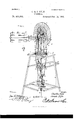
- Figure 1 is a perspective view of a wind mill constructedin accordance with this invention.
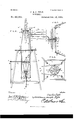
- Fig. 2 is a vertical sectional view.
- Fig. 3 is a horizontal sectional view on line m of Fig. 2.
- Fig. et is a similar view on line y, y.
- the rotating frame 2 is composed of four corner rods 5 bent outward intermediate of their ends at 6 and connected by a rectangular frame formed by horizontal bars or rods 7 which have their ends secured to the corner rods by couplings 8, and which carry intermediate their ends anti-friction rollers 9 which are arranged to bear against the walls of a circular opening 10 of the top 11 of the tower, whereby the frame 2 is enabled to rotate freely.
- the lower ends of the corner rods are connected by a circular plate 12 and is provided with a depending journal 13 which is arranged in a conical bearing 14 of a tube 15, and which is approximately conical to conform to the bearing and to enable the bearing of the frame 2 to be without friction.
- the journal 13 is provided with an annular groove 16 which is engaged by horizontal screws 17 of a sleeve 18 secured to the upper end of the tube 15 and preventing the journal rising from the conical bearing of the tube 15.
- the upper end of the bulged corner rods are connected by horizontal top pieces 19, and two of the corner rods support a horizontal vane bar 2O to the outer ends of which are attached vanes 21 and 22 composed of blades secured to bars 23 and 24, the former of which has its inner end pivoted in a bifurcation of the vane bar, thereby hinging the vane.
- the blade of the vane 21 is rigidly secured to the vane rod 23; and the blade of the vane 22 is provided with bearings 25 in which the vane rod 21 is journaled, whereby the vane 22 may turn on the rod to allow the wheel to swing out of the wind, or partially so.
- the vane 22 is held in a vertical position by a weight 26, and when the wind increases in force the vane is turned by it against the action of the weight.
- the vane 21 is the main vane, and is hinged, and is adapted to be arranged at an angle of forty-five degrees to the wheel to hold the latter into the wind, and to be turned parallel or in align with the wind wheel, to throw the latter out of the wind.
- the vane 22 is a supplemental one, and extends from the Vane bar at an angle to the wheel.
- the vanes are controlled by horizontal levers 27, which are fulcruined at one side of the frame and have their ends at the opposite side of the frame connected by a cross-bar 2S to which is attached a rope 29 or the like, which extends from the parallel levers 27 to the base of the tower.
- the parallel levers 27 are provided intermediate their ends with rollers 30 which are arranged on the inner faces of the levers, and which bear upon the upper face of a ring 31 to depress the ring and to allow the ring which is carried by the ver tical frame 2J to rotate without friction.
- the ring is provided with diametrically arranged bars 32 to which are attached wires 33,Which are connected with a wire 34 extending to an arm 36 of a bell-crank lever 37.
- the bell crank lever is T-shaped, and has the said IOC arm 36, which is arranged at right angles to the arms 38 and 39, and extends horizontally and adapted to be drawn down by the wire 33.
- the vertical arms 38 and 39 are connected by rods 40 and 41 with levers 42 and 43 which are fulcrumed intermediate their ends on the vane bar.
- the levers 42 and 43 are slightly curved at one end; the lever 42 has its curved end arranged below the vane bar and adapted to engage the vane 22 below the vane bar 24 to lturn the vane to a horizontal position and lift the weight; and the lever 43 has its curved end arranged above the vane bar and connected bya rod 44 with a vane 2l, and adapted to turn the vane to hold the wind wheel into the wind, and to throw the same out of the wind.
- the upper connecting bar 4l extends from the arm 38 of the T-shaped leverto the upper end of the lever 42, and the lower connecting rod 4l extends from the arm 39 to an intermediate point of the lever 42.
- the lower connecting rod 40 connects the lower end ot' thelever 43 with the arm 39, and the upper connecting rod extends from an intermediate point of the lever 43 to the arm 38.
- the shaft 3 carries disks 45, which are arranged at the ends of the shaft and are provided with wrist pins; and motion from the shaft is communicated to a pump rod 46 by a pair of pitmen rods 47, which have their upper ends connected to the wrist pins of the disks 45, and their lower ends attached tov outwardly extending arms 4SY of a ring 49 arranged on the tube.
- the upper ends of the corner rod of the rotating frame are connected by the top pieces and for-m two sidesbetween which the wind wheel rotates, and that the wind wheel is supported at both sides, thereby equalizing the strain and greatly facilitating the operation of the wind mill.
- a wind mill In a wind mill, the combination of a tower, a vertical frame rotatively mounted therein, a wind wheel mounted on the frame, a vane bar secured to the frame and arranged parallel with the wind wheel, a horizontally swinging main vane hinged at one end of the vane bar, a supplemental vane journaled at the other end of said bar, and means for controlling the vanes,substantially as described.
- a wind mill the combination of a tower, a vertical frame rotatively mounted therein, a wind wheel centrally arranged at the top of the frame, a vane bar secured to the vertical frame and arranged parallel with the wheel, a main vane hinged at one end of the vane bar, a supplemental vane journaled at the other end of the vane bar and provided with a depending weight, the curved levers fulcrumed on the vane bar and extending above and below the same, one of the levers being arrranged to engage the supplemental vane and the other lever being connected with the main vane, a T-shaped lever fulcrumed on the vane-bar and connected by rods with the curved lever, and means for connecting the T-shaped lever with the base of the tower, substantially as described.
- the combination ot' a tower. a vertical frame rotatively mounted therein, a wind wheel arranged at the upper end of the frame, a Vane bar secured to the frame and Varranged longitudinally of the wind wheel, a main vane hinged to one end of the vane bar, a supplemental vane journaled at the other end of the vane bar, levers fnlcrumed on the vane bar andadapted to turn the Vanes, a ring arranged on the lower p0rtion ot the vertical frame and connected with said levers, and parallel levers each having one end fulcrumed on the towerand provided intermediate its ends with an anti-friction roller arranged on the ring and having its other end connected with a base of the tower, substantially as described.
- a wind mill the combination of a tower, a vertical frame tapering from its middle to its end and rotatively mounted in the tower and carrying a wind wheel, a tube pro- Vided with a conical bearing at its upper end and having a securing llange at its lower end, a conical journal depending from the bottom of the vertical frame, and fitting in the conical bearing and providedwith an annular groove, and a sleeve secured to the upper end of the tube and receiving the journal and provided with screws arranged in said annular groove, substantially as and for the purpose described.
Landscapes
- Engineering & Computer Science (AREA)
- Life Sciences & Earth Sciences (AREA)
- Sustainable Development (AREA)
- Sustainable Energy (AREA)
- Chemical & Material Sciences (AREA)
- Combustion & Propulsion (AREA)
- Mechanical Engineering (AREA)
- General Engineering & Computer Science (AREA)
- Wind Motors (AREA)
Description
(No Model.) 2 Sheets-Sheet 1.
o. an J. PYLE.
WINDMILL.
No. 491,663. Y YPatented' Feb. 14, 1893.
/ Y l 'fg TH: Nonms crans no.4 mow-umu. wAsHmwoN, u. c`
(No Model.)
2 Sheets-Sheet 2.
C. 8v J. PYLE.
WINDMILL. No. 491,668. Patented Feb. 1.4, 1893.
M l k3 45 L v a F'l (5-2 4 .ff 4
J5 13 we ,2.3 23
20 0 J ,37) a lr6 Y l A `"7 E A7 F A l as .as Fl 6 4- y 30 :L
a l?? 3L Ilz 53 31 Z7 fl; 3L fl 3 az 28 6 5 ,4,7 *39 f a f8 e im,
j" ,17 2 A7 32 12 J5# "v3 5 l v Je a2 i 15 u 4 30 m/ f 9L F Z7 48 5 8 Hdgsss Iljymil's Charles? le UNTTnn STnTns PATENT Ormea.
CHARLES PYLE AND JOSEPH PYLE, OF- LEBANON, ASSIGNORS OF ONE- THIRD TO VILLIAM B. BRADSBY, OF GREENVILLE, ILLINOIS.
WlNDiVllLL...
SPECIF1CATION forming part of Letters Patent No. 491,663, dated February 14, 1893. Application led June 6, 1892. Serial No. 435,673. (No modali) To all whom t 11mg concern.-
Be it known that we, CHARLES PYLE and JOSEPH PYLE, citizens of the United States, residing at Lebanon, in the county of St. Clair and State of Illinois, have invented a new and useful Vindniill, of which the following is a specification.
The invention relates to improvements in wind mills.
The object of the present invention is to simplify and improve the construction of wind mills, to equalize the strain and to enable them to be readily controlled.
The invention consists in the construction and novel combination and arrangement of parts hereinafter fully described, illustrated in the accompanying drawings and pointed out in the claims hereto appended.
In the drawings-Figure 1 is a perspective view of a wind mill constructedin accordance with this invention. Fig. 2 is a vertical sectional view. Fig. 3 is a horizontal sectional view on line m of Fig. 2. Fig. et is a similar view on line y, y.
Like numerals of reference indicate correspondin g parts in all the figures of the drawings. y i
1 designates a tower in which is journaled a vertically disposed rotating frame 2 provided at its upper end with suitable bearings in which is journaled a shaft 3 carrying a centrally arranged wind wheel 4, which is supported at both sides thereby greatly equalizing the strain, and enabling the vertical frame 2 to rotate freely without friction. The rotating frame 2 is composed of four corner rods 5 bent outward intermediate of their ends at 6 and connected by a rectangular frame formed by horizontal bars or rods 7 which have their ends secured to the corner rods by couplings 8, and which carry intermediate their ends anti-friction rollers 9 which are arranged to bear against the walls of a circular opening 10 of the top 11 of the tower, whereby the frame 2 is enabled to rotate freely. The lower ends of the corner rods are connected by a circular plate 12 and is provided with a depending journal 13 which is arranged in a conical bearing 14 of a tube 15, and which is approximately conical to conform to the bearing and to enable the bearing of the frame 2 to be without friction. The journal 13 is provided with an annular groove 16 which is engaged by horizontal screws 17 of a sleeve 18 secured to the upper end of the tube 15 and preventing the journal rising from the conical bearing of the tube 15. The upper end of the bulged corner rods are connected by horizontal top pieces 19, and two of the corner rods support a horizontal vane bar 2O to the outer ends of which are attached vanes 21 and 22 composed of blades secured to bars 23 and 24, the former of which has its inner end pivoted in a bifurcation of the vane bar, thereby hinging the vane. The blade of the vane 21 is rigidly secured to the vane rod 23; and the blade of the vane 22 is provided with bearings 25 in which the vane rod 21 is journaled, whereby the vane 22 may turn on the rod to allow the wheel to swing out of the wind, or partially so. The vane 22 is held in a vertical position bya weight 26, and when the wind increases in force the vane is turned by it against the action of the weight. The vane 21 is the main vane, and is hinged, and is adapted to be arranged at an angle of forty-five degrees to the wheel to hold the latter into the wind, and to be turned parallel or in align with the wind wheel, to throw the latter out of the wind. The vane 22 is a supplemental one, and extends from the Vane bar at an angle to the wheel.
The vanes are controlled by horizontal levers 27, which are fulcruined at one side of the frame and have their ends at the opposite side of the frame connected by a cross-bar 2S to which is attached a rope 29 or the like, which extends from the parallel levers 27 to the base of the tower. The parallel levers 27 are provided intermediate their ends with rollers 30 which are arranged on the inner faces of the levers, and which bear upon the upper face of a ring 31 to depress the ring and to allow the ring which is carried by the ver tical frame 2J to rotate without friction. The ring is provided with diametrically arranged bars 32 to which are attached wires 33,Which are connected with a wire 34 extending to an arm 36 of a bell-crank lever 37. The bell crank lever is T-shaped, and has the said IOC arm 36, which is arranged at right angles to the arms 38 and 39, and extends horizontally and adapted to be drawn down by the wire 33. The vertical arms 38 and 39 are connected by rods 40 and 41 with levers 42 and 43 which are fulcrumed intermediate their ends on the vane bar. The levers 42 and 43 are slightly curved at one end; the lever 42 has its curved end arranged below the vane bar and adapted to engage the vane 22 below the vane bar 24 to lturn the vane to a horizontal position and lift the weight; and the lever 43 has its curved end arranged above the vane bar and connected bya rod 44 with a vane 2l, and adapted to turn the vane to hold the wind wheel into the wind, and to throw the same out of the wind. The upper connecting bar 4l extends from the arm 38 of the T-shaped leverto the upper end of the lever 42, and the lower connecting rod 4l extends from the arm 39 to an intermediate point of the lever 42. The lower connecting rod 40 connects the lower end ot' thelever 43 with the arm 39, and the upper connecting rod extends from an intermediate point of the lever 43 to the arm 38. By this arrangement the main vane, and the supplemental vane are simultaneouslyr operated by means of the parallel levers. The shaft 3 carries disks 45, which are arranged at the ends of the shaft and are provided with wrist pins; and motion from the shaft is communicated to a pump rod 46 by a pair of pitmen rods 47, which have their upper ends connected to the wrist pins of the disks 45, and their lower ends attached tov outwardly extending arms 4SY of a ring 49 arranged on the tube. l5, and connected with the pump rod by transverse pins 50 arranged in vertical slots of the tube 15, and disposed above and below the ring 49. The ring is connected by a rod 5l with the pump rod 46, and the tube is provided with an annular flange 52 which is secured to a horizontal board ot' the tower.
It will be seen that the upper ends of the corner rod of the rotating frame are connected by the top pieces and for-m two sidesbetween which the wind wheel rotates, and that the wind wheel is supported at both sides, thereby equalizing the strain and greatly facilitating the operation of the wind mill.
What we claim is l. In a wind mill, the combination of a tower, a vertical frame rotatively mounted therein, a wind wheel mounted on the frame, a vane bar secured to the frame and arranged parallel with the wind wheel, a horizontally swinging main vane hinged at one end of the vane bar, a supplemental vane journaled at the other end of said bar, and means for controlling the vanes,substantially as described.
2. In a wind mill, the combination of a tower, a vertical frame rotatively mounted therein, a wind wheel centrally arranged at the top of the frame, a vane bar secured to the vertical frame and arranged parallel with the wheel, a main vane hinged at one end of the vane bar, a supplemental vane journaled at the other end of the vane bar and provided with a depending weight, the curved levers fulcrumed on the vane bar and extending above and below the same, one of the levers being arrranged to engage the supplemental vane and the other lever being connected with the main vane, a T-shaped lever fulcrumed on the vane-bar and connected by rods with the curved lever, and means for connecting the T-shaped lever with the base of the tower, substantially as described.
3. In a wind mill, the combination ot' a tower. a vertical frame rotatively mounted therein, a wind wheel arranged at the upper end of the frame, a Vane bar secured to the frame and Varranged longitudinally of the wind wheel, a main vane hinged to one end of the vane bar, a supplemental vane journaled at the other end of the vane bar, levers fnlcrumed on the vane bar andadapted to turn the Vanes, a ring arranged on the lower p0rtion ot the vertical frame and connected with said levers, and parallel levers each having one end fulcrumed on the towerand provided intermediate its ends with an anti-friction roller arranged on the ring and having its other end connected with a base of the tower, substantially as described.
4. In a wind mill, the combination of a tower, a vertical frame tapering from its middle to its end and rotatively mounted in the tower and carrying a wind wheel, a tube pro- Vided with a conical bearing at its upper end and having a securing llange at its lower end, a conical journal depending from the bottom of the vertical frame, and fitting in the conical bearing and providedwith an annular groove, and a sleeve secured to the upper end of the tube and receiving the journal and provided with screws arranged in said annular groove, substantially as and for the purpose described.
In testimony that we claim the foregoing as our own we have hereto affixed our signatures in the presence of two witnesses.
CHARLES PYLE. JOSEPH PYLE. Witnesses:
LoUrs ZERWECK, JAMES T. ROGERS.
Publications (1)
| Publication Number | Publication Date |
|---|---|
| US491663A true US491663A (en) | 1893-02-14 |
Family
ID=2560509
Family Applications (1)
| Application Number | Title | Priority Date | Filing Date |
|---|---|---|---|
| US491663D Expired - Lifetime US491663A (en) | Windmill |
Country Status (1)
| Country | Link |
|---|---|
| US (1) | US491663A (en) |
-
0
- US US491663D patent/US491663A/en not_active Expired - Lifetime
Similar Documents
| Publication | Publication Date | Title |
|---|---|---|
| US232558A (en) | Hilliaed b | |
| US491663A (en) | Windmill | |
| US964374A (en) | Windmill. | |
| US94641A (en) | Improvement in wind-wheels | |
| US440266A (en) | Windmill | |
| US469786A (en) | Wind-wheel | |
| US146753A (en) | Improvement in windmills | |
| US31121A (en) | Windmill | |
| US538594A (en) | Windmill | |
| US711928A (en) | Windmill. | |
| US266524A (en) | Windmill | |
| US227540A (en) | Windmill | |
| US343786A (en) | Windmill | |
| US399645A (en) | Windmill | |
| US426241A (en) | Wind-wheel | |
| US258188A (en) | Windmill | |
| US162062A (en) | Improvement in windmills | |
| US593170A (en) | Monroe white | |
| US638603A (en) | Windmill. | |
| US838837A (en) | Windmill. | |
| US228677A (en) | John j | |
| US321292A (en) | Assigstob of one-foueth | |
| US162636A (en) | Improvement in windmills | |
| US137729A (en) | Improvement in windmills | |
| US189302A (en) | Improvement in windmills |