US4915473A - Pressure sensor utilizing a polyurethane optical fiber - Google Patents
Pressure sensor utilizing a polyurethane optical fiber Download PDFInfo
- Publication number
- US4915473A US4915473A US07/314,685 US31468589A US4915473A US 4915473 A US4915473 A US 4915473A US 31468589 A US31468589 A US 31468589A US 4915473 A US4915473 A US 4915473A
- Authority
- US
- United States
- Prior art keywords
- optical fiber
- pressure sensing
- sensing device
- light
- core
- Prior art date
- Legal status (The legal status is an assumption and is not a legal conclusion. Google has not performed a legal analysis and makes no representation as to the accuracy of the status listed.)
- Expired - Fee Related
Links
- 239000013307 optical fiber Substances 0.000 title claims abstract description 77
- 229920002635 polyurethane Polymers 0.000 title claims abstract description 30
- 239000004814 polyurethane Substances 0.000 title claims abstract description 30
- 125000001931 aliphatic group Chemical group 0.000 claims abstract description 15
- 229920001169 thermoplastic Polymers 0.000 claims abstract description 12
- 239000004416 thermosoftening plastic Substances 0.000 claims abstract description 12
- 239000000835 fiber Substances 0.000 claims description 25
- 239000000463 material Substances 0.000 claims description 14
- -1 polysiloxane Polymers 0.000 claims description 11
- LYCAIKOWRPUZTN-UHFFFAOYSA-N Ethylene glycol Chemical compound OCCO LYCAIKOWRPUZTN-UHFFFAOYSA-N 0.000 claims description 10
- 239000004970 Chain extender Substances 0.000 claims description 9
- 125000005442 diisocyanate group Chemical group 0.000 claims description 8
- 230000006835 compression Effects 0.000 claims description 7
- 238000007906 compression Methods 0.000 claims description 7
- 229920000642 polymer Polymers 0.000 claims description 7
- 229920001296 polysiloxane Polymers 0.000 claims description 7
- WGCNASOHLSPBMP-UHFFFAOYSA-N hydroxyacetaldehyde Natural products OCC=O WGCNASOHLSPBMP-UHFFFAOYSA-N 0.000 claims description 5
- KXDHJXZQYSOELW-UHFFFAOYSA-N Carbamic acid Chemical group NC(O)=O KXDHJXZQYSOELW-UHFFFAOYSA-N 0.000 claims description 4
- 125000003118 aryl group Chemical group 0.000 claims description 4
- 229910052739 hydrogen Inorganic materials 0.000 claims description 4
- 239000001257 hydrogen Substances 0.000 claims description 4
- 125000004435 hydrogen atom Chemical group [H]* 0.000 claims description 4
- IQPQWNKOIGAROB-UHFFFAOYSA-N isocyanate group Chemical group [N-]=C=O IQPQWNKOIGAROB-UHFFFAOYSA-N 0.000 claims description 4
- 125000001495 ethyl group Chemical group [H]C([H])([H])C([H])([H])* 0.000 claims description 2
- 125000002496 methyl group Chemical group [H]C([H])([H])* 0.000 claims description 2
- 239000011162 core material Substances 0.000 abstract description 29
- 239000013308 plastic optical fiber Substances 0.000 abstract description 7
- 238000001125 extrusion Methods 0.000 description 9
- 238000000034 method Methods 0.000 description 8
- 150000002009 diols Chemical class 0.000 description 5
- 239000011248 coating agent Substances 0.000 description 4
- 238000000576 coating method Methods 0.000 description 4
- 239000011521 glass Substances 0.000 description 4
- XUIMIQQOPSSXEZ-UHFFFAOYSA-N Silicon Chemical compound [Si] XUIMIQQOPSSXEZ-UHFFFAOYSA-N 0.000 description 3
- 229910052710 silicon Inorganic materials 0.000 description 3
- 239000010703 silicon Substances 0.000 description 3
- IAYPIBMASNFSPL-UHFFFAOYSA-N Ethylene oxide Chemical compound C1CO1 IAYPIBMASNFSPL-UHFFFAOYSA-N 0.000 description 2
- OAKJQQAXSVQMHS-UHFFFAOYSA-N Hydrazine Chemical compound NN OAKJQQAXSVQMHS-UHFFFAOYSA-N 0.000 description 2
- QIGBRXMKCJKVMJ-UHFFFAOYSA-N Hydroquinone Chemical compound OC1=CC=C(O)C=C1 QIGBRXMKCJKVMJ-UHFFFAOYSA-N 0.000 description 2
- AVXURJPOCDRRFD-UHFFFAOYSA-N Hydroxylamine Chemical class ON AVXURJPOCDRRFD-UHFFFAOYSA-N 0.000 description 2
- OKKJLVBELUTLKV-UHFFFAOYSA-N Methanol Chemical class OC OKKJLVBELUTLKV-UHFFFAOYSA-N 0.000 description 2
- GLUUGHFHXGJENI-UHFFFAOYSA-N Piperazine Chemical compound C1CNCCN1 GLUUGHFHXGJENI-UHFFFAOYSA-N 0.000 description 2
- 229920013701 VORANOL™ Polymers 0.000 description 2
- 125000002947 alkylene group Chemical group 0.000 description 2
- 150000004985 diamines Chemical class 0.000 description 2
- 150000002334 glycols Chemical class 0.000 description 2
- 239000000126 substance Substances 0.000 description 2
- CLDURKLVDJRELV-UHFFFAOYSA-N 1,2,3,3,4,4-hexafluoropentane-1,5-diol Chemical group OCC(F)(F)C(F)(F)C(F)C(O)F CLDURKLVDJRELV-UHFFFAOYSA-N 0.000 description 1
- ROHUXHMNZLHBSF-UHFFFAOYSA-N 1,4-bis(isocyanatomethyl)cyclohexane Chemical compound O=C=NCC1CCC(CN=C=O)CC1 ROHUXHMNZLHBSF-UHFFFAOYSA-N 0.000 description 1
- CDMDQYCEEKCBGR-UHFFFAOYSA-N 1,4-diisocyanatocyclohexane Chemical compound O=C=NC1CCC(N=C=O)CC1 CDMDQYCEEKCBGR-UHFFFAOYSA-N 0.000 description 1
- VLVVSHOQIJBJAG-UHFFFAOYSA-N 1,6-diisocyanato-2,2,4,4-tetramethylhexane Chemical compound O=C=NCCC(C)(C)CC(C)(C)CN=C=O VLVVSHOQIJBJAG-UHFFFAOYSA-N 0.000 description 1
- ATOUXIOKEJWULN-UHFFFAOYSA-N 1,6-diisocyanato-2,2,4-trimethylhexane Chemical compound O=C=NCCC(C)CC(C)(C)CN=C=O ATOUXIOKEJWULN-UHFFFAOYSA-N 0.000 description 1
- QGLRLXLDMZCFBP-UHFFFAOYSA-N 1,6-diisocyanato-2,4,4-trimethylhexane Chemical compound O=C=NCC(C)CC(C)(C)CCN=C=O QGLRLXLDMZCFBP-UHFFFAOYSA-N 0.000 description 1
- CWKVFRNCODQPDB-UHFFFAOYSA-N 1-(2-aminoethylamino)propan-2-ol Chemical compound CC(O)CNCCN CWKVFRNCODQPDB-UHFFFAOYSA-N 0.000 description 1
- LYDHLGJJJAWBDY-UHFFFAOYSA-N 1-isocyanato-4-[2-(4-isocyanatocyclohexyl)propan-2-yl]cyclohexane Chemical compound C1CC(N=C=O)CCC1C(C)(C)C1CCC(N=C=O)CC1 LYDHLGJJJAWBDY-UHFFFAOYSA-N 0.000 description 1
- OKWLUBCSBVYYTC-UHFFFAOYSA-N 1-phenylbutane-1,4-diol Chemical compound OCCCC(O)C1=CC=CC=C1 OKWLUBCSBVYYTC-UHFFFAOYSA-N 0.000 description 1
- UEBZASVZJYRARW-UHFFFAOYSA-N 2-isocyanato-1,3-dimethylidenecyclohexane Chemical compound C=C1CCCC(=C)C1N=C=O UEBZASVZJYRARW-UHFFFAOYSA-N 0.000 description 1
- JCJUSOXPQYDXMX-UHFFFAOYSA-N 2-isocyanato-1,4-dimethylidenecyclohexane Chemical compound C=C1CCC(=C)C(N=C=O)C1 JCJUSOXPQYDXMX-UHFFFAOYSA-N 0.000 description 1
- BPBDZXFJDMJLIB-UHFFFAOYSA-N 2-phenylpropane-1,3-diol Chemical compound OCC(CO)C1=CC=CC=C1 BPBDZXFJDMJLIB-UHFFFAOYSA-N 0.000 description 1
- 239000005058 Isophorone diisocyanate Substances 0.000 description 1
- GOOHAUXETOMSMM-UHFFFAOYSA-N Propylene oxide Chemical compound CC1CO1 GOOHAUXETOMSMM-UHFFFAOYSA-N 0.000 description 1
- WYURNTSHIVDZCO-UHFFFAOYSA-N Tetrahydrofuran Chemical compound C1CCOC1 WYURNTSHIVDZCO-UHFFFAOYSA-N 0.000 description 1
- ZJCCRDAZUWHFQH-UHFFFAOYSA-N Trimethylolpropane Chemical compound CCC(CO)(CO)CO ZJCCRDAZUWHFQH-UHFFFAOYSA-N 0.000 description 1
- 229920006397 acrylic thermoplastic Polymers 0.000 description 1
- 229910052782 aluminium Inorganic materials 0.000 description 1
- XAGFODPZIPBFFR-UHFFFAOYSA-N aluminium Chemical compound [Al] XAGFODPZIPBFFR-UHFFFAOYSA-N 0.000 description 1
- 125000004202 aminomethyl group Chemical group [H]N([H])C([H])([H])* 0.000 description 1
- 238000003491 array Methods 0.000 description 1
- DZYFUUQMKQBVBY-UHFFFAOYSA-N bis(2-isocyanatoethyl) carbonate Chemical compound O=C=NCCOC(=O)OCCN=C=O DZYFUUQMKQBVBY-UHFFFAOYSA-N 0.000 description 1
- 125000004432 carbon atom Chemical group C* 0.000 description 1
- 238000007796 conventional method Methods 0.000 description 1
- 238000002425 crystallisation Methods 0.000 description 1
- 230000008025 crystallization Effects 0.000 description 1
- 238000001723 curing Methods 0.000 description 1
- KQWGXHWJMSMDJJ-UHFFFAOYSA-N cyclohexyl isocyanate Chemical compound O=C=NC1CCCCC1 KQWGXHWJMSMDJJ-UHFFFAOYSA-N 0.000 description 1
- 230000001419 dependent effect Effects 0.000 description 1
- MTHSVFCYNBDYFN-UHFFFAOYSA-N diethylene glycol Chemical class OCCOCCO MTHSVFCYNBDYFN-UHFFFAOYSA-N 0.000 description 1
- KIQKWYUGPPFMBV-UHFFFAOYSA-N diisocyanatomethane Chemical class O=C=NCN=C=O KIQKWYUGPPFMBV-UHFFFAOYSA-N 0.000 description 1
- 238000007598 dipping method Methods 0.000 description 1
- 230000000694 effects Effects 0.000 description 1
- 238000005516 engineering process Methods 0.000 description 1
- 238000013007 heat curing Methods 0.000 description 1
- 238000010438 heat treatment Methods 0.000 description 1
- 150000002483 hydrogen compounds Chemical class 0.000 description 1
- 125000002887 hydroxy group Chemical group [H]O* 0.000 description 1
- NIMLQBUJDJZYEJ-UHFFFAOYSA-N isophorone diisocyanate Chemical compound CC1(C)CC(N=C=O)CC(C)(CN=C=O)C1 NIMLQBUJDJZYEJ-UHFFFAOYSA-N 0.000 description 1
- 239000000155 melt Substances 0.000 description 1
- 239000002184 metal Substances 0.000 description 1
- 229910052751 metal Inorganic materials 0.000 description 1
- AYLRODJJLADBOB-QMMMGPOBSA-N methyl (2s)-2,6-diisocyanatohexanoate Chemical compound COC(=O)[C@@H](N=C=O)CCCCN=C=O AYLRODJJLADBOB-QMMMGPOBSA-N 0.000 description 1
- 239000000203 mixture Substances 0.000 description 1
- 239000002245 particle Substances 0.000 description 1
- WXZMFSXDPGVJKK-UHFFFAOYSA-N pentaerythritol Chemical compound OCC(CO)(CO)CO WXZMFSXDPGVJKK-UHFFFAOYSA-N 0.000 description 1
- 125000001997 phenyl group Chemical group [H]C1=C([H])C([H])=C(*)C([H])=C1[H] 0.000 description 1
- 229920003023 plastic Polymers 0.000 description 1
- 239000004033 plastic Substances 0.000 description 1
- 229920003229 poly(methyl methacrylate) Polymers 0.000 description 1
- 125000002924 primary amino group Chemical group [H]N([H])* 0.000 description 1
- 230000005855 radiation Effects 0.000 description 1
- 230000000717 retained effect Effects 0.000 description 1
- 238000005507 spraying Methods 0.000 description 1
- ISXSCDLOGDJUNJ-UHFFFAOYSA-N tert-butyl prop-2-enoate Chemical compound CC(C)(C)OC(=O)C=C ISXSCDLOGDJUNJ-UHFFFAOYSA-N 0.000 description 1
- WFKWXMTUELFFGS-UHFFFAOYSA-N tungsten Chemical compound [W] WFKWXMTUELFFGS-UHFFFAOYSA-N 0.000 description 1
- 229910052721 tungsten Inorganic materials 0.000 description 1
- 239000010937 tungsten Substances 0.000 description 1
Images


Classifications
-
- G—PHYSICS
- G01—MEASURING; TESTING
- G01L—MEASURING FORCE, STRESS, TORQUE, WORK, MECHANICAL POWER, MECHANICAL EFFICIENCY, OR FLUID PRESSURE
- G01L1/00—Measuring force or stress, in general
- G01L1/24—Measuring force or stress, in general by measuring variations of optical properties of material when it is stressed, e.g. by photoelastic stress analysis using infrared, visible light, ultraviolet
- G01L1/242—Measuring force or stress, in general by measuring variations of optical properties of material when it is stressed, e.g. by photoelastic stress analysis using infrared, visible light, ultraviolet the material being an optical fibre
- G01L1/243—Measuring force or stress, in general by measuring variations of optical properties of material when it is stressed, e.g. by photoelastic stress analysis using infrared, visible light, ultraviolet the material being an optical fibre using means for applying force perpendicular to the fibre axis
-
- C—CHEMISTRY; METALLURGY
- C08—ORGANIC MACROMOLECULAR COMPOUNDS; THEIR PREPARATION OR CHEMICAL WORKING-UP; COMPOSITIONS BASED THEREON
- C08G—MACROMOLECULAR COMPOUNDS OBTAINED OTHERWISE THAN BY REACTIONS ONLY INVOLVING UNSATURATED CARBON-TO-CARBON BONDS
- C08G18/00—Polymeric products of isocyanates or isothiocyanates
- C08G18/06—Polymeric products of isocyanates or isothiocyanates with compounds having active hydrogen
- C08G18/28—Polymeric products of isocyanates or isothiocyanates with compounds having active hydrogen characterised by the compounds used containing active hydrogen
- C08G18/40—High-molecular-weight compounds
- C08G18/48—Polyethers
- C08G18/4825—Polyethers containing two hydroxy groups
-
- C—CHEMISTRY; METALLURGY
- C08—ORGANIC MACROMOLECULAR COMPOUNDS; THEIR PREPARATION OR CHEMICAL WORKING-UP; COMPOSITIONS BASED THEREON
- C08G—MACROMOLECULAR COMPOUNDS OBTAINED OTHERWISE THAN BY REACTIONS ONLY INVOLVING UNSATURATED CARBON-TO-CARBON BONDS
- C08G18/00—Polymeric products of isocyanates or isothiocyanates
- C08G18/06—Polymeric products of isocyanates or isothiocyanates with compounds having active hydrogen
- C08G18/28—Polymeric products of isocyanates or isothiocyanates with compounds having active hydrogen characterised by the compounds used containing active hydrogen
- C08G18/40—High-molecular-weight compounds
- C08G18/48—Polyethers
- C08G18/4833—Polyethers containing oxyethylene units
- C08G18/4837—Polyethers containing oxyethylene units and other oxyalkylene units
-
- G—PHYSICS
- G02—OPTICS
- G02B—OPTICAL ELEMENTS, SYSTEMS OR APPARATUS
- G02B1/00—Optical elements characterised by the material of which they are made; Optical coatings for optical elements
- G02B1/04—Optical elements characterised by the material of which they are made; Optical coatings for optical elements made of organic materials, e.g. plastics
- G02B1/045—Light guides
- G02B1/046—Light guides characterised by the core material
-
- Y—GENERAL TAGGING OF NEW TECHNOLOGICAL DEVELOPMENTS; GENERAL TAGGING OF CROSS-SECTIONAL TECHNOLOGIES SPANNING OVER SEVERAL SECTIONS OF THE IPC; TECHNICAL SUBJECTS COVERED BY FORMER USPC CROSS-REFERENCE ART COLLECTIONS [XRACs] AND DIGESTS
- Y10—TECHNICAL SUBJECTS COVERED BY FORMER USPC
- Y10T—TECHNICAL SUBJECTS COVERED BY FORMER US CLASSIFICATION
- Y10T428/00—Stock material or miscellaneous articles
- Y10T428/24—Structurally defined web or sheet [e.g., overall dimension, etc.]
- Y10T428/24479—Structurally defined web or sheet [e.g., overall dimension, etc.] including variation in thickness
- Y10T428/24496—Foamed or cellular component
- Y10T428/24504—Component comprises a polymer [e.g., rubber, etc.]
- Y10T428/24512—Polyurethane
-
- Y—GENERAL TAGGING OF NEW TECHNOLOGICAL DEVELOPMENTS; GENERAL TAGGING OF CROSS-SECTIONAL TECHNOLOGIES SPANNING OVER SEVERAL SECTIONS OF THE IPC; TECHNICAL SUBJECTS COVERED BY FORMER USPC CROSS-REFERENCE ART COLLECTIONS [XRACs] AND DIGESTS
- Y10—TECHNICAL SUBJECTS COVERED BY FORMER USPC
- Y10T—TECHNICAL SUBJECTS COVERED BY FORMER US CLASSIFICATION
- Y10T428/00—Stock material or miscellaneous articles
- Y10T428/31504—Composite [nonstructural laminate]
- Y10T428/31551—Of polyamidoester [polyurethane, polyisocyanate, polycarbamate, etc.]
Definitions
- This invention relates to a novel pressure sensing device.
- this invention relates to a pressure sensing device utilizing a polymer optical fiber with a core comprised of a flexible thermoplastic aliphatic segmented polyurethane.
- optical fiber based pressure sensors eliminates the problem of electromagnetic interference.
- present optical fibers are primarily fabricated from glass or hard glassy polymers such as acrylics and styrenics. Such optical fibers possess low flexibility and low strength. Such polymer optical fibers also sometimes possess low use temperatures. These limitations of the present optical fibers result in optical fiber based pressure sensors which are easily damaged.
- the invention is an optical fiber pressure sensing device comprising:
- a pressure sensing component comprising:
- (F) optionally an informational handling system capable of recording the light intensity signal received from the light detector.
- optical fibers useful in this invention are flexible.
- the inventive pressure sensing device utilizing such polymer optical fibers is therefore durable and immune to electromagnetic interference.
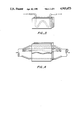
- FIGS. 1 and 2 illustrate schematic representations of the pressure sensor of this invention.
- FIG. 3 illustrates the deployment of a single fiber between the compressive means.
- FIG. 4 illustrates the deployment of multiple fibers between the compressive means.
- FIG. 5 illustrates the experimental pressure sensor layout of Example 1.
- FIGS. 6-11 illustrate data on power change, load, and diameter compression obtained with the pressure sensor of Example 1.
- the invention is an optical fiber based pressure sensor utilizing a polymer optical fiber comprising a core of a flexible thermoplastic aliphatic segmented polyurethane which is capable of transmitting light.
- S represents the light source.
- D represents the light detector and optional informational handling system.
- T 1 represents the means of transmitting light from the light source to the pressure sensing component PS which comprises the optical fiber(s) and the compressive means.
- T 2 represents the means of transmitting light from the pressure sensing component PS to the light detector and optional informational handling system D.
- single or multiple optical fibers may be deployed between the compressive means as illustrated by FIGS. 3 and 4.
- the light source may be any source capable of transmitting light through the optical fiber(s) over wavelengths of from about 400 to about 900 nanometers.
- the light source may be monochromatic or polychromatic.
- the light source may be a visible region tungsten bulb, a light emitting diode, a gaseous laser, or other light source. See Kist, "Sources and Detectors for Fiber-optic Systems," Optical Fiber Sensors, Martinus Nijhoff Publishers, 1987, pp. 267-298, incorporated herein by reference.
- the light from the light source may optionally be passed through a focussing means before being transmitted to the optical fiber(s).
- the means of transmitting light from the light source to the pressure sensing component preferably comprises an optical fiber possessing an attenuation of less than about 20 decibels/meter. Such an optical fiber may be fabricated from glass or polymers. More preferably, the means of transmitting light from the light source to the pressure sensing component comprises the flexible thermoplastic aliphatic segmented polyurethane core fiber utilized in the pressure sensing component.
- the optical fibers useful in the pressure sensing component possess cores fabricated from flexible thermoplastic aliphatic segmented polyurethanes.
- Polyurethanes preferred for use in this invention are formed by the reaction of a glycol, a diisocyanate, and a chain extender as described in Collins, U.S. Pat. No. 4,621,113, incorporated herein by reference.
- Such polyurethanes preferably comprise alternating soft and hard segments,
- n residues of one or more methylolterminated polyetherglycols having molecular weights of from about 1000 to about 6000 and consisting essentially of chains of --O--CRR 1 --CH 2 -- units in which each of R and R 1 is hydrogen, methyl, or ethyl independently, except that in at least a preponderance of said units one or the other of R and R 1 is not hydrogen, and
- said hard segments being derivable from the reaction of a chain extender with the isocyanate end groups in said molecules and with one or more non-aromatic non-polymeric diisocyanates of a nature such that the resulting carbamate groups will be unable to associate with each other in such a manner as to result in domain crystallinity in the resulting polymer.
- Preferred glycols used to form the polyurethanes useful in this invention are predominantly derivable from branched C 3-6 alkylene oxides, more preferably propylene oxide and/or butylene oxide. Some ethylene oxide derivable units may be included, so long as the essential effect of branched units on the character of the pre- and final polymers is retained and phase crystallization does not occur. The amount of ethylene oxide units to branched alkylene oxide units is preferably less than about 20 weight percent.
- Glycols especially preferred for use in this invention include poly(oxypropylene-oxyethylene)glycol, for example, VORANOL® 5287 diol (® trademark of The Dow Chemical Company), and poly(oxybutyleneoxyethylene)glycol.
- the diisocyanates useful in this invention comprise no aromatic moieties and comprise only aliphatic and/or cycloaliphatic moieties
- Preferred diisocyanates include polymethylene diisocyanates, 1,4-bis(isocyanatomethyl)cyclohexane, cyclohexane-1,4-diisocyanate, 2,2,4-trimethylhexamethylene diisocyanate, di(isocyanatoethyl)carbonate, lysine diisocyanate, isophorone diisocyanate, 1,8 diisocyanato-p-methane, 1,6-diisocyanato-2,2,4,4 tetramethylhexane, 1,6-diisocyanato-2,4,4 trimethylhexane, menthylene bis(4-cyclohexylisocyanate), isopropylidene bis(4-isocyanatocyclohexane), 1,4-dimethylene isocyan
- Preferred chain extenders include aliphatic C 2-4 straight chain and branched chain diols, diamines, and hydroxyamines; hydrazine and piperazine; cyclo- and dicycloaliphatic diols, diamines, or hydroxyamines having up to 12 carbon atoms, hydroquinone and resorcinol--as such or as the bis(2-hydroxyethyl)ethers, and aromatic and heterogenous nuclei--as such or hydrogenated, and substituted with two groups which are methylol and/or aminomethyl. More preferred chain extenders are aliphatic straight and branched chain C 2-4 diols.
- hydroxy and/or amino compounds considered suitable chain extenders include pentaerythritol, trimethylolpropane and N(-2-hydroxypropyl)ethylenediamine.
- Other suitable types of chain extenders include fluorine-substituted, difunctional active hydrogen compounds, for example, 1,2,3,3,4,4-hexafluoropentane-1,5 diol and phenyl substituted C 2-5 diols, preferably 2-phenyl-1,3-propylene glycol or phenyl-1,4-butylene glycol.
- the mole ratio of glycol:diisocyanate:chain extender is preferably in the range from about 1:3:2 to about 1:15:14, more preferably from about 1:4:3 to about 1:6:5.
- the weight average molecular weight of said polyurethanes is preferably in the range of about 100,000 to about 200,000.
- the polyurethanes useful in this invention preferably possess a Shore hardness as measured by ASTM D2240-86 of between about A45 and about D80.
- the refractive index of said polyurethanes is preferably between about 1.45 and about 1.55.
- the polymer optical fiber polyurethane core is preferably clad with a flexible material which adheres to the core and which possesses a lower refractive index than the thermoplastic aliphatic segmented polyurethane core.
- the clad material preferably possesses a refractive index which is at least 0.01 units less than the refractive index of the core.
- a preferred class of clad materials includes the polysiloxanes. Polysiloxanes are well known in the art. See Kirk-Othmer Encyclopedia of Chemical Technology, 3 rd ed., Vol. 20, John Wiley & Sons, New York, N.Y., 1982, pp. 922-962, incorporated herein by reference. Especially preferred polysiloxanes for use in this invention are ultraviolet (UV) curable siloxanes available from Dow Corning Corporation under the designations DC-6256-100 and X3-67365.
- UV ultraviolet
- the polymeric optical fibers useful in this invention may be made by methods known in the art.
- One process involves forming the core and clad in a preform which is thereafter heated to a temperature at which the core and clad may be drawn down to an appropriate size for the polymer optical fiber.
- the core is extruded and then the clad may be coated on the core and thereafter cured in place.
- the use of cup-coating techniques may generally be used and any curing mechanism which adequately cures the clad to the core is suitable, for example, heat cure or ultraviolet (UV) cure.
- the optical fibers may be formed by a co-extrusion process in which the core and clad are simultaneously extruded to form the desired shape.
- the core material and the clad material are separately heated to a temperature suitable for extrusion and the materials are thereafter extruded.
- the molten core and clad materials are brought together in a die.
- the materials are then passed through the die.
- the extrusion temperature is dependent upon the particular core and clad materials and the temperature used must be suitable for both materials.
- the core is first extruded and the clad is then coated onto the core and cured in place.
- the flexible thermoplastic aliphatic segmented polyurethane polymer used for the core is preferably dried prior to extrusion.
- the polyurethane is then heated to a temperature to form a melt suitable for extrusion.
- the extrusion temperature is preferably between about 150° C. and about 200° C., more preferably between about 160° C. and 190° C.
- the polyurethane melt is preferably filtered prior to extrusion in order to remove particles greater than about 10 microns, more preferably of greater than about 2 microns.
- the polyurethane is extruded through a fiber die.
- the extrudate is cooled and drawn down to the desired size.
- the extrudate is drawn down to produce a fiber possessing a diameter of between about 0.1 millimeters and 2.0 millimeters, more preferably between about 0.5 millimeters and about 1.0 millimeters.
- the clad material is then coated onto the polyurethane core by dipping, cup-coating, spraying, or other conventional techniques. A thin coating of the clad material is thus deposited on the core surface. The coating is thereafter cured by heating or UV radiation. Where the preferred clad material is polysiloxane, the clad is usually UV cured. The thickness of the clad is preferably between about 1 and about 100 microns, more preferably between about 5 and about 25 microns.
- the maximum use temperature of said optical fibers is preferably about 60° C. or greater, more preferably about 80° C. or greater.
- the attenuation, i.e. light loss, of the fibers at about 400 to about 900 nanometers is preferably less than about 30 decibels/meter, more preferably less than about 25 decibels/meter.
- the optical fibers used in this invention preferably have a total diameter in the range from about 0.1 to about 2.0 millimeters.
- a single fiber may be utilized in the pressure sensing device.
- multiple fibers arranged in bundles or in ribbon or tape n ⁇ n arrays wherein n is an integer of one or greater, may be used.
- the optical fiber(s) is placed between compressive means such that when the optical fiber(s) is compressed, the intensity of light passing through the optical fiber(s) varies inversely with the pressure applied without deleteriously affecting the physical integrity of the fiber(s).
- the change in light intensity is believed to be due to the change in diameter compression of the optical fiber(s) under pressure, which results in a change in the contact area between the optical fiber(s) and the compression means.
- the compressive means preferably comprises a surface or surfaces surrounding the optical fiber(s) which are harder than the optical fiber(s).
- An example of suitable compressive means includes two parallel metal, plastic, or glass plates.
- the means of transmitting light from the pressure sensing component to the light detector preferably comprises an optical fiber possessing an attenuation of less than about 20 decibels/meter. Such an optical fiber may be fabricated from glass or polymers. More preferably, the means of transmitting light from the pressure sensing component to the light detector comprises the flexible thermoplastic aliphatic polyurethane core fiber utilized in the pressure sensing component.
- the light transmitted through the optical fiber(s) is measured by a light detector.
- Any detector capable of measuring the transmitted light is suitable. Examples of preferred detectors include a silicon PIN detector with transimpedance amplifier or other semiconducting diode detector or a photomultiplier tube.
- a suitable informational handling system such as a voltmeter, oscilloscope, strip chart recorder, or computer is attached to the light detector to record the light intensity signal received from the light detector.
- the optical fiber pressure sensor is capable of measuring pressures which result in a fiber load of about 0.5 pounds/inch of fiber or less.
- the pressure sensor is calibrated for a particular use temperature.
- Optical fibers are fabricated by extruding a core from a polyurethane of mole composition 1:6:5 VORANOL® 5287 diol:hydrogenated methylene diisocyanate: 1,4-butanol at about 180° C.
- the core is dip coated with a UV curable polysiloxane obtainable from Dow Corning Corporation under the product designation Grade DC-6256-100.
- the fiber diameter is about 0.75 mm.
- the fiber attenuation is about 20 decibels/meter at about 633 nanometers.
- the experimental set-up is illustrated in FIG. 5.
- the optical fiber(3) is placed between two horizontal aluminum plates(4).
- a 5 mW HeNe laser(1) beam is focussed onto one end of the fiber with a 10 ⁇ microscope objective(2).
- a silicon PIN detector(6) with transimpedance amplifier (7) and chart recorder (8) is used to detect beam is focussed onto one end of the fiber with a 10 ⁇ microscope objective(2).
- a silicon PIN detector(6) with transimpedance amplifier(7) and chart recorder(8) is ued to detect the intensity of light transmitted through the fiber. Weights(5) of various magnitudes are placed on the horizontal plates and the intensity of the transmitted light measured.
- Table I Data for two different fiber lengths is shown in Table I.
- the data indicate a power decrease with added weight.
- the response is fairly linear up to about 2 pounds added weight, corresponding to a linear load density of about 0.2 pounds/inch of fiber.
- FIGS. 6 and 7 illustrate plots of the power change in microwatts ( ⁇ ) versus load (pounds) for the 26 centimeter and 39 centimeter optical fiber pressure sensors, respectively.
- FIGS. 8 and 9 illustrate plots of load (pounds) versus diameter compression (%) for pressure sensors containing 26 centimeters and 39 centimters of optical fiber.
- FIGS. 10 and 11 illustrate plots of power change ( ⁇ ) versus diameter compression (%) for pressure sensors utilizing 26 centimeter and 39 centimeter lengths of optical fibers.
Abstract
The invention is a pressure sensing device utilizing a polymer optical fiber with a core comprised of a flexible thermoplastic aliphatic segmented polyurethane. The use of an optical fiber based pressure sensor eliminates the electromagnetic interference problems associated with conventional electronic pressure sensors. Use of polyurethane as the core material for the optical fiber results in an optical fiber with high flexibility, thus making the inventive pressure sensing device more rugged and durable than other optical fiber based pressure sensors.
Description
This invention relates to a novel pressure sensing device. In particular, this invention relates to a pressure sensing device utilizing a polymer optical fiber with a core comprised of a flexible thermoplastic aliphatic segmented polyurethane.
Conventional electronic pressure sensors suffer from electromagnetic pickup interference. The use of optical fiber based pressure sensors eliminates the problem of electromagnetic interference. However, present optical fibers are primarily fabricated from glass or hard glassy polymers such as acrylics and styrenics. Such optical fibers possess low flexibility and low strength. Such polymer optical fibers also sometimes possess low use temperatures. These limitations of the present optical fibers result in optical fiber based pressure sensors which are easily damaged.
What is needed is a durable pressure sensor which is immune to electromagnetic inerference.
The invention is an optical fiber pressure sensing device comprising:
(A) a light source capable of transmitting light through the optical fiber(s);
(B) a means of transmitting light from the light source to the pressure sensing component;
(C) a pressure sensing component comprising:
(i) at least one optionally unclad optical fiber in which the core is comprised of a flexible thermoplastic aliphatic segmented polyurethane through which light from the light source is transmitted, and
(ii) a means of compressing the optical fiber(s) such that when the optical fiber(s) is compressed under pressure, the intensity of light passing through the optical fiber(s) varies inversely with the pressure applied without deleteriously affecting the physical integrity of the optical fiber(s);
(D) a means of transmitting light from the pressure sensing component to the light detector;
(E) a light detector capable of measuring the intensity of light transmitted through the optical fiber(s); and
(F) optionally an informational handling system capable of recording the light intensity signal received from the light detector.
The optical fibers useful in this invention are flexible. The inventive pressure sensing device utilizing such polymer optical fibers is therefore durable and immune to electromagnetic interference.
FIGS. 1 and 2 illustrate schematic representations of the pressure sensor of this invention.
FIG. 3 illustrates the deployment of a single fiber between the compressive means.
FIG. 4 illustrates the deployment of multiple fibers between the compressive means.
FIG. 5 illustrates the experimental pressure sensor layout of Example 1.
FIGS. 6-11 illustrate data on power change, load, and diameter compression obtained with the pressure sensor of Example 1.
The invention is an optical fiber based pressure sensor utilizing a polymer optical fiber comprising a core of a flexible thermoplastic aliphatic segmented polyurethane which is capable of transmitting light.
In FIGS. 1 and 2, S represents the light source. D represents the light detector and optional informational handling system. T1 represents the means of transmitting light from the light source to the pressure sensing component PS which comprises the optical fiber(s) and the compressive means. T2 represents the means of transmitting light from the pressure sensing component PS to the light detector and optional informational handling system D. Within the pressure sensing component, single or multiple optical fibers may be deployed between the compressive means as illustrated by FIGS. 3 and 4.
The light source may be any source capable of transmitting light through the optical fiber(s) over wavelengths of from about 400 to about 900 nanometers. The light source may be monochromatic or polychromatic. For example, the light source may be a visible region tungsten bulb, a light emitting diode, a gaseous laser, or other light source. See Kist, "Sources and Detectors for Fiber-optic Systems," Optical Fiber Sensors, Martinus Nijhoff Publishers, 1987, pp. 267-298, incorporated herein by reference. The light from the light source may optionally be passed through a focussing means before being transmitted to the optical fiber(s).
The means of transmitting light from the light source to the pressure sensing component preferably comprises an optical fiber possessing an attenuation of less than about 20 decibels/meter. Such an optical fiber may be fabricated from glass or polymers. More preferably, the means of transmitting light from the light source to the pressure sensing component comprises the flexible thermoplastic aliphatic segmented polyurethane core fiber utilized in the pressure sensing component.
The optical fibers useful in the pressure sensing component possess cores fabricated from flexible thermoplastic aliphatic segmented polyurethanes. Polyurethanes preferred for use in this invention are formed by the reaction of a glycol, a diisocyanate, and a chain extender as described in Collins, U.S. Pat. No. 4,621,113, incorporated herein by reference. Such polyurethanes preferably comprise alternating soft and hard segments,
(1) said soft segments being derivable from the rection of
(a) generally linear molecules terminated at each end by an isocyanate group and consisting of
(i) n residues of one or more methylolterminated polyetherglycols having molecular weights of from about 1000 to about 6000 and consisting essentially of chains of --O--CRR1 --CH2 -- units in which each of R and R1 is hydrogen, methyl, or ethyl independently, except that in at least a preponderance of said units one or the other of R and R1 is not hydrogen, and
(ii) (n+1) residues of one or more nonaromatic diisocyanates, joined to said polyetherglycol residues by intervening carbamate groups, n ranging from 1 to about 4 and having an average value of from about 1.5 to about 1, and
(2) said hard segments being derivable from the reaction of a chain extender with the isocyanate end groups in said molecules and with one or more non-aromatic non-polymeric diisocyanates of a nature such that the resulting carbamate groups will be unable to associate with each other in such a manner as to result in domain crystallinity in the resulting polymer.
Preferred glycols used to form the polyurethanes useful in this invention are predominantly derivable from branched C3-6 alkylene oxides, more preferably propylene oxide and/or butylene oxide. Some ethylene oxide derivable units may be included, so long as the essential effect of branched units on the character of the pre- and final polymers is retained and phase crystallization does not occur. The amount of ethylene oxide units to branched alkylene oxide units is preferably less than about 20 weight percent. Glycols especially preferred for use in this invention include poly(oxypropylene-oxyethylene)glycol, for example, VORANOL® 5287 diol (® trademark of The Dow Chemical Company), and poly(oxybutyleneoxyethylene)glycol.
Preferably the diisocyanates useful in this invention comprise no aromatic moieties and comprise only aliphatic and/or cycloaliphatic moieties Preferred diisocyanates include polymethylene diisocyanates, 1,4-bis(isocyanatomethyl)cyclohexane, cyclohexane-1,4-diisocyanate, 2,2,4-trimethylhexamethylene diisocyanate, di(isocyanatoethyl)carbonate, lysine diisocyanate, isophorone diisocyanate, 1,8 diisocyanato-p-methane, 1,6-diisocyanato-2,2,4,4 tetramethylhexane, 1,6-diisocyanato-2,4,4 trimethylhexane, menthylene bis(4-cyclohexylisocyanate), isopropylidene bis(4-isocyanatocyclohexane), 1,4-dimethylene isocyanatocyclohexane, and 1,3-dimethylene isocyanatocyclohexane.
Preferred chain extenders include aliphatic C2-4 straight chain and branched chain diols, diamines, and hydroxyamines; hydrazine and piperazine; cyclo- and dicycloaliphatic diols, diamines, or hydroxyamines having up to 12 carbon atoms, hydroquinone and resorcinol--as such or as the bis(2-hydroxyethyl)ethers, and aromatic and heterogenous nuclei--as such or hydrogenated, and substituted with two groups which are methylol and/or aminomethyl. More preferred chain extenders are aliphatic straight and branched chain C2-4 diols. Higher functionality hydroxy and/or amino compounds considered suitable chain extenders include pentaerythritol, trimethylolpropane and N(-2-hydroxypropyl)ethylenediamine. Other suitable types of chain extenders include fluorine-substituted, difunctional active hydrogen compounds, for example, 1,2,3,3,4,4-hexafluoropentane-1,5 diol and phenyl substituted C2-5 diols, preferably 2-phenyl-1,3-propylene glycol or phenyl-1,4-butylene glycol.
The mole ratio of glycol:diisocyanate:chain extender is preferably in the range from about 1:3:2 to about 1:15:14, more preferably from about 1:4:3 to about 1:6:5. The weight average molecular weight of said polyurethanes is preferably in the range of about 100,000 to about 200,000. The polyurethanes useful in this invention preferably possess a Shore hardness as measured by ASTM D2240-86 of between about A45 and about D80. The refractive index of said polyurethanes is preferably between about 1.45 and about 1.55.
The polymer optical fiber polyurethane core is preferably clad with a flexible material which adheres to the core and which possesses a lower refractive index than the thermoplastic aliphatic segmented polyurethane core. The clad material preferably possesses a refractive index which is at least 0.01 units less than the refractive index of the core. A preferred class of clad materials includes the polysiloxanes. Polysiloxanes are well known in the art. See Kirk-Othmer Encyclopedia of Chemical Technology, 3rd ed., Vol. 20, John Wiley & Sons, New York, N.Y., 1982, pp. 922-962, incorporated herein by reference. Especially preferred polysiloxanes for use in this invention are ultraviolet (UV) curable siloxanes available from Dow Corning Corporation under the designations DC-6256-100 and X3-67365.
The polymeric optical fibers useful in this invention may be made by methods known in the art. One process involves forming the core and clad in a preform which is thereafter heated to a temperature at which the core and clad may be drawn down to an appropriate size for the polymer optical fiber. In another process, the core is extruded and then the clad may be coated on the core and thereafter cured in place. The use of cup-coating techniques may generally be used and any curing mechanism which adequately cures the clad to the core is suitable, for example, heat cure or ultraviolet (UV) cure. In still another process, the optical fibers may be formed by a co-extrusion process in which the core and clad are simultaneously extruded to form the desired shape. In the co-extrusion process, the core material and the clad material are separately heated to a temperature suitable for extrusion and the materials are thereafter extruded. The molten core and clad materials are brought together in a die. The materials are then passed through the die. The extrusion temperature is dependent upon the particular core and clad materials and the temperature used must be suitable for both materials. During co-extrusion, it is important to match the viscosity of the materials, such that under temperature and shear conditions the viscosity of the clad is equal to or less than the viscosity of the core.
In a preferred process, the core is first extruded and the clad is then coated onto the core and cured in place. The flexible thermoplastic aliphatic segmented polyurethane polymer used for the core is preferably dried prior to extrusion. The polyurethane is then heated to a temperature to form a melt suitable for extrusion. For the polyurethanes useful in this invention, the extrusion temperature is preferably between about 150° C. and about 200° C., more preferably between about 160° C. and 190° C. The polyurethane melt is preferably filtered prior to extrusion in order to remove particles greater than about 10 microns, more preferably of greater than about 2 microns. The polyurethane is extruded through a fiber die. The extrudate is cooled and drawn down to the desired size. The extrudate is drawn down to produce a fiber possessing a diameter of between about 0.1 millimeters and 2.0 millimeters, more preferably between about 0.5 millimeters and about 1.0 millimeters.
The clad material is then coated onto the polyurethane core by dipping, cup-coating, spraying, or other conventional techniques. A thin coating of the clad material is thus deposited on the core surface. The coating is thereafter cured by heating or UV radiation. Where the preferred clad material is polysiloxane, the clad is usually UV cured. The thickness of the clad is preferably between about 1 and about 100 microns, more preferably between about 5 and about 25 microns.
The maximum use temperature of said optical fibers is preferably about 60° C. or greater, more preferably about 80° C. or greater. The attenuation, i.e. light loss, of the fibers at about 400 to about 900 nanometers is preferably less than about 30 decibels/meter, more preferably less than about 25 decibels/meter.
The optical fibers used in this invention preferably have a total diameter in the range from about 0.1 to about 2.0 millimeters. A single fiber may be utilized in the pressure sensing device. Alternately, multiple fibers arranged in bundles or in ribbon or tape n×n arrays wherein n is an integer of one or greater, may be used.
The optical fiber(s) is placed between compressive means such that when the optical fiber(s) is compressed, the intensity of light passing through the optical fiber(s) varies inversely with the pressure applied without deleteriously affecting the physical integrity of the fiber(s). The change in light intensity is believed to be due to the change in diameter compression of the optical fiber(s) under pressure, which results in a change in the contact area between the optical fiber(s) and the compression means. The compressive means preferably comprises a surface or surfaces surrounding the optical fiber(s) which are harder than the optical fiber(s). An example of suitable compressive means includes two parallel metal, plastic, or glass plates.
The means of transmitting light from the pressure sensing component to the light detector preferably comprises an optical fiber possessing an attenuation of less than about 20 decibels/meter. Such an optical fiber may be fabricated from glass or polymers. More preferably, the means of transmitting light from the pressure sensing component to the light detector comprises the flexible thermoplastic aliphatic polyurethane core fiber utilized in the pressure sensing component.
The light transmitted through the optical fiber(s) is measured by a light detector. Any detector capable of measuring the transmitted light is suitable. Examples of preferred detectors include a silicon PIN detector with transimpedance amplifier or other semiconducting diode detector or a photomultiplier tube. A suitable informational handling system, such as a voltmeter, oscilloscope, strip chart recorder, or computer is attached to the light detector to record the light intensity signal received from the light detector.
The optical fiber pressure sensor is capable of measuring pressures which result in a fiber load of about 0.5 pounds/inch of fiber or less. The pressure sensor is calibrated for a particular use temperature.
The example is for purposes of illustration only and is not intended to limit the scope of the invention or Claims in any way.
Optical fibers are fabricated by extruding a core from a polyurethane of mole composition 1:6:5 VORANOL® 5287 diol:hydrogenated methylene diisocyanate: 1,4-butanol at about 180° C. The core is dip coated with a UV curable polysiloxane obtainable from Dow Corning Corporation under the product designation Grade DC-6256-100. The fiber diameter is about 0.75 mm. The fiber attenuation is about 20 decibels/meter at about 633 nanometers.
The experimental set-up is illustrated in FIG. 5. The optical fiber(3) is placed between two horizontal aluminum plates(4). A 5 mW HeNe laser(1) beam is focussed onto one end of the fiber with a 10× microscope objective(2). At the fiber's other end, a silicon PIN detector(6) with transimpedance amplifier (7) and chart recorder (8) is used to detect beam is focussed onto one end of the fiber with a 10× microscope objective(2). At the fiber's other end, a silicon PIN detector(6) with transimpedance amplifier(7) and chart recorder(8) is ued to detect the intensity of light transmitted through the fiber. Weights(5) of various magnitudes are placed on the horizontal plates and the intensity of the transmitted light measured.
Data for two different fiber lengths is shown in Table I. The data indicate a power decrease with added weight. The response is fairly linear up to about 2 pounds added weight, corresponding to a linear load density of about 0.2 pounds/inch of fiber.
FIGS. 6 and 7 illustrate plots of the power change in microwatts (υω) versus load (pounds) for the 26 centimeter and 39 centimeter optical fiber pressure sensors, respectively. FIGS. 8 and 9 illustrate plots of load (pounds) versus diameter compression (%) for pressure sensors containing 26 centimeters and 39 centimters of optical fiber. FIGS. 10 and 11 illustrate plots of power change (υω) versus diameter compression (%) for pressure sensors utilizing 26 centimeter and 39 centimeter lengths of optical fibers.
              TABLE 1
______________________________________
SENSOR DATA
Weight      Power Change
                        Compression
(lbs)       (u Watts)   (0.001 in.)
______________________________________
(Fiber length of 26 cm.)
0.619       0.29        1.0
0.619       0.27        1.1
0.944       0.41        1.5
0.944       0.40        1.3
0.944       0.39        1.6
1.563       0.61        2.2
1.563       0.75        2.1
2.32        0.93        2.4
2.32        0.93        2.4
3.02        1.12        3.0
3.02        1.08        3.0
3.02        1.07        --
3.964       1.25        3.6
3.964       1.18        3.3
5.34        1.34        4.4
5.34        1.41        4.5
6.72        1.47        4.6
6.72        1.40        4.5
2.32        0.90        2.5
2.32        0.81        2.4
8.88        1.62        5.3
8.88        1.75        5.5
(Fiber length of 39 cm.)
0.944       0.31        1.8
0.944       0.25        1.7
3.02        0.64        3.7
3.02        0.60        3.6
6.72        1.24        5.6
6.72        1.25        5.0
6.72        1.16        5.5
2.32        0.48        2.8
2.32        0.47        2.9
3.964       0.83        4.3
3.96        0.83        4.2
8.88        1.45        6.8
8.88        1.47        6.4
______________________________________
Claims (19)
1. An optical fiber pressure sensing device comprising:
(A) a light source capable of transmitting light through the optical fiber(s);
(B) a means of transmitting light from the light source to the pressure sensing component;
(C) a pressure sensing component comprising:
(i) at least one unclad optical fiber in which the core is comprised of a flexible thermoplastic aliphatic segmented polyurethane through which light from the light souce is transmitted, and
(ii) a means of compressing the optical fiber(s) such that when the optical fiber(s) is compressed under pressure, the intensity of light passing through the optical fiber(s) varies inversely with the pressure applied without deleteriously affecting the physical integrity of the optical fiber(s);
(D) a means of transmitting light from the pressure sensing component to the light detector; and
(E) a light detector capable of measuring the intensity of light transmitted through the optical fiber(s).
2. The pressure sensing device of claim 1 wherein the optical fiber is further comprised of a clad surrounding the core comprising a flexible material which adheres to the core and which possesses a lower refractive index than the flexible thermoplastic aliphatic segmented polyurethane core.
3. The pressure sensing device of claim 2 wherein the means of transmitting light from the light source to the pressure sensing component and the means of transmitting light from the pressure sensing component to the light detector comprise the flexible thermoplastic aliphatic segmented polyurethane core fiber utilized in the pressure sensing component.
4. The optical fiber pressure sensing device of claim 3 wherein the polyurethane comprises alternating soft and hard segments,
(1) said soft segments being derivable from the reaction of
(a) generally linear molecules terminated at each end by an isocyanate group and consisting of
(i) n residues of one or more methylolterminated polyetherglycols having molecular weights of from about 1000 to about 6000 and consisting essentially of chains of --O--CRR1 --CH2 -- units in which each of R and R1 is hydrogen, methyl, or ethyl independently, except that in at least a preponderance of said units one or the other of R and R1 is not hydrogen, and
(ii) (n+1) residues of one or more non-aromatic diisocyanates, joined to said polyetherglycol residues by intervening carbamate groups,
n ranging from 1 to about 4 and having an average value of from abut 1.5 to about 1, and
(2) said hard segments being derivable from the reaction of a chain extender with the isocyanate end groups in said molecules and with one or more non-aromatic non-polymeric diisocyanates of a nature such that the resulting carbamate groups will be unable to associate with each other in such a manner as to result in domain crystallinity in the resulting polymer.
5. The optical fiber pressure sensing device of claim 4 wherein the ratio of glycol:diisocyanate:chain extender ranges from about 1:3:2 to about 1:15:14.
6. The optical fiber pressure sensing device of claim 5 wherein he polyurethane possesses a weight-average molecular weight of between about 100,000 and about 200,000.
7. The optical fiber pressure sensing device of claim 6 wherein the polyurethane possesses a Shore hardness as measured by ASTM D2240-86 of between about A45 and about D80.
8. The optical fiber pressure sensing device of claim 7 wherein the clad possesses a refractive index which is at least 0.01 units less than the refractive index of the core.
9. The optical fiber pressure sensing device of claim 8 wherein the clad comprises polysiloxane.
10. The optical fiber pressure sensing evice of claim 9 wherein the optical fiber possesses an attenuation over the range of wavelengths of about 400 to 900 nanometers of less than about 30 decibels/meter.
11. The optical fiber pressure sensing device of claim 10 wherein the optical fiber possesses a maximum use temperature of about 60° C. or greater.
12. The optical fiber pressure sensing device of claim 11 wherein the optical fiber has a diameter between about 0.1 and about 2.0 millimeters.
13. The optical fiber pressure sensing device of claim 3 which additionally comprises
(F) an informational handling system capable of recording the light intensity signal received from the light detector.
14. The optical fiber pressure sensing device of claim 13 wherein the informational handling system is comprised of a voltmeter, oscilloscope, strip chart recorder, or computer.
15. The optical fiber pressure sensing device of claim 13 which additionally comprises a means for focussing the light from the light source through the optical fiber.
16. The optical fiber pressure sensing device of claim 15 wherein the light source comprises a visible region tungston bulb, a light emitting diode, or a gaseous laser.
17. The optical fiber pressure sensing device of claim 16 wherein he light detector comprises a silicone PIN or other semiconducting diode or a photomultiplier tube.
18. The optical fiber pressure sensing device of claim 17 wherein the compression means comprises two hard parallel plates.
19. The optical fiber pressure sensing device of claim 18 capable of measuring pressures up to about 0.5 pounds/inch of fiber.
Priority Applications (1)
| Application Number | Priority Date | Filing Date | Title |
|---|---|---|---|
| US07/314,685 US4915473A (en) | 1989-02-23 | 1989-02-23 | Pressure sensor utilizing a polyurethane optical fiber |
Applications Claiming Priority (1)
| Application Number | Priority Date | Filing Date | Title |
|---|---|---|---|
| US07/314,685 US4915473A (en) | 1989-02-23 | 1989-02-23 | Pressure sensor utilizing a polyurethane optical fiber |
Publications (1)
| Publication Number | Publication Date |
|---|---|
| US4915473A true US4915473A (en) | 1990-04-10 |
Family
ID=23221000
Family Applications (1)
| Application Number | Title | Priority Date | Filing Date |
|---|---|---|---|
| US07/314,685 Expired - Fee Related US4915473A (en) | 1989-02-23 | 1989-02-23 | Pressure sensor utilizing a polyurethane optical fiber |
Country Status (1)
| Country | Link |
|---|---|
| US (1) | US4915473A (en) |
Cited By (30)
| Publication number | Priority date | Publication date | Assignee | Title |
|---|---|---|---|---|
| US5015843A (en) * | 1990-02-15 | 1991-05-14 | Polysense, Inc. | Fiber optic chemical sensors based on polymer swelling |
| US5069519A (en) * | 1988-01-13 | 1991-12-03 | British Telecommunications Public Limited Company | Optical fibre handling apparatus and method of using same |
| US5132529A (en) * | 1990-08-23 | 1992-07-21 | The United States Of America As Represented By The United States Department Of Energy | Fiber-optic strain gauge with attached ends and unattached microbend section |
| US5187366A (en) * | 1991-06-25 | 1993-02-16 | Joram Hopenfeld | Sensors for detecting leaks |
| US5187983A (en) * | 1991-09-04 | 1993-02-23 | Universite Du Quebec A Hull | Fiber-optic strain gauge manometer |
| US5200615A (en) * | 1991-06-25 | 1993-04-06 | Joram Hopenfeld | Method and apparatus for detecting the presence of fluids |
| US5222165A (en) * | 1992-05-29 | 1993-06-22 | Bohlinger J Jerry | Optical fiber elastomeric switch device |
| US5374821A (en) * | 1993-06-30 | 1994-12-20 | Martin Marietta Energy Systems, Inc. | Elastomeric optical fiber sensors and method for detecting and measuring events occurring in elastic materials |
| US5517851A (en) * | 1994-12-29 | 1996-05-21 | Electric Power Research Institute | Method and apparatus for predicting onset of intergranular attack and stress corrosion cracking in tubing subjected to hostile environment |
| US5594819A (en) * | 1995-07-26 | 1997-01-14 | Electric Power Research Institute | Field-mountable fiber optic sensors for long term strain monitoring in hostile environments |
| US5711291A (en) * | 1992-06-29 | 1998-01-27 | Minnesota Mining And Manufacturing Company | Blood pressure transducer |
| US6052613A (en) * | 1993-06-18 | 2000-04-18 | Terumo Cardiovascular Systems Corporation | Blood pressure transducer |
| US6161433A (en) * | 1999-10-15 | 2000-12-19 | Geosensor Corporation | Fiber optic geophone |
| US6568273B2 (en) * | 1999-05-28 | 2003-05-27 | Ernest M. Reimer | Pressure sensor |
| WO2003069294A1 (en) * | 2002-02-11 | 2003-08-21 | Leoni Bordnetz-Systeme Gmbh & Co Kg | Pressure sensor comprising an optical waveguide, and method for detecting pressure |
| US20070276265A1 (en) * | 2006-05-24 | 2007-11-29 | John Borgos | Optical vital sign detection method and measurement device |
| US20080071180A1 (en) * | 2006-05-24 | 2008-03-20 | Tarilian Laser Technologies, Limited | Vital Sign Detection Method and Measurement Device |
| US20090091945A1 (en) * | 2005-09-16 | 2009-04-09 | Poly Optics Australia Pty Ltd. | Coloured Polyurethane Light Guides |
| WO2010076224A1 (en) * | 2008-12-29 | 2010-07-08 | Basf Se | Light guides made of thermoplastic polyurethanes |
| EP2437145A1 (en) * | 2010-09-17 | 2012-04-04 | Research In Motion Limited | Touch-sensitive display with depression detection and method |
| US8467636B2 (en) | 2007-01-31 | 2013-06-18 | Tarilian Laser Technologies, Limited | Optical power modulation vital sign detection method and measurement device |
| US9223431B2 (en) | 2010-09-17 | 2015-12-29 | Blackberry Limited | Touch-sensitive display with depression detection and method |
| US9513737B2 (en) | 2010-09-17 | 2016-12-06 | Blackberry Limited | Touch-sensitive display with optical sensor and method |
| US20170233520A1 (en) * | 2014-03-25 | 2017-08-17 | Basf Se | Tpu pneumatic hose |
| WO2017147573A1 (en) * | 2016-02-25 | 2017-08-31 | Cornell University | Waveguides for use in sensors or displays |
| JP2020148525A (en) * | 2019-03-12 | 2020-09-17 | 古河電気工業株式会社 | Pressure sensor |
| JP2021032648A (en) * | 2019-08-22 | 2021-03-01 | 古河電気工業株式会社 | External force detector and optical fiber sensor |
| CN113551831A (en) * | 2021-07-05 | 2021-10-26 | 浙江大学 | Pressure detection device and method based on polymer optical fiber knot shape sensor |
| WO2021228497A1 (en) | 2020-05-13 | 2021-11-18 | Haute Ecole Arc | Optical waveguide and method of fabrication thereof |
| US11788869B2 (en) | 2016-02-25 | 2023-10-17 | Cornell University | Waveguides for use in sensors or displays |
Citations (14)
| Publication number | Priority date | Publication date | Assignee | Title |
|---|---|---|---|---|
| US4078432A (en) * | 1975-12-18 | 1978-03-14 | Plessey Handel Und Investments A.G. | Fibre optic pressure sensor |
| US4387954A (en) * | 1981-01-19 | 1983-06-14 | Gould Inc. | Method for fabricating an optical waveguide evanescent wave coupler having an interleaved film |
| GB2145841A (en) * | 1983-09-01 | 1985-04-03 | American Telephone & Telegraph | Coated optical fiber |
| US4519252A (en) * | 1983-03-21 | 1985-05-28 | Sperry Corporation | Pressure and temperature compensated photoelastic hydrophone |
| US4552431A (en) * | 1982-09-23 | 1985-11-12 | Commissariat A L'energie Atomique | Optical fibers with plastic core and polymer cladding |
| US4690501A (en) * | 1985-07-08 | 1987-09-01 | Desoto, Inc. | Ultraviolet curable optical glass fiber coatings from acrylate terminated, end-branched polyurethane polyurea oligomers |
| US4701614A (en) * | 1984-06-25 | 1987-10-20 | Spectran Corporation | Fiber optic pressure sensor |
| US4703757A (en) * | 1984-11-16 | 1987-11-03 | Cordis Corporation | Optical fiber pressure transducer |
| US4708833A (en) * | 1985-05-13 | 1987-11-24 | Sumitomo Electric Industries, Ltd. | Method for producing elastomeric optical fiber |
| US4750796A (en) * | 1985-05-31 | 1988-06-14 | Sumitomo Electric Industries, Ltd. | Optical sensor |
| US4757195A (en) * | 1985-06-27 | 1988-07-12 | Sharp Kabushiki Kaisha | Optical pressure sensor with pedestal mounted photoelastic element |
| US4826284A (en) * | 1986-03-18 | 1989-05-02 | Kureha Kagaku Kogyo Kabushiki Kaisha | Resin-made heat-resistant optical fiber |
| US4830461A (en) * | 1987-01-29 | 1989-05-16 | Bridgestone Corporation | Pressure-sensitive sensors |
| US4836646A (en) * | 1988-02-29 | 1989-06-06 | The Dow Chemical Company | Plastic optical fiber for in vivo use having a bio-compatible polyureasiloxane copolymer, polyurethane-siloxane copolymer, or polyurethaneureasiloxane copolymer cladding |
-
1989
- 1989-02-23 US US07/314,685 patent/US4915473A/en not_active Expired - Fee Related
Patent Citations (14)
| Publication number | Priority date | Publication date | Assignee | Title |
|---|---|---|---|---|
| US4078432A (en) * | 1975-12-18 | 1978-03-14 | Plessey Handel Und Investments A.G. | Fibre optic pressure sensor |
| US4387954A (en) * | 1981-01-19 | 1983-06-14 | Gould Inc. | Method for fabricating an optical waveguide evanescent wave coupler having an interleaved film |
| US4552431A (en) * | 1982-09-23 | 1985-11-12 | Commissariat A L'energie Atomique | Optical fibers with plastic core and polymer cladding |
| US4519252A (en) * | 1983-03-21 | 1985-05-28 | Sperry Corporation | Pressure and temperature compensated photoelastic hydrophone |
| GB2145841A (en) * | 1983-09-01 | 1985-04-03 | American Telephone & Telegraph | Coated optical fiber |
| US4701614A (en) * | 1984-06-25 | 1987-10-20 | Spectran Corporation | Fiber optic pressure sensor |
| US4703757A (en) * | 1984-11-16 | 1987-11-03 | Cordis Corporation | Optical fiber pressure transducer |
| US4708833A (en) * | 1985-05-13 | 1987-11-24 | Sumitomo Electric Industries, Ltd. | Method for producing elastomeric optical fiber |
| US4750796A (en) * | 1985-05-31 | 1988-06-14 | Sumitomo Electric Industries, Ltd. | Optical sensor |
| US4757195A (en) * | 1985-06-27 | 1988-07-12 | Sharp Kabushiki Kaisha | Optical pressure sensor with pedestal mounted photoelastic element |
| US4690501A (en) * | 1985-07-08 | 1987-09-01 | Desoto, Inc. | Ultraviolet curable optical glass fiber coatings from acrylate terminated, end-branched polyurethane polyurea oligomers |
| US4826284A (en) * | 1986-03-18 | 1989-05-02 | Kureha Kagaku Kogyo Kabushiki Kaisha | Resin-made heat-resistant optical fiber |
| US4830461A (en) * | 1987-01-29 | 1989-05-16 | Bridgestone Corporation | Pressure-sensitive sensors |
| US4836646A (en) * | 1988-02-29 | 1989-06-06 | The Dow Chemical Company | Plastic optical fiber for in vivo use having a bio-compatible polyureasiloxane copolymer, polyurethane-siloxane copolymer, or polyurethaneureasiloxane copolymer cladding |
Non-Patent Citations (12)
| Title |
|---|
| "Fiber Optics," Kirk-Othmer: Encyclopedia of Chemical Technology, 3rd edition, vol. 10, John Wiley & Sons, New York, 1980, pp. 125-147. |
| "Fibers, Optical", Encyclopedia of Polymer Science and Engineering, vol. 7, John Wiley & Sons, New York, 1986, pp. 1-15. |
| "Silicones," Kirk-Othmer: Encyclopedia of Chemical Technology, 3rd edition, vol. 20, John Wiley & Sons, New York, 1982, pp. 922-962. |
| "Urethane Polymers," Kirk-Othmer: Encyclopedia of Chemical Technology, 3rd edition, vol. 23, John Wiley & Sons, New York, 1983, pp. 576-607. |
| EoTec Corporation, Product Brochure on Fiber Optic Sensors, pp. 2 5. * |
| EoTec Corporation, Product Brochure on Fiber Optic Sensors, pp. 2-5. |
| Fiber Optics, Kirk Othmer: Encyclopedia of Chemical Technology, 3rd edition, vol. 10, John Wiley & Sons, New York, 1980, pp. 125 147. * |
| Fibers, Optical , Encyclopedia of Polymer Science and Engineering, vol. 7, John Wiley & Sons, New York, 1986, pp. 1 15. * |
| Lagakos et al., "Planar flexible fiber-optic . . . sensor" Optics Lett. vol. 13, No. 9 9/88 pp. 788-790. |
| Lagakos et al., Planar flexible fiber optic . . . sensor Optics Lett. vol. 13, No. 9 9/88 pp. 788 790. * |
| Silicones, Kirk Othmer: Encyclopedia of Chemical Technology, 3rd edition, vol. 20, John Wiley & Sons, New York, 1982, pp. 922 962. * |
| Urethane Polymers, Kirk Othmer: Encyclopedia of Chemical Technology, 3rd edition, vol. 23, John Wiley & Sons, New York, 1983, pp. 576 607. * |
Cited By (46)
| Publication number | Priority date | Publication date | Assignee | Title |
|---|---|---|---|---|
| US5069519A (en) * | 1988-01-13 | 1991-12-03 | British Telecommunications Public Limited Company | Optical fibre handling apparatus and method of using same |
| WO1991012626A1 (en) * | 1990-02-15 | 1991-08-22 | Polysense, Inc. | Chemical sensors based on polymer swelling |
| US5015843A (en) * | 1990-02-15 | 1991-05-14 | Polysense, Inc. | Fiber optic chemical sensors based on polymer swelling |
| US5132529A (en) * | 1990-08-23 | 1992-07-21 | The United States Of America As Represented By The United States Department Of Energy | Fiber-optic strain gauge with attached ends and unattached microbend section |
| US5187366A (en) * | 1991-06-25 | 1993-02-16 | Joram Hopenfeld | Sensors for detecting leaks |
| US5200615A (en) * | 1991-06-25 | 1993-04-06 | Joram Hopenfeld | Method and apparatus for detecting the presence of fluids |
| US5187983A (en) * | 1991-09-04 | 1993-02-23 | Universite Du Quebec A Hull | Fiber-optic strain gauge manometer |
| US5222165A (en) * | 1992-05-29 | 1993-06-22 | Bohlinger J Jerry | Optical fiber elastomeric switch device |
| US5711291A (en) * | 1992-06-29 | 1998-01-27 | Minnesota Mining And Manufacturing Company | Blood pressure transducer |
| US6052613A (en) * | 1993-06-18 | 2000-04-18 | Terumo Cardiovascular Systems Corporation | Blood pressure transducer |
| US5374821A (en) * | 1993-06-30 | 1994-12-20 | Martin Marietta Energy Systems, Inc. | Elastomeric optical fiber sensors and method for detecting and measuring events occurring in elastic materials |
| US5517851A (en) * | 1994-12-29 | 1996-05-21 | Electric Power Research Institute | Method and apparatus for predicting onset of intergranular attack and stress corrosion cracking in tubing subjected to hostile environment |
| US5594819A (en) * | 1995-07-26 | 1997-01-14 | Electric Power Research Institute | Field-mountable fiber optic sensors for long term strain monitoring in hostile environments |
| US6568273B2 (en) * | 1999-05-28 | 2003-05-27 | Ernest M. Reimer | Pressure sensor |
| US6161433A (en) * | 1999-10-15 | 2000-12-19 | Geosensor Corporation | Fiber optic geophone |
| WO2003069294A1 (en) * | 2002-02-11 | 2003-08-21 | Leoni Bordnetz-Systeme Gmbh & Co Kg | Pressure sensor comprising an optical waveguide, and method for detecting pressure |
| US20050005706A1 (en) * | 2002-02-11 | 2005-01-13 | Leoni Bordnetz-Systeme Gmbh & Co. Kg | Pressure sensor having an optical waveguide and method for pressure detection |
| US6912912B2 (en) | 2002-02-11 | 2005-07-05 | Leoni Bordnetz-Systeme Gmbh & Co. Kg | Pressure sensor having an optical waveguide and method for pressure detection |
| US20090091945A1 (en) * | 2005-09-16 | 2009-04-09 | Poly Optics Australia Pty Ltd. | Coloured Polyurethane Light Guides |
| US20070276265A1 (en) * | 2006-05-24 | 2007-11-29 | John Borgos | Optical vital sign detection method and measurement device |
| US20070287927A1 (en) * | 2006-05-24 | 2007-12-13 | John Borgos | Optical Vital Sign Detection Method and Measurement Device |
| US20080071180A1 (en) * | 2006-05-24 | 2008-03-20 | Tarilian Laser Technologies, Limited | Vital Sign Detection Method and Measurement Device |
| US8360985B2 (en) * | 2006-05-24 | 2013-01-29 | Tarilian Laser Technologies, Limited | Optical vital sign detection method and measurement device |
| US8343063B2 (en) * | 2006-05-24 | 2013-01-01 | Tarilian Laser Technologies, Limited | Optical vital sign detection method and measurement device |
| US9277868B2 (en) | 2007-01-31 | 2016-03-08 | Tarilian Laser Technologies, Limited | Optical power modulation vital sign detection method and measurement device |
| US8467636B2 (en) | 2007-01-31 | 2013-06-18 | Tarilian Laser Technologies, Limited | Optical power modulation vital sign detection method and measurement device |
| WO2010076224A1 (en) * | 2008-12-29 | 2010-07-08 | Basf Se | Light guides made of thermoplastic polyurethanes |
| US9097835B2 (en) * | 2008-12-29 | 2015-08-04 | Basf Se | Light guides made of thermoplastic polyurethanes |
| US20110275779A1 (en) * | 2008-12-29 | 2011-11-10 | Basf Se | Light guides made of thermoplastic polyurethanes |
| US9223431B2 (en) | 2010-09-17 | 2015-12-29 | Blackberry Limited | Touch-sensitive display with depression detection and method |
| US9513737B2 (en) | 2010-09-17 | 2016-12-06 | Blackberry Limited | Touch-sensitive display with optical sensor and method |
| EP2437145A1 (en) * | 2010-09-17 | 2012-04-04 | Research In Motion Limited | Touch-sensitive display with depression detection and method |
| US20170233520A1 (en) * | 2014-03-25 | 2017-08-17 | Basf Se | Tpu pneumatic hose |
| CN109073365B (en) * | 2016-02-25 | 2021-12-28 | 康奈尔大学 | Waveguide for use in a sensor or display |
| WO2017147573A1 (en) * | 2016-02-25 | 2017-08-31 | Cornell University | Waveguides for use in sensors or displays |
| CN109073365A (en) * | 2016-02-25 | 2018-12-21 | 康奈尔大学 | The waveguide used in sensor or display |
| US11788869B2 (en) | 2016-02-25 | 2023-10-17 | Cornell University | Waveguides for use in sensors or displays |
| US11473942B2 (en) | 2016-02-25 | 2022-10-18 | Cornell University | Waveguides for use in sensors or displays |
| JP2020148525A (en) * | 2019-03-12 | 2020-09-17 | 古河電気工業株式会社 | Pressure sensor |
| JP7016823B2 (en) | 2019-03-12 | 2022-02-07 | 古河電気工業株式会社 | Pressure sensor |
| EP3940354A4 (en) * | 2019-03-12 | 2022-12-21 | Furukawa Electric Co., Ltd. | Pressure sensor |
| JP2021032648A (en) * | 2019-08-22 | 2021-03-01 | 古河電気工業株式会社 | External force detector and optical fiber sensor |
| WO2021228380A1 (en) | 2020-05-13 | 2021-11-18 | Haute Ecole Arc | Optical waveguide and method of fabrication thereof |
| WO2021228497A1 (en) | 2020-05-13 | 2021-11-18 | Haute Ecole Arc | Optical waveguide and method of fabrication thereof |
| CN113551831B (en) * | 2021-07-05 | 2022-07-01 | 浙江大学 | Pressure detection device and method based on polymer optical fiber knot-shaped sensor |
| CN113551831A (en) * | 2021-07-05 | 2021-10-26 | 浙江大学 | Pressure detection device and method based on polymer optical fiber knot shape sensor |
Similar Documents
| Publication | Publication Date | Title |
|---|---|---|
| US4915473A (en) | Pressure sensor utilizing a polyurethane optical fiber | |
| EP0600985B1 (en) | Low loss high numerical aperture cladded optical fibers | |
| CN1312499C (en) | Optical fibre with low reduction cushion and its production method | |
| US4904051A (en) | Optical fiber provided with a synthetic resin coating | |
| JP3207145B2 (en) | Clad optical fiber | |
| US7706659B2 (en) | Coated optical fibers | |
| US6849333B2 (en) | Optical fiber with an improved primary coating composition | |
| JPS59156942A (en) | Peelable coating composition for optical fiber | |
| CN101296948A (en) | Non-reactive additives for fiber coatings | |
| US4909597A (en) | Flexible optical waveguide containing a thermoplastic aliphatic segmented polyurethane core | |
| US4741597A (en) | Method of manufacturing an optical fibre having a synthetic resin coating and optical fibre having a synthetic resin coating manufactured according to the method | |
| CA2499704A1 (en) | Optical fiber with cured polymeric coating | |
| EP1274662B1 (en) | Coating composition, method for curing coatings and coated optical fibers | |
| US7085465B2 (en) | Optical fiber and method of measuring coefficient of kinetic friction of optical fiber | |
| JPS63139035A (en) | Manufacture of polymer protection layer on light guide path | |
| US4909594A (en) | Optical coupler pressure or load sensor | |
| US6181859B1 (en) | Coated optical fiber and method of making the same | |
| JPH0119694B1 (en) | ||
| US6668122B2 (en) | Coated optical fiber | |
| KR20000028784A (en) | Coated optical fiber with improved strippability | |
| US20040120666A1 (en) | Optical fiber ribbon having a semi-solid film on the outer surface thereof | |
| JPH0695170B2 (en) | UV curable resin coated tape type optical fiber | |
| JP4618479B2 (en) | Optical fiber coating resin composition and optical fiber unit using the same | |
| US20010031319A1 (en) | Method for curing optical fiber coating material | |
| JPH01190762A (en) | Resin composition for secondary cladding of optical glass fiber |
Legal Events
| Date | Code | Title | Description |
|---|---|---|---|
| AS | Assignment |
Owner name: DOW CHEMICAL COMPANY, THE, MICHIGAN Free format text: ASSIGNMENT OF ASSIGNORS INTEREST.;ASSIGNORS:HAESE, NATHAN N.;PEDERSEN, DAVID R.;REEL/FRAME:005214/0621 Effective date: 19890216 |
|
| REMI | Maintenance fee reminder mailed | ||
| LAPS | Lapse for failure to pay maintenance fees | ||
| FP | Lapsed due to failure to pay maintenance fee |
Effective date: 19940410 |
|
| STCH | Information on status: patent discontinuation |
Free format text: PATENT EXPIRED DUE TO NONPAYMENT OF MAINTENANCE FEES UNDER 37 CFR 1.362 |