US4912959A - Overhead magnetic blank unloading conveyor - Google Patents
Overhead magnetic blank unloading conveyor Download PDFInfo
- Publication number
- US4912959A US4912959A US07/262,739 US26273988A US4912959A US 4912959 A US4912959 A US 4912959A US 26273988 A US26273988 A US 26273988A US 4912959 A US4912959 A US 4912959A
- Authority
- US
- United States
- Prior art keywords
- belt
- workpiece
- die shoe
- conveyor
- upper die
- Prior art date
- Legal status (The legal status is an assumption and is not a legal conclusion. Google has not performed a legal analysis and makes no representation as to the accuracy of the status listed.)
- Expired - Fee Related
Links
Images

Classifications
-
- B—PERFORMING OPERATIONS; TRANSPORTING
- B21—MECHANICAL METAL-WORKING WITHOUT ESSENTIALLY REMOVING MATERIAL; PUNCHING METAL
- B21D—WORKING OR PROCESSING OF SHEET METAL OR METAL TUBES, RODS OR PROFILES WITHOUT ESSENTIALLY REMOVING MATERIAL; PUNCHING METAL
- B21D43/00—Feeding, positioning or storing devices combined with, or arranged in, or specially adapted for use in connection with, apparatus for working or processing sheet metal, metal tubes or metal profiles; Associations therewith of cutting devices
- B21D43/02—Advancing work in relation to the stroke of the die or tool
- B21D43/04—Advancing work in relation to the stroke of the die or tool by means in mechanical engagement with the work
- B21D43/12—Advancing work in relation to the stroke of the die or tool by means in mechanical engagement with the work by chains or belts
-
- B—PERFORMING OPERATIONS; TRANSPORTING
- B21—MECHANICAL METAL-WORKING WITHOUT ESSENTIALLY REMOVING MATERIAL; PUNCHING METAL
- B21D—WORKING OR PROCESSING OF SHEET METAL OR METAL TUBES, RODS OR PROFILES WITHOUT ESSENTIALLY REMOVING MATERIAL; PUNCHING METAL
- B21D43/00—Feeding, positioning or storing devices combined with, or arranged in, or specially adapted for use in connection with, apparatus for working or processing sheet metal, metal tubes or metal profiles; Associations therewith of cutting devices
- B21D43/02—Advancing work in relation to the stroke of the die or tool
- B21D43/18—Advancing work in relation to the stroke of the die or tool by means in pneumatic or magnetic engagement with the work
-
- Y—GENERAL TAGGING OF NEW TECHNOLOGICAL DEVELOPMENTS; GENERAL TAGGING OF CROSS-SECTIONAL TECHNOLOGIES SPANNING OVER SEVERAL SECTIONS OF THE IPC; TECHNICAL SUBJECTS COVERED BY FORMER USPC CROSS-REFERENCE ART COLLECTIONS [XRACs] AND DIGESTS
- Y10—TECHNICAL SUBJECTS COVERED BY FORMER USPC
- Y10T—TECHNICAL SUBJECTS COVERED BY FORMER US CLASSIFICATION
- Y10T83/00—Cutting
- Y10T83/202—With product handling means
- Y10T83/2092—Means to move, guide, or permit free fall or flight of product
- Y10T83/2096—Means to move product out of contact with tool
- Y10T83/2098—With means to effect subsequent conveying or guiding
Definitions
- This invention is related to conveyor apparatus mounted in a power-operated press for removing a sheet metal blank from the press.
- Sheet metal blanks are commonly formed from a coil of sheet metal fed into a press.
- the press has a cutting die that is lowered to cut the blank from the sheet metal.
- the blank is then unloaded from the press, 90 degrees from the coil feed direction, either by gravity, or by being pushed out by air cylinder kickers. These methods are slow and the light gage sheet metal is subject to damage.
- the broad purpose of the present invention is to provide means for removing a blank from a press by lifting the blank to a magnetic belt conveyor. At each stroke of the press, a blank is lifted to overhead belts running perpendicular to the coil feed direction.
- One or more conveyor belts may be mounted in the press for unloading the blank.
- Each belt has magnetic means for attracting the blank to the underside of the belt.
- the blank is raised to the belt by vacuum cup pick-up means mounted on the upper die.
- the vacuum pick-up cups engage the blank.
- the vacuum cups lift the blank until it engages the underside of the belt.
- the magnetic belt conveyor then removes the blank from the press.
- the length of the belts can be adjusted to accommodate the particular configuration of the blank.
- the number of belts and the distance between the belts is also chosen to accommodate the position and size of the blank.
- the magnetic conveyer rapidly clears the press of the blank, clear of incoming coil stock.
- the press can run at cycle rates, unimpeded by blank evacuation.
- the incoming coil end passes below the outgoing blank.
- the fast action of the system permits the press to run continuously and can remove a large blank, such as a fender or quarter panel in less than a second.
- the preferred conveyor provides increased productivity, damage-free flanks, improved quality, elimination of kickers and related controls, and is easily adapted to stacking systems.
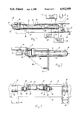
- FIG. 1 is a view of a conveyor apparatus mounted between the upper and lower die shoes of a press, adjacent the pick-up position of the blank;
- FIG. 2 is a view similar to FIG. 1, but showing an alternative means for mounting the conveyor on the lower die shoe;
- FIG. 3 is a view generally as seen from the left side of FIG. 1;
- FIG. 4 is a plan view of the preferred conveyor apparatus mounted in a press.
- a conventional press apparatus 8 having an upper die shoe 10 and a lower die shoe 12.
- the upper die shoe is raised and lowered in the conventional manner by power press ram means 14 for performing a cutting operation on magnetically-attractive sheet metal 16.
- the power means raises the upper die shoe to permit sheet metal 16 to be advanced to a cutting position in the press.
- the upper die shoe is raised in the direction of arrow 18 (FIG. 1) and then lowered in a power stroke in the direction of arrow 20 toward the lower die shoe.
- the sheet metal is fed from a coil, not shown, from the bottom side of FIG. 2 and then advanced in the direction of arrow 22.
- a pair of conventional cutting means 24 and 26 carried on the upper and lower die shoes, respectively, cut the sheet metal to form a blank with the configuration illustrated at 30 in FIG. 4.
- the blank, formed from the sheet metal, is then removed toward the left, as viewed in FIGS. 1 and 4, by conveyor apparatus, generally indicated at 32.
- the conveyor apparatus includes a pair of brackets 40 and 42 attached by fastener means 46 and 48, respectively, to the lower die shoe.
- An elongated bridge structure 50 has its ends attached to brackets 40 and 42.
- An electrically-actuated motor 52 is mounted on the midsection of the bridge structure. The motor is connected to gear box 53 which has an output shaft 54 drivingly connected by chain and sprocket means 56 to drive shaft 58.
- One end of shaft 58 is drivingly connected to a conveyor pulley 60, and the opposite end of the shaft is drivingly connected to a conveyor pulley 62.
- Conveyor shaft 58 is supported on four bearing means 64, 66, 68, and 70.
- a support structure 72 is carried on the bridge and supported in a cantilever fashion between the upper and lower die shoes, as best illustrated in FIGS. 1 and 4.
- the support structure carries an elongated conveyor support means 74 and 76.
- Conveyor pulley 60 is mounted on drive shaft 58, and a second conveyor pulley 80 is mounted on the opposite end of support structure 76.
- a urethane belt 82 is wrapped around the two pulleys 60 and 80 to travel between the two pulleys.
- Pulley 60 is driven in the clockwise direction as viewed in FIG. 1.
- An appropriate tightening means 81 is mounted on the conveyor structure for tightening the belt in the conventional manner.
- the end of the conveyor belt wrapped around pulley 80 is inside the press, between the upper die shoe and the lower die shoe, while conveyor pulley 60 is outside the press, remote from pulley 80.
- an elongated electro-magnet means 83 is mounted on conveyor support structure 76, within the loop formed by the belt, and adjacent pulley 80.
- Power means 84 provide means for energizing and adjusting the electro-magnetic strength of magnet 83.
- An elongated permanent magnet 86 is mounted on the conveyor structure within the belt loop, between pulley 60 and electro-magnet 83.
- This conveyor structure is mounted between the pick-up position of blank 30 and the upper die shoe which carries cutting means 24.
- conveyor support structure 72 supports another pulley 90 that is remote from drive pulley 62 and 90.
- a urethane conveyor belt 92 is wrapped around pulleys 62 and 90. The distance between pulleys 90 and 62 is greater than the distance between pulleys 80 and 66.
- Tightening means 94 is adapted to tighten belt 92.
- Belt 92 is parallel to belt 82. The distance between the two belts can be adjusted as well as the respective length of the two belts to accommodate the configuration of the sheet metal blank. It is to be noted that the inner pulley of each belt is closely adjacent the cut portion of the blank.
- the second belt 92 is supported adjacent magnetic pickup means, not shown, similar to that of belt 82.
- a typical pick-up device 96F is illustrated in FIG. 1 and comprises an elongated vertical support 98 having its upper end connected in a recess 100 of the upper die shoe.
- a spring-loaded vacuum cup 102 is mounted on the lower end of member 98 so as to be resiliently moveable in a direction perpendicular to the surface of blank 30.
- Vacuum means 106 is connected to the seven vacuum cups which are arranged such that as the upper die shoe is lowered, the cups collectively engage the blank just before cutting means 24 and 26 severe the blank around is border.
- the upper die Upon completion of the cutting stroke, the upper die is raised in direction 18 thereby lifting the blank until it engages the lower horizontal sides of the two conveyor belts.
- the vacuum cups then release the blank.
- the electro-magnets are energized so as to attract the blank toward the belts.
- the belts are then driven by drive pulleys 60 and 62 and motor 52 to unload the blank from the press, in a direction at right angles to the direction 22 of the sheet metal being fed into the press.
- the steel blank approaches permanent magnet 86 which maintains the metal blank attracted to the belt.
- the electro-magnet is then de-energized.
- the strength of the electro-magnets on each of the conveyors can be adjusted to accommodate the weight and configuration of the blank. Further, the pick-up strength of the electro-magnets on the two conveyors is adjusted to eliminate any tendency of the blank to waffle as it is being lifted and carried from the press.
- the blank is then removed from the press and the operation repeated during the next blank cutting cycle, as the incoming coil end passes below the outgoing blank.
- FIG. 3 illustrates how bracket means 40-42 support the bridge structure 50 to the lower die shoe 12 of the press.
Abstract
Description
Claims (16)
Priority Applications (2)
| Application Number | Priority Date | Filing Date | Title |
|---|---|---|---|
| US07/262,739 US4912959A (en) | 1988-10-26 | 1988-10-26 | Overhead magnetic blank unloading conveyor |
| CA 596419 CA1326691C (en) | 1988-10-26 | 1989-04-12 | Overhead magnetic blank unloading conveyor |
Applications Claiming Priority (1)
| Application Number | Priority Date | Filing Date | Title |
|---|---|---|---|
| US07/262,739 US4912959A (en) | 1988-10-26 | 1988-10-26 | Overhead magnetic blank unloading conveyor |
Publications (1)
| Publication Number | Publication Date |
|---|---|
| US4912959A true US4912959A (en) | 1990-04-03 |
Family
ID=22998824
Family Applications (1)
| Application Number | Title | Priority Date | Filing Date |
|---|---|---|---|
| US07/262,739 Expired - Fee Related US4912959A (en) | 1988-10-26 | 1988-10-26 | Overhead magnetic blank unloading conveyor |
Country Status (2)
| Country | Link |
|---|---|
| US (1) | US4912959A (en) |
| CA (1) | CA1326691C (en) |
Cited By (9)
| Publication number | Priority date | Publication date | Assignee | Title |
|---|---|---|---|---|
| US6182547B1 (en) | 1999-03-08 | 2001-02-06 | Irvin D. Bond | Unloader conveyor for a blanking die |
| EP1243357A2 (en) * | 2001-03-19 | 2002-09-25 | Aida Engineering Co., Ltd. | Material transport device |
| US20040248277A1 (en) * | 2001-05-23 | 2004-12-09 | Moya Garcia Jose Julio | Machine for transporting and stacking magnetic and non-magnetic sheets |
| US7891226B2 (en) | 2004-03-08 | 2011-02-22 | Enview Technologies, Llc | Electromagnetic blank restrainer |
| US20130125721A1 (en) * | 2010-08-06 | 2013-05-23 | Giuseppe Gallucci | Device for unloading flat articles from a work plane, flat articles including portions on which designs and/or writing is reproduced by cutting and/or incision |
| CN103978088A (en) * | 2014-05-26 | 2014-08-13 | 浙江恒立数控科技股份有限公司 | Metal sheet shearing machine |
| CN106216548A (en) * | 2016-08-31 | 2016-12-14 | 天津甘泉集团有限公司 | A kind of steel-plate cutter of lifting materials automatically |
| US20180290199A1 (en) * | 2014-05-09 | 2018-10-11 | Honda Motor Co., Ltd. | Blanking die and method of blanking sheet metal therewith |
| CN110899430A (en) * | 2019-11-29 | 2020-03-24 | 台州弘锐精密机械有限公司 | Stamping forming system for manufacturing electrical control cabinet metal plate panel |
Citations (4)
| Publication number | Priority date | Publication date | Assignee | Title |
|---|---|---|---|---|
| US2867185A (en) * | 1955-12-15 | 1959-01-06 | Lobdell Emery Mfg Company | Transfer mechanism |
| US2976753A (en) * | 1956-06-05 | 1961-03-28 | Fowler Alexander | Press unloader including magnetic lift means and magnetic delivery rollers |
| US3505918A (en) * | 1966-06-21 | 1970-04-14 | Willy Schneider | Apparatus for die-cutting blanks from a pile of sheet material |
| US3847269A (en) * | 1973-09-04 | 1974-11-12 | Bucciconi Eng Co | Magnetic rail type conveyor unit |
-
1988
- 1988-10-26 US US07/262,739 patent/US4912959A/en not_active Expired - Fee Related
-
1989
- 1989-04-12 CA CA 596419 patent/CA1326691C/en not_active Expired - Fee Related
Patent Citations (4)
| Publication number | Priority date | Publication date | Assignee | Title |
|---|---|---|---|---|
| US2867185A (en) * | 1955-12-15 | 1959-01-06 | Lobdell Emery Mfg Company | Transfer mechanism |
| US2976753A (en) * | 1956-06-05 | 1961-03-28 | Fowler Alexander | Press unloader including magnetic lift means and magnetic delivery rollers |
| US3505918A (en) * | 1966-06-21 | 1970-04-14 | Willy Schneider | Apparatus for die-cutting blanks from a pile of sheet material |
| US3847269A (en) * | 1973-09-04 | 1974-11-12 | Bucciconi Eng Co | Magnetic rail type conveyor unit |
Cited By (13)
| Publication number | Priority date | Publication date | Assignee | Title |
|---|---|---|---|---|
| US6182547B1 (en) | 1999-03-08 | 2001-02-06 | Irvin D. Bond | Unloader conveyor for a blanking die |
| EP1243357A2 (en) * | 2001-03-19 | 2002-09-25 | Aida Engineering Co., Ltd. | Material transport device |
| EP1243357A3 (en) * | 2001-03-19 | 2004-04-28 | Aida Engineering Co., Ltd. | Material transport device |
| US20040248277A1 (en) * | 2001-05-23 | 2004-12-09 | Moya Garcia Jose Julio | Machine for transporting and stacking magnetic and non-magnetic sheets |
| US7891226B2 (en) | 2004-03-08 | 2011-02-22 | Enview Technologies, Llc | Electromagnetic blank restrainer |
| US20130125721A1 (en) * | 2010-08-06 | 2013-05-23 | Giuseppe Gallucci | Device for unloading flat articles from a work plane, flat articles including portions on which designs and/or writing is reproduced by cutting and/or incision |
| US8915171B2 (en) * | 2010-08-06 | 2014-12-23 | Giuseppe Gallucci | Device for unloading flat articles from a work plane, flat articles including portions on which designs and/or writing is reproduced by cutting and/or incision |
| US20180290199A1 (en) * | 2014-05-09 | 2018-10-11 | Honda Motor Co., Ltd. | Blanking die and method of blanking sheet metal therewith |
| US10596617B2 (en) * | 2014-05-09 | 2020-03-24 | Honda Motor Co., Ltd. | Blanking die and method of blanking sheet metal therewith |
| CN103978088A (en) * | 2014-05-26 | 2014-08-13 | 浙江恒立数控科技股份有限公司 | Metal sheet shearing machine |
| CN103978088B (en) * | 2014-05-26 | 2016-05-11 | 浙江恒立数控科技股份有限公司 | A kind of sheet metal cutter |
| CN106216548A (en) * | 2016-08-31 | 2016-12-14 | 天津甘泉集团有限公司 | A kind of steel-plate cutter of lifting materials automatically |
| CN110899430A (en) * | 2019-11-29 | 2020-03-24 | 台州弘锐精密机械有限公司 | Stamping forming system for manufacturing electrical control cabinet metal plate panel |
Also Published As
| Publication number | Publication date |
|---|---|
| CA1326691C (en) | 1994-02-01 |
Similar Documents
| Publication | Publication Date | Title |
|---|---|---|
| US4912959A (en) | Overhead magnetic blank unloading conveyor | |
| CZ291260B6 (en) | Vacuum-based device for transporting suspended flat parts, such as sheets, plates, sheet or plate articles, and the like flat goods | |
| US3584866A (en) | Magnetic conveyor | |
| JPH0569944A (en) | Automatic steel carrier device | |
| US4452351A (en) | Sheet handling apparatus | |
| CN107953137B (en) | Intelligent work piece process equipment | |
| US5460480A (en) | Installation for handling the conveyance of blanks from a cutting machine to a stacking device | |
| KR102399131B1 (en) | Blanking product high-speed loading and transfer device with high-speed sorting device | |
| US6182547B1 (en) | Unloader conveyor for a blanking die | |
| CN205765184U (en) | Intelligent work piece process equipment | |
| CN211803496U (en) | Belt conveyor line with magnetic wire end | |
| CN210614907U (en) | Punch machining center | |
| US2499439A (en) | Sheet feeding and separating device | |
| CN110510396B (en) | Automatic unloading equipment of going up of hardware | |
| JPS6313873Y2 (en) | ||
| US4452353A (en) | Apparatus for separating stacks placed on stack feed conveyor | |
| JP2564228Y2 (en) | Plate processing machine with storage | |
| RU2138356C1 (en) | Apparatus for moving sheet blanks to press zone | |
| CN213887928U (en) | Full-automatic intelligent vision feeder | |
| CN214002985U (en) | Automatic change transport assembly of production structure | |
| US3224565A (en) | Method and apparatus for conveying objects | |
| JPH05259Y2 (en) | ||
| CN210214086U (en) | Conveying mechanism for glass production and processing | |
| JPH085171Y2 (en) | Plate-shaped work delivery device | |
| JP2591652Y2 (en) | Plate unloading device |
Legal Events
| Date | Code | Title | Description |
|---|---|---|---|
| FPAY | Fee payment |
Year of fee payment: 4 |
|
| AS | Assignment |
Owner name: DCT AUTOMATION, INC., MICHIGAN Free format text: ASSIGNMENT OF ASSIGNORS INTEREST;ASSIGNORS:BOND ROBOTICS, INC.;BOND, IRVIN DALE;REEL/FRAME:007613/0888 Effective date: 19950602 |
|
| FEPP | Fee payment procedure |
Free format text: PAT HLDR NO LONGER CLAIMS SMALL ENT STAT AS INDIV INVENTOR (ORIGINAL EVENT CODE: LSM1); ENTITY STATUS OF PATENT OWNER: LARGE ENTITY |
|
| FPAY | Fee payment |
Year of fee payment: 8 |
|
| SULP | Surcharge for late payment | ||
| REMI | Maintenance fee reminder mailed | ||
| LAPS | Lapse for failure to pay maintenance fees | ||
| STCH | Information on status: patent discontinuation |
Free format text: PATENT EXPIRED DUE TO NONPAYMENT OF MAINTENANCE FEES UNDER 37 CFR 1.362 |
|
| FP | Lapsed due to failure to pay maintenance fee |
Effective date: 20020403 |