US4910987A - Roll neck face seal for cantilevered rolling mill - Google Patents
Roll neck face seal for cantilevered rolling mill Download PDFInfo
- Publication number
- US4910987A US4910987A US07/316,488 US31648889A US4910987A US 4910987 A US4910987 A US 4910987A US 31648889 A US31648889 A US 31648889A US 4910987 A US4910987 A US 4910987A
- Authority
- US
- United States
- Prior art keywords
- seal
- housing
- shaft
- contact surface
- circular
- Prior art date
- Legal status (The legal status is an assumption and is not a legal conclusion. Google has not performed a legal analysis and makes no representation as to the accuracy of the status listed.)
- Expired - Lifetime
Links
- 238000005096 rolling process Methods 0.000 title claims abstract description 11
- 238000007789 sealing Methods 0.000 claims abstract description 13
- 238000013022 venting Methods 0.000 claims 2
- 238000005452 bending Methods 0.000 description 4
- 239000000498 cooling water Substances 0.000 description 4
- 230000009977 dual effect Effects 0.000 description 4
- 239000000314 lubricant Substances 0.000 description 4
- 230000004323 axial length Effects 0.000 description 3
- 230000000712 assembly Effects 0.000 description 1
- 238000000429 assembly Methods 0.000 description 1
- 239000011324 bead Substances 0.000 description 1
- 239000000356 contaminant Substances 0.000 description 1
- -1 e.g. Substances 0.000 description 1
- 239000012530 fluid Substances 0.000 description 1
- 238000012423 maintenance Methods 0.000 description 1
- 239000000463 material Substances 0.000 description 1
- 230000007246 mechanism Effects 0.000 description 1
- 239000002184 metal Substances 0.000 description 1
- 230000004048 modification Effects 0.000 description 1
- 238000012986 modification Methods 0.000 description 1
- 230000000149 penetrating effect Effects 0.000 description 1
Images


Classifications
-
- F—MECHANICAL ENGINEERING; LIGHTING; HEATING; WEAPONS; BLASTING
- F16—ENGINEERING ELEMENTS AND UNITS; GENERAL MEASURES FOR PRODUCING AND MAINTAINING EFFECTIVE FUNCTIONING OF MACHINES OR INSTALLATIONS; THERMAL INSULATION IN GENERAL
- F16J—PISTONS; CYLINDERS; SEALINGS
- F16J15/00—Sealings
- F16J15/16—Sealings between relatively-moving surfaces
- F16J15/34—Sealings between relatively-moving surfaces with slip-ring pressed against a more or less radial face on one member
- F16J15/3436—Pressing means
- F16J15/3456—Pressing means without external means for pressing the ring against the face, e.g. slip-ring with a resilient lip
-
- B—PERFORMING OPERATIONS; TRANSPORTING
- B21—MECHANICAL METAL-WORKING WITHOUT ESSENTIALLY REMOVING MATERIAL; PUNCHING METAL
- B21B—ROLLING OF METAL
- B21B31/00—Rolling stand structures; Mounting, adjusting, or interchanging rolls, roll mountings, or stand frames
- B21B31/07—Adaptation of roll neck bearings
- B21B31/078—Sealing devices
-
- B—PERFORMING OPERATIONS; TRANSPORTING
- B21—MECHANICAL METAL-WORKING WITHOUT ESSENTIALLY REMOVING MATERIAL; PUNCHING METAL
- B21B—ROLLING OF METAL
- B21B13/00—Metal-rolling stands, i.e. an assembly composed of a stand frame, rolls, and accessories
- B21B13/005—Cantilevered roll stands
-
- B—PERFORMING OPERATIONS; TRANSPORTING
- B21—MECHANICAL METAL-WORKING WITHOUT ESSENTIALLY REMOVING MATERIAL; PUNCHING METAL
- B21B—ROLLING OF METAL
- B21B31/00—Rolling stand structures; Mounting, adjusting, or interchanging rolls, roll mountings, or stand frames
- B21B31/16—Adjusting or positioning rolls
- B21B31/20—Adjusting or positioning rolls by moving rolls perpendicularly to roll axis
- B21B31/22—Adjusting or positioning rolls by moving rolls perpendicularly to roll axis mechanically, e.g. by thrust blocks, inserts for removal
- B21B31/26—Adjusting eccentrically-mounted roll bearings
-
- F—MECHANICAL ENGINEERING; LIGHTING; HEATING; WEAPONS; BLASTING
- F16—ENGINEERING ELEMENTS AND UNITS; GENERAL MEASURES FOR PRODUCING AND MAINTAINING EFFECTIVE FUNCTIONING OF MACHINES OR INSTALLATIONS; THERMAL INSULATION IN GENERAL
- F16C—SHAFTS; FLEXIBLE SHAFTS; ELEMENTS OR CRANKSHAFT MECHANISMS; ROTARY BODIES OTHER THAN GEARING ELEMENTS; BEARINGS
- F16C13/00—Rolls, drums, discs, or the like; Bearings or mountings therefor
- F16C13/02—Bearings
-
- F—MECHANICAL ENGINEERING; LIGHTING; HEATING; WEAPONS; BLASTING
- F16—ENGINEERING ELEMENTS AND UNITS; GENERAL MEASURES FOR PRODUCING AND MAINTAINING EFFECTIVE FUNCTIONING OF MACHINES OR INSTALLATIONS; THERMAL INSULATION IN GENERAL
- F16C—SHAFTS; FLEXIBLE SHAFTS; ELEMENTS OR CRANKSHAFT MECHANISMS; ROTARY BODIES OTHER THAN GEARING ELEMENTS; BEARINGS
- F16C2322/00—Apparatus used in shaping articles
- F16C2322/12—Rolling apparatus, e.g. rolling stands, rolls
-
- F—MECHANICAL ENGINEERING; LIGHTING; HEATING; WEAPONS; BLASTING
- F16—ENGINEERING ELEMENTS AND UNITS; GENERAL MEASURES FOR PRODUCING AND MAINTAINING EFFECTIVE FUNCTIONING OF MACHINES OR INSTALLATIONS; THERMAL INSULATION IN GENERAL
- F16C—SHAFTS; FLEXIBLE SHAFTS; ELEMENTS OR CRANKSHAFT MECHANISMS; ROTARY BODIES OTHER THAN GEARING ELEMENTS; BEARINGS
- F16C33/00—Parts of bearings; Special methods for making bearings or parts thereof
- F16C33/72—Sealings
- F16C33/74—Sealings of sliding-contact bearings
Definitions
- This invention relates generally to so called “cantilevered” rolling mills, where the work rolls are mounted in an overhung fashion on the ends of roll shafts which protrude from housings containing the shaft bearings, gears, roll parting adjustment mechanisms, etc.
- the invention is concerned in particular with an improved dual lip shaft seal assembly for preventing leakage of lubricants from such housings and for preventing ingress of external contaminants, e.g., cooling water and entrained dirt, mill scale, etc.
- FIGS. 1 and 2 are illustrative of a typical prior art mill and shaft seal arrangement.
- Roll shafts 10 are journalled between sleeve bearings 12 supported in rotatable eccentrics 14a, 14b.
- the eccentrics in turn are journalled respectively for rotation in the front and rear plates 16a, 16b of a housing 18.
- the roll shafts 10 carry gears 20 which mesh with other gears (not shown) forming part of the mill drive.
- the roll shafts have ends protruding externally through the front housing plate 16a. These protruding ends include truncated conical portions 10, on which grooved work rolls 22 are removably secured by means of tapered sleeves 24 axially wedged therebetween. Transversely extending keys 26 bear against the outboard flanks of the rolls and are held in place by set screws 28 threaded into the ends of the roll shafts. Covers 30 enclose the keys 26 and the outboard ends of the sleeves 24. The covers are held in place by caps 32 threaded onto the shaft ends. Simultaneous rotation of each roll shaft's eccentrics 14a, 14b in opposite directions serves to symmetrically adjust the roll shafts and the work rolls carried thereon with respect to the mill pass line.
- each seal assembly 34 serves to retain the lubricant within the housing while at the same time excluding cooling water and entrained mill scale, dirt, etc. from penetrating into the housing interior.
- each seal assembly 34 includes a pair of metal flingers 36, 38 surrounding the roll shaft and interposed between the inboard flank of the work roll 22 and the respective adjacent shaft bearing 12 and eccentric 14a.
- the flingers have generally L-shaped cross-sectional configurations, with abutting base portions 36a, 38a and with radially extending axially spaced flanges 36b, 38b defining confronting annular contact surfaces 36c, 38c.
- the flinger base portions are supported on a cylindrical land L a machined into the shaft surface at a location between the larger diameter portion journalled for rotation in the adjacent bearing 12 and the truncated conical portion 10' on which the work roll 22 is removably mounted by the tapered sleeve 24 interposed therebetween.
- Land L a has an axial length l a .
- a seal end plate 40 is fastened to the housing end plate 16a.
- the seal end plate has a pair of openings 42 through which the roll shafts protrude.
- the openings 42 are concentric with the rotational axes of the eccentric bearing sleeves 14a.
- Seal holders 44 are journalled for rotation in the openings 42, and are mechanically tied to the eccentric sleeves 14a for rotation therewith by means of machine screws 46 or the like.
- the seal holders have inwardly extending radial flanges 44' surrounding the roll shafts.
- the inner rims of the flanges 44' are grooved as at 44" to receive circular radially outwardly protruding beads on the base portions of seals 48 having dual oppositely facing axially separated lips 48a, 48b.
- the inner edges of the flanges 44' and the seals 48 mounted thereon are arranged coaxially with the rotational axes of the roll shafts.
- the flingers 36, 38 rotate with the roll shafts, and the seals 48 remain fixed in relation to their respective seal holders 44, the latter being tied to the eccentric sleeves 14a which only are rotated to achieve adjustment of the roll parting.
- Contact between the outboard seal lip 48a and contact surface 36c serves to exclude cooling water and entrained particulates from the housing interior, whereas contact between the inboard seal lip 48b and contact surface 38c serves to retain lubricants within the housing.
- the present invention retains the dual lip sealing capability of the prior art arrangement.
- the seal lips are reoriented into a radially spaced arrangement in sealing contact with a common annular contact surface on a single flinger.
- the single flinger occupies a substantially shorter cylindrical land on the roll shaft, thereby markedly reducing stresses experienced as the roll shafts undergo separating forces during rolling. This in turn translates into an ability to roll under much higher loads.
- FIG. 1 is a cross-sectional view through a typical cantilevered rolling mill with prior art seals employed on the roll shafts;
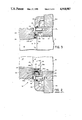
- FIG. 2 is an enlarged partial sectional view of a portion of the arrangement shown in FIG. 1, and illustrating the prior art seal in greater detail;
- FIG. 3 is a view similar to FIG. 2 showing the seal arrangement of the present invention
- FIG. 4 is a greatly enlarged view of a portion of FIG. 3;
- FIG. 5 is a side elevational view of a flexible seal of the type illustrated in FIGS. 3 and 4;
- FIG. 6 is a sectional view taken along line 6--6 of FIG. 4;
- FIG. 7 is a cross-sectional view on an enlarged scale taken through the flexible seal of FIGS. 3-6;
- FIG. 8 is a view similar to FIG. 7 shown an alternate embodiment of the flexible seal.
- FIG. 9 is a diagrammatic illustration of separating forces and resulting bending moments experienced by the roll shaft during rolling.
- FIGS. 3 and 4 wherein the same reference numerals have been employed to designate components which are common to the prior art arrangement shown in FIGS. 1 and 2, it will be seen that the present invention employs a single flinger 36 which is again provided with an L-shaped configuration having a cylindrical base portion 36a and a radial flange portion 36b defining an annular contact surface 36c facing in the direction of the housing.
- the base portion 36a is seated on a cylindrical shaft l and L b having an axial length l b .
- the seal holder 44 is mounted for rotation within the seal end plate 40, is tied to the eccentric sleeve 14a by means of a connecting screw or pin 46, and is provided with an inwardly extending radial flange 44'.
- the groove 44" has been shifted to a position facing the contact face 36c to accommodate introduction of a totally redesigned flexible seal 50.
- seal 50 includes a circular base 52 with inner and outer cylindrical surfaces 50a, 50b interrupted by circular ribs 54, and with a circular groove 56 at one end thereof.
- a pair of lips 58, 60 extend from the opposite end of the base 52.
- Lip 56 comprises a truncated conical web 56a extending angularly outwardly to a rounded edge 56b
- lip 58 likewise comprises a truncated conical web 58a extending angularly inwardly to a rounded edge 58b.
- the circular base 52 is provided at 180° intervals with thickened portions, one of which is illustrated in FIG. 6.
- the thickened portions are defined by bosses 62a, 62b respectively protruding radially inwardly and outwardly from cylindrical surfaces 50a, 50b.
- a passageway 64 extends through each thickened portion of the base.
- the base 52 is configured and dimensioned to be received in the groove 44" of the seal holder, with its lips 56b, 58b spread apart (compare FIGS. 4 and 7) into sealing contact with the contact surface 36c of the flinger 36. Sealing contact thus occurs along inner and outer radially spaced circular lines.
- bosses 62a, 62b respectively extend across the contact interfaces of surfaces 50a, 50b with the adjacent interior surfaces of the groove 44" into recesses in those interior groove surfaces to provide an interlock which effectively prevents rotation of the seal relative to the seal holder.
- the lips 56, 58 cooperate with the annular contact surface 36c in defining an annular chamber 66 surrounding the roll shaft.
- the passageways 64 in the seal base communicate with passageways 68, 70 in the seal holder to vent the chamber 66, thus preventing pressure or vacuum conditions to build up as a result of temperature fluctuations during rolling.
- a pressure condition in chamber 66 might tend to lift the lips 56, 58 off the contact surface 36c and thus jeopardize sealing integrity.
- a vacuum build up might tend to pull the lips harder against the same surface, thereby increasing friction and wear.
- a further advantage of the present invention is that when the work roll 22 and flinger 35 are removed from the shaft, both seal lips 56, 58 are fully and equally visible for examination by maintenance personnel.
- FIG. 8 illustrates an alternate embodiment of the seal which is identical to that shown in FIG. 7, except that here the edges 56b', 58b' of the lips 56, 58 are sharpened rathe than rounded. It is believed that this modification may prove to be advantageous in eliminating or at least minimizing the entrapment and build up of fluids between the seal lips and the flinger contact surface.
Abstract
Description
Claims (8)
Priority Applications (1)
| Application Number | Priority Date | Filing Date | Title |
|---|---|---|---|
| US07/316,488 US4910987A (en) | 1989-02-27 | 1989-02-27 | Roll neck face seal for cantilevered rolling mill |
Applications Claiming Priority (1)
| Application Number | Priority Date | Filing Date | Title |
|---|---|---|---|
| US07/316,488 US4910987A (en) | 1989-02-27 | 1989-02-27 | Roll neck face seal for cantilevered rolling mill |
Publications (1)
| Publication Number | Publication Date |
|---|---|
| US4910987A true US4910987A (en) | 1990-03-27 |
Family
ID=23229265
Family Applications (1)
| Application Number | Title | Priority Date | Filing Date |
|---|---|---|---|
| US07/316,488 Expired - Lifetime US4910987A (en) | 1989-02-27 | 1989-02-27 | Roll neck face seal for cantilevered rolling mill |
Country Status (1)
| Country | Link |
|---|---|
| US (1) | US4910987A (en) |
Cited By (12)
| Publication number | Priority date | Publication date | Assignee | Title |
|---|---|---|---|---|
| EP0850703A1 (en) * | 1996-12-23 | 1998-07-01 | Sms Schloemann-Siemag Aktiengesellschaft | Wire rolling stand |
| US6053502A (en) * | 1995-01-13 | 2000-04-25 | Ab Volvo Penta | Seat for a sealing ring |
| EP1038601A2 (en) * | 1999-03-23 | 2000-09-27 | Kvaerner Metals Davy Limited | Sealing assembly |
| WO2005061139A1 (en) * | 2003-12-16 | 2005-07-07 | Sms Demag Ag | Sealing device |
| US20050151449A1 (en) * | 2004-01-09 | 2005-07-14 | Fanuc Ltd | Multistage Oil Seal For Machine Tool Motor |
| WO2012012077A1 (en) | 2010-07-22 | 2012-01-26 | Siemens Industry, Inc. | Seal assembly |
| CN105570467A (en) * | 2016-03-24 | 2016-05-11 | 衡水哈西特液压机械有限公司 | Sealing member of high-speed wire rolling mill |
| CN105865209A (en) * | 2016-05-27 | 2016-08-17 | 山东钢铁股份有限公司 | Water cooling cantilever roller way for steel billet heating furnace |
| US20180243747A1 (en) * | 2015-03-18 | 2018-08-30 | Pms Handelskontor Gmbh | Comminuting device |
| WO2022063615A1 (en) * | 2020-09-28 | 2022-03-31 | Sms Group Gmbh | Roller assembly |
| US20220252108A1 (en) * | 2021-02-08 | 2022-08-11 | Goodrich Actuation Systems Limited | Thrust bearing seal for thin wing multi slice rga |
| CN116984378A (en) * | 2023-08-25 | 2023-11-03 | 汉威广园(广州)机械设备有限公司 | Eccentric sleeve assembly and rolling mill with same |
Citations (4)
| Publication number | Priority date | Publication date | Assignee | Title |
|---|---|---|---|---|
| US4022480A (en) * | 1975-10-07 | 1977-05-10 | Morgan Construction Company | Neck seal |
| US4234196A (en) * | 1979-02-21 | 1980-11-18 | Nippon Oil Seal Industry Co., Ltd. | Roll neck sealing device |
| JPS6112130A (en) * | 1984-06-27 | 1986-01-20 | Hitachi Ltd | Pcm coder and decoder |
| US4586720A (en) * | 1985-01-23 | 1986-05-06 | Morgan Construction Company | Neck seal |
-
1989
- 1989-02-27 US US07/316,488 patent/US4910987A/en not_active Expired - Lifetime
Patent Citations (4)
| Publication number | Priority date | Publication date | Assignee | Title |
|---|---|---|---|---|
| US4022480A (en) * | 1975-10-07 | 1977-05-10 | Morgan Construction Company | Neck seal |
| US4234196A (en) * | 1979-02-21 | 1980-11-18 | Nippon Oil Seal Industry Co., Ltd. | Roll neck sealing device |
| JPS6112130A (en) * | 1984-06-27 | 1986-01-20 | Hitachi Ltd | Pcm coder and decoder |
| US4586720A (en) * | 1985-01-23 | 1986-05-06 | Morgan Construction Company | Neck seal |
Cited By (19)
| Publication number | Priority date | Publication date | Assignee | Title |
|---|---|---|---|---|
| US6053502A (en) * | 1995-01-13 | 2000-04-25 | Ab Volvo Penta | Seat for a sealing ring |
| EP0850703A1 (en) * | 1996-12-23 | 1998-07-01 | Sms Schloemann-Siemag Aktiengesellschaft | Wire rolling stand |
| EP1038601A2 (en) * | 1999-03-23 | 2000-09-27 | Kvaerner Metals Davy Limited | Sealing assembly |
| EP1038601A3 (en) * | 1999-03-23 | 2003-12-10 | Kvaerner Engineering & Construction UK Limited | Sealing assembly |
| US7549647B2 (en) | 2003-12-16 | 2009-06-23 | Sms Demag Ag | Sealing device |
| CN1894055B (en) * | 2003-12-16 | 2012-10-24 | Sms西马格股份公司 | Sealing device |
| US20070140601A1 (en) * | 2003-12-16 | 2007-06-21 | Konrad Roeingh | Sealing device |
| WO2005061139A1 (en) * | 2003-12-16 | 2005-07-07 | Sms Demag Ag | Sealing device |
| US7182346B2 (en) * | 2004-01-09 | 2007-02-27 | Fanuc Ltd | Multistage oil seal against different cutting fluids for a machine tool motor |
| US20050151449A1 (en) * | 2004-01-09 | 2005-07-14 | Fanuc Ltd | Multistage Oil Seal For Machine Tool Motor |
| US8740462B2 (en) | 2010-07-22 | 2014-06-03 | Siemens Industry, Inc. | Seal assembly |
| WO2012012077A1 (en) | 2010-07-22 | 2012-01-26 | Siemens Industry, Inc. | Seal assembly |
| US20180243747A1 (en) * | 2015-03-18 | 2018-08-30 | Pms Handelskontor Gmbh | Comminuting device |
| US10639639B2 (en) * | 2015-03-18 | 2020-05-05 | Pms Handelskontor Gmbh | Comminuting device |
| CN105570467A (en) * | 2016-03-24 | 2016-05-11 | 衡水哈西特液压机械有限公司 | Sealing member of high-speed wire rolling mill |
| CN105865209A (en) * | 2016-05-27 | 2016-08-17 | 山东钢铁股份有限公司 | Water cooling cantilever roller way for steel billet heating furnace |
| WO2022063615A1 (en) * | 2020-09-28 | 2022-03-31 | Sms Group Gmbh | Roller assembly |
| US20220252108A1 (en) * | 2021-02-08 | 2022-08-11 | Goodrich Actuation Systems Limited | Thrust bearing seal for thin wing multi slice rga |
| CN116984378A (en) * | 2023-08-25 | 2023-11-03 | 汉威广园(广州)机械设备有限公司 | Eccentric sleeve assembly and rolling mill with same |
Similar Documents
| Publication | Publication Date | Title |
|---|---|---|
| US4910987A (en) | Roll neck face seal for cantilevered rolling mill | |
| CA1092631A (en) | Means for lubricating the roll neck/sleeve interface of an oil film bearing | |
| CA2536729C (en) | Journal bearing backing ring | |
| US4527915A (en) | Sealed multi-row roller bearing device for rolling mills | |
| US4630458A (en) | Seal arrangement for mill roll | |
| EP0697533A1 (en) | Compact bearing and stiffened journal | |
| EP2760600B1 (en) | Rolling stand roll neck seal | |
| EP1070556B1 (en) | Bushing for oil film bearing | |
| US4669760A (en) | Swivel fitting arrangement for use in a pressurized fluid line | |
| GB2264757A (en) | A multi-row roller bearing. | |
| US5118206A (en) | Cone bore seal | |
| AU675723B2 (en) | Interlocked seal and sleeve for rolling mill oil film bearing | |
| US4063743A (en) | Sealing arrangement for a rotatable member | |
| CA1292031C (en) | Roll neck bearing assembly and inner bearing component therefor | |
| EP1447149B1 (en) | Seal end plate | |
| JPS6128799B2 (en) | ||
| US3892446A (en) | Shaft seal | |
| US4687350A (en) | Sealed bearing for ring roller of cold pilger rolling mill | |
| US3945693A (en) | Track roller | |
| GB1575730A (en) | Flexible seal and seal assembly | |
| US4875261A (en) | Back-up roll in a rolling mill | |
| US3884535A (en) | Seal | |
| RU2309016C2 (en) | Sealing device having annular body of two parts | |
| WO2002038428A1 (en) | Stabilized seal wear ring | |
| CN213039815U (en) | Roller distance sealing device |
Legal Events
| Date | Code | Title | Description |
|---|---|---|---|
| AS | Assignment |
Owner name: MORGAN CONSTRUCTION COMPANY, MASSACHUSETTS Free format text: ASSIGNMENT OF ASSIGNORS INTEREST.;ASSIGNOR:WOODROW, HAROLD E.;REEL/FRAME:005049/0916 Effective date: 19890220 |
|
| STCF | Information on status: patent grant |
Free format text: PATENTED CASE |
|
| FEPP | Fee payment procedure |
Free format text: PAT HOLDER CLAIMS SMALL ENTITY STATUS - SMALL BUSINESS (ORIGINAL EVENT CODE: SM02); ENTITY STATUS OF PATENT OWNER: LARGE ENTITY |
|
| REMI | Maintenance fee reminder mailed | ||
| FPAY | Fee payment |
Year of fee payment: 4 |
|
| SULP | Surcharge for late payment | ||
| FEPP | Fee payment procedure |
Free format text: PAYOR NUMBER ASSIGNED (ORIGINAL EVENT CODE: ASPN); ENTITY STATUS OF PATENT OWNER: LARGE ENTITY |
|
| REFU | Refund |
Free format text: REFUND OF EXCESS PAYMENTS PROCESSED (ORIGINAL EVENT CODE: R169); ENTITY STATUS OF PATENT OWNER: LARGE ENTITY |
|
| REFU | Refund |
Free format text: REFUND OF EXCESS PAYMENTS PROCESSED (ORIGINAL EVENT CODE: R169); ENTITY STATUS OF PATENT OWNER: LARGE ENTITY |
|
| AS | Assignment |
Owner name: FIRST NATIONAL BANK OF BOSTON, THE, MASSACHUSETTS Free format text: SECURITY INTEREST;ASSIGNOR:MORGAN CONSTRUCTION COMPANY;REEL/FRAME:007327/0055 Effective date: 19920131 |
|
| FPAY | Fee payment |
Year of fee payment: 8 |
|
| FEPP | Fee payment procedure |
Free format text: PAYOR NUMBER ASSIGNED (ORIGINAL EVENT CODE: ASPN); ENTITY STATUS OF PATENT OWNER: LARGE ENTITY Free format text: PAYER NUMBER DE-ASSIGNED (ORIGINAL EVENT CODE: RMPN); ENTITY STATUS OF PATENT OWNER: LARGE ENTITY |
|
| FEPP | Fee payment procedure |
Free format text: PAT HLDR NO LONGER CLAIMS SMALL ENT STAT AS SMALL BUSINESS (ORIGINAL EVENT CODE: LSM2); ENTITY STATUS OF PATENT OWNER: LARGE ENTITY |
|
| FPAY | Fee payment |
Year of fee payment: 12 |
|
| AS | Assignment |
Owner name: MORGAN CONSTRUCTION COMPANY, MASSACHUSETTS Free format text: RELEASE BY SECURED PARTY;ASSIGNOR:BANK OF AMERICA, N.A., SUCCESSOR-IN-INTEREST TO FLEET NATIONAL BANK, N.A., SUCCESSOR-IN-INTEREST TO FIRST NATIONAL BANK OF BOSTON, AND SUCCESSOR-IN-INTEREST TO WORCESTER COUNTY INSTITUTION FOR SAVINGS;REEL/FRAME:020733/0331 Effective date: 20080331 |