US4901927A - Dual shower head assembly - Google Patents
Dual shower head assembly Download PDFInfo
- Publication number
- US4901927A US4901927A US07/309,832 US30983289A US4901927A US 4901927 A US4901927 A US 4901927A US 30983289 A US30983289 A US 30983289A US 4901927 A US4901927 A US 4901927A
- Authority
- US
- United States
- Prior art keywords
- water
- shower head
- diverter valve
- shower
- valve
- Prior art date
- Legal status (The legal status is an assumption and is not a legal conclusion. Google has not performed a legal analysis and makes no representation as to the accuracy of the status listed.)
- Expired - Fee Related
Links
Images
Classifications
-
- E—FIXED CONSTRUCTIONS
- E03—WATER SUPPLY; SEWERAGE
- E03C—DOMESTIC PLUMBING INSTALLATIONS FOR FRESH WATER OR WASTE WATER; SINKS
- E03C1/00—Domestic plumbing installations for fresh water or waste water; Sinks
- E03C1/02—Plumbing installations for fresh water
- E03C1/04—Water-basin installations specially adapted to wash-basins or baths
- E03C1/0408—Water installations especially for showers
-
- B—PERFORMING OPERATIONS; TRANSPORTING
- B05—SPRAYING OR ATOMISING IN GENERAL; APPLYING FLUENT MATERIALS TO SURFACES, IN GENERAL
- B05B—SPRAYING APPARATUS; ATOMISING APPARATUS; NOZZLES
- B05B1/00—Nozzles, spray heads or other outlets, with or without auxiliary devices such as valves, heating means
- B05B1/14—Nozzles, spray heads or other outlets, with or without auxiliary devices such as valves, heating means with multiple outlet openings; with strainers in or outside the outlet opening
- B05B1/16—Nozzles, spray heads or other outlets, with or without auxiliary devices such as valves, heating means with multiple outlet openings; with strainers in or outside the outlet opening having selectively- effective outlets
- B05B1/1627—Nozzles, spray heads or other outlets, with or without auxiliary devices such as valves, heating means with multiple outlet openings; with strainers in or outside the outlet opening having selectively- effective outlets with a selecting mechanism comprising a gate valve, a sliding valve or a cock
- B05B1/1636—Nozzles, spray heads or other outlets, with or without auxiliary devices such as valves, heating means with multiple outlet openings; with strainers in or outside the outlet opening having selectively- effective outlets with a selecting mechanism comprising a gate valve, a sliding valve or a cock by relative rotative movement of the valve elements
-
- E—FIXED CONSTRUCTIONS
- E03—WATER SUPPLY; SEWERAGE
- E03C—DOMESTIC PLUMBING INSTALLATIONS FOR FRESH WATER OR WASTE WATER; SINKS
- E03C2201/00—Details, devices or methods not otherwise provided for
- E03C2201/30—Diverter valves in faucets or taps
-
- Y—GENERAL TAGGING OF NEW TECHNOLOGICAL DEVELOPMENTS; GENERAL TAGGING OF CROSS-SECTIONAL TECHNOLOGIES SPANNING OVER SEVERAL SECTIONS OF THE IPC; TECHNICAL SUBJECTS COVERED BY FORMER USPC CROSS-REFERENCE ART COLLECTIONS [XRACs] AND DIGESTS
- Y10—TECHNICAL SUBJECTS COVERED BY FORMER USPC
- Y10T—TECHNICAL SUBJECTS COVERED BY FORMER US CLASSIFICATION
- Y10T137/00—Fluid handling
- Y10T137/8593—Systems
- Y10T137/877—With flow control means for branched passages
- Y10T137/87877—Single inlet with multiple distinctly valved outlets
-
- Y—GENERAL TAGGING OF NEW TECHNOLOGICAL DEVELOPMENTS; GENERAL TAGGING OF CROSS-SECTIONAL TECHNOLOGIES SPANNING OVER SEVERAL SECTIONS OF THE IPC; TECHNICAL SUBJECTS COVERED BY FORMER USPC CROSS-REFERENCE ART COLLECTIONS [XRACs] AND DIGESTS
- Y10—TECHNICAL SUBJECTS COVERED BY FORMER USPC
- Y10T—TECHNICAL SUBJECTS COVERED BY FORMER US CLASSIFICATION
- Y10T137/00—Fluid handling
- Y10T137/8593—Systems
- Y10T137/877—With flow control means for branched passages
- Y10T137/87909—Containing rotary valve
Definitions
- U.S. Pat. Nos. 3,971,074 and 3,121,235 employ a multiple number of shower heads for providing a plurality of differently angled sprays for a single person. They will not comfortably accommodate more than one person at a time and thus provide little or no water savings.
- U.S. Pat. No. 3,121,235 provides several shower heads extending from a vertically mounted pipe communicating with the shower's water supply pipe. While the individual shower heads are mounted at different heights along the vertical pipe, they do not have the flexibility necessary for convenient use by two people concurrently. The upper most head, while extending outwardly from the vertical pipe, is below the water supply pipe in the wall and thus does not provide the necessary spray angle to reach a second person within the shower enclosure.
- U.S. Pat. No. 3,971,074 provides a number of shower heads, all of which are designed to converge on a single person. Like the device of the preceding patent, this arrangement is also very intrusive into the shower area and is generally unsightly.
- the dual shower head configuration of the present invention overcomes these deficiencies and provides a space efficient, water-saving configuration highly suitable for concurrent use by two people and, if desired, two adjustable sprays for use by a single person.
- the invention comprises a versatile, water-saving shower head assembly for use in personal showers to allow two people to shower independently at the same time or one person with either a single or two separate sprays.
- the assembly includes a pair of shower heads pivotally mounted adjacent the extended ends of an upstanding substantially "S"-shaped conduit so as to define an upper shower head and a lower shower head.
- a diverter valve is disposed adjacent the lower shower head for limiting the flow of water and selectively allowing water flow either solely through the lower shower head or through both the upper and lower shower head and an adjustable flow control shut off valve is disposed between the lower shower head and the diverter valve for selectively allowing water flow to the lower shower head.
- water can be directed to spray only through the lower shower head, only through the upper shower head, through both shower heads concurrently, or through neither shower head.
- the pivotal mounting of the individual shower heads and the substantially S-shaped conduit provide a substantial flexibility in the positioning of water spray or sprays for one or two persons of varying heights.
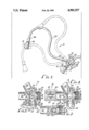
- FIG. 1 is a side view of the dual shower head assembly of the present invention mounted in a shower enclosure and illustrating the pivotal movement of the assembly in phantom lines.
- FIG. 2 is a sectional view taken along line 2--2 in FIG. 1.
- FIG. 3 is a sectional view of the diverter valve employed in the present invention.
- FIG. 4 is a sectional view of the diverter valve and shut-off valve employed in the present invention.
- the shower head assembly 10 of the present invention includes a first lower shower head 12, a second upper shower head 14, a diverter valve 16, an adjustable flow control shut-off valve 18 and a substantially “S"connecting conduit 20.
- Diverter valve 16 defines a cylindrical threaded fluid inlet 22 adapted to be threadably engaged with a conventional shower supply pipe 24, a first fluid outlet 26 axially aligned with inlet 22 and adapted for threaded engagement with shut-off valve 18, a second fluid outlet 28 angularly disposed with respect to said first outlet 26 and adapted for threaded engagement with a ball joint 29, and a vertical cylindrical wall 32 disposed between fluid inlet 22 and outlet 28 and defining a chamber 34 therein.
- a flow restrictor 80 is disposed in the downstream end of the fluid inlet 22.
- Flow restrictor 80 comprises rigidly secured disc member 86 having a centrally disposed aperture 88 therein to restrict the fluid flow through the diverter valve and a resilient washer 90 disposed adjacent disc 86.
- an annular disc support member 82 can be rigidly secured within the fluid inlet 22 adjacent the downstream side of disc 86. It is important that support member 82, if utilized, be rigidly secured within inlet 22 to avoid being drawn into the interior of the diverter valve 16.
- Chamber 34 within diverter valve 16 has a Closed upper end 36 and an open lower end 38.
- Cylindrical wall 32 defines an elongated fluid inlet aperture 40 therein communicating the fluid inlet 22 of the diverter valve 16 with chamber 34.
- a first fluid outlet aperture 42 is disposed in cylindrical wall 32 across chamber 34 from inlet aperture 40 for the passage of water from fluid inlet 22, through flow restrictor 80 and chamber 34 to said first fluid outlet 26.
- a second fluid outlet aperture 44 is disposed in cylindrical wall 32 above aperture 42 therein for communicating chamber 34 with the second fluid outlet 28.
- a cylindrical flow director 46 is disposed within chamber 34 for selectively communicating the fluid inlet 22 of the diverter valve 16 with either or both of the fluid outlets 26 or 28.
- Flow director 46 defines a first slot 48 extending radially therethrough. When the flow director 46 is in a first position shown in FIG. 3, slot 48 is in axial alignment with both fluid inlet aperture 40 and the first fluid outlet aperture 42, whereby upon disposing the flow director 46 in said first position, water flow passes from the fluid inlet 22, through slot 48 in the flow director 46 and outwardly of the diverter valve 16 through fluid outlet 26.
- a second slot 50 extends radially through flow director 46, with the central axis thereof intersecting and being perpendicularly disposed with respect to the central axis of slot 48.
- a third slot 52 extends radially through flow director 46 above slot 50 such that the central axis of slot 52 is parallel to the central axis of slot 50.
- a first O-ring 54 is disposed in an annular groove 56 in the exterior surface of flow director 46 perpendicular to the longitudinal axis of slot 52 so as to position O-ring 54 about the second fluid outlet aperture 44 when the flow selector is in said first position to effectively seal the second fluid outlet 28 from fluid inlet 22.
- a second O-ring 58 is disposed within an annular groove 60 about the lower portion of flow director 46 to prevent water from passing out the lower open end 38 of the diverter valve 16.
- the lower portion 62 of the cylindrical flow director 46 is of a reduced diameter to define an annular shoulder 64 which abuts an annulus 66 fixed in the lower end 38 of the flow director for retaining the flow director within the diverter valve.
- a handle 68 is affixed to the lower end 62 of the flow director for rotating the flow director between the first and second positions and a recess area 70 is provided in the lowermost end 72 of cylindrical wall 32 so as to define stops rotation of the flow director 46 within a chamber 34 to the first and second positions. Accordingly, by positioning handle 68 against stop 74 the flow director 46 is disposed within said first position, limiting the flow therethrough from the fluid inlet 22 to the first fluid outlet 26. Upon rotating handle 68 ninety degrees so as to abut stop 76, the flow director 46 is disposed in the second position, whereupon water passes from the fluid inlet 22 through both fluid outlets 26 and 28.
- Adjustable flow control shut-off valve 18 is of a conventional configuration for selectively allowing water to pass therethrough.
- shut-off valve 18 employs an elongated handle 78 which is operatively connected to a valve ball 82 within valve 18.
- Valve ball 82 has an aperture 84 extending therethrough such that upon aligning handle 80 with the longitudinal axis of shut-off valve 18, the aperture 84 in valve ball 82 is correspondingly aligned so as to allow water to pass therethrough.
- valve ball 82 Upon rotating handle 78 toward a perpendicular disposition with respect to the longitudinal axis of shut-off valve 18, valve ball 82 is correspondingly rotated to incrementally restrict fluid flow through shut-off valve 18.
- valve ball 82 Upon rotating handle 80 to a perpendicular disposition with respect to the longitudinal axis of shut-off valve 18, valve ball 82 is correspondingly rotated to prevent fluid flow through the shut-off valve 18. Accordingly, by coordinating the position of handle 78 in shut-off valve 18 with the disposition of the flow director 46 within the diverter valve 16, water can be directed from the fluid inlet 22 of the diverter valve either through both of the fluid outlets, through only one thereof, or shut off entirely.
- the lower shower head 12 is pivotally mounted at the outlet end 90 of the shut-off valve 18 by ball joint 91.
- the lower end 92 of conduit 20 communicates with the second fluid outlet 28 of the diverter valve 16 thereon by means of a ball joint 29 such that the diverter valve 16, shut-off valve 18 and lower shower head 12 are carried by the lower end 92 of conduit 20 and the lower end 92 of conduit 20 can pivoted with respect to the diverter valve 16, shut-off valve 18, and the lower shower head 12.
- the upper shower head 14 is pivotally mounted on the upper end 96 of conduit 20 by means of ball joint 94.
- the angular orientation of the two shower heads can be individually adjusted and the orientation and height of the upper shower head with respect to the lower shower head can be readily adjusted, thereby allowing the shower head assembly 10 to be conveniently used by either one person with either a single conventional spray or, by activating both shower heads, two separate sprays can be concurrently directed against the user's front and back sides, or alternatively, by two persons concurrently.
- the diverter valve 16 and shut-off valve 18 also allow for selected interruption of the flow from each sprinkler for lathering.
Abstract
A dual shower head assembly for use in personal showers to allow two people to shower independently at the same time, one person to shower in a conventional manner or one person to shower with two separate sprays. The assembly includes an upper shower head, a lower shower head, a substantially "S"-shaped connecting conduit, a diverter valve assembly and an adjustable shut-off valve. The diverter valve assembly is adapted for threaded engagement with the water supply pipe protruding from the shower wall and defines a pair of water outlets, one of which communicates with and is pivotally connected to the lower end of the connecting conduit. The shut-off valve is carried by the diverter valve assembly and communicates with the other of the water outlets in the diverter valve for selectively allowing water flow therethrough. The lower shower head communicates with and is pivotally mounted on the shut-off valve, downstream of the diverter valve. The upper shower head communicates with and is pivotally mounted on the upper end of the connecting conduit. The diverter valve restricts the flow of water and selectively allows water passing therethrough from the water supply pipe to flow only to the shut-off valve or both to the shut-off valve and to the connecting conduit whereby through the coordination of the diverter valve assembly and the shut-off valve, water can be directed to spray only through said lower first shower head, only through said upper shower head, through both shower heads concurrently or through neither shower head. The pivotal mounting of the individual shower heads and "S"- shaped configuration of the connecting conduit provides a substantial flexibility in the positioning of the water spray or sprays for one or two persons.
Description
Today, time and water are in short supply. While recent years have seen considerable attention focused on water conservation, one of the more inefficient uses of water in the home is still the personal shower. A great majority of all personal showers employ only a single head, allowing only one person to shower at a time. In addition, such showers generally do not employ features which address newly established water conservation codes. As a result, considerable water is needlessly wasted during the showering process. Various efforts to reduce water use in personal showers have been made, such as the use of low flow volume heads and flow interrupting shut-off valves. Such devices still permit only a single person to shower comfortably at a given time. While a number of dual or multi-head shower configurations have been designed, they are generally designed to provide a plurality of differently directed sprays for a single person and are ill suited for use by two persons showering concurrently. Those configurations designed for use by more than one person at a given time have heretofore proved largely unsuccessful primarily due to their limited versatility and attachment means.
Examples of multiple head shower devices are seen in U.S. Pat. Nos. 3,822,826, 3,913,839, 3,121,235, and 3,971,074. The first two patents each teach an attachment assembly for use by two people concurrently wherein two shower heads are mounted on a horizontal conduit extending between the walls of a shower/bath tub enclosure. Such devices do not provide any vertical adjustment for persons of different heights, presents an obstruction to the user's heads, are generally unsightly and, cannot be used in a shower stall where there is no wall opposite the water supply pipe to which the device is secured. In addition, such devices do not employ water-saving features.
U.S. Pat. Nos. 3,971,074 and 3,121,235 employ a multiple number of shower heads for providing a plurality of differently angled sprays for a single person. They will not comfortably accommodate more than one person at a time and thus provide little or no water savings. U.S. Pat. No. 3,121,235 provides several shower heads extending from a vertically mounted pipe communicating with the shower's water supply pipe. While the individual shower heads are mounted at different heights along the vertical pipe, they do not have the flexibility necessary for convenient use by two people concurrently. The upper most head, while extending outwardly from the vertical pipe, is below the water supply pipe in the wall and thus does not provide the necessary spray angle to reach a second person within the shower enclosure. In addition, such a device intrudes both into the shower area and into the bath tub rendering a permanent installation of such a device very undesirable. U.S. Pat. No. 3,971,074 provides a number of shower heads, all of which are designed to converge on a single person. Like the device of the preceding patent, this arrangement is also very intrusive into the shower area and is generally unsightly. The dual shower head configuration of the present invention overcomes these deficiencies and provides a space efficient, water-saving configuration highly suitable for concurrent use by two people and, if desired, two adjustable sprays for use by a single person.
Briefly, the invention comprises a versatile, water-saving shower head assembly for use in personal showers to allow two people to shower independently at the same time or one person with either a single or two separate sprays. The assembly includes a pair of shower heads pivotally mounted adjacent the extended ends of an upstanding substantially "S"-shaped conduit so as to define an upper shower head and a lower shower head. A diverter valve is disposed adjacent the lower shower head for limiting the flow of water and selectively allowing water flow either solely through the lower shower head or through both the upper and lower shower head and an adjustable flow control shut off valve is disposed between the lower shower head and the diverter valve for selectively allowing water flow to the lower shower head. Through coordination of the diverter valve and shut-off valve, water can be directed to spray only through the lower shower head, only through the upper shower head, through both shower heads concurrently, or through neither shower head. The pivotal mounting of the individual shower heads and the substantially S-shaped conduit provide a substantial flexibility in the positioning of water spray or sprays for one or two persons of varying heights.
It is the principal object of the present invention to provide a versatile water-saving shower head assembly for use in personal showers to allow two people to shower independently at the same time, one person to shower in a conventional manner or one person to shower with two separately adjustable sprays.
It is another object of the present invention to provide a dual shower head assembly which effectively limits the total water flow rate to meet conservation codes and evenly distributes the total allowable flow between two individuals showering simultaneously.
It is a further object of the present invention to provide a dual shower head assembly wherein the orientation of the individual shower head and the relative orientation between the two shower heads is readily adjustable for convenient use by two persons at the same time and for individuals of varying heights.
It is yet another object of the present invention to provide a dual shower head assembly for use in personal showers which requires solely the support of a conventional shower supply pipe outlet for mounting the assembly within the shower area.
It is yet another object of the present invention to provide a dual shower head assembly which can be used in a wide variety of shower stalls and tub enclosures without modification or adjustment.
It is yet another object of the present invention to provide a dual shower head assembly for allowing two people to shower independently at the same time without creating an obstruction within the shower enclosure.
These other objects and advantages will become ratherly apparent from the following detailed description taken in conjunction with the accompanying drawing.
FIG. 1 is a side view of the dual shower head assembly of the present invention mounted in a shower enclosure and illustrating the pivotal movement of the assembly in phantom lines.
FIG. 2 is a sectional view taken along line 2--2 in FIG. 1.
FIG. 3 is a sectional view of the diverter valve employed in the present invention.
FIG. 4 is a sectional view of the diverter valve and shut-off valve employed in the present invention.
Referring now in detail to the drawings, the shower head assembly 10 of the present invention includes a first lower shower head 12, a second upper shower head 14, a diverter valve 16, an adjustable flow control shut-off valve 18 and a substantially "S"connecting conduit 20. Diverter valve 16 defines a cylindrical threaded fluid inlet 22 adapted to be threadably engaged with a conventional shower supply pipe 24, a first fluid outlet 26 axially aligned with inlet 22 and adapted for threaded engagement with shut-off valve 18, a second fluid outlet 28 angularly disposed with respect to said first outlet 26 and adapted for threaded engagement with a ball joint 29, and a vertical cylindrical wall 32 disposed between fluid inlet 22 and outlet 28 and defining a chamber 34 therein. A flow restrictor 80 is disposed in the downstream end of the fluid inlet 22. Flow restrictor 80 comprises rigidly secured disc member 86 having a centrally disposed aperture 88 therein to restrict the fluid flow through the diverter valve and a resilient washer 90 disposed adjacent disc 86. If desired for construction purposes, an annular disc support member 82 can be rigidly secured within the fluid inlet 22 adjacent the downstream side of disc 86. It is important that support member 82, if utilized, be rigidly secured within inlet 22 to avoid being drawn into the interior of the diverter valve 16.
Chamber 34 within diverter valve 16 has a Closed upper end 36 and an open lower end 38. Cylindrical wall 32 defines an elongated fluid inlet aperture 40 therein communicating the fluid inlet 22 of the diverter valve 16 with chamber 34. A first fluid outlet aperture 42 is disposed in cylindrical wall 32 across chamber 34 from inlet aperture 40 for the passage of water from fluid inlet 22, through flow restrictor 80 and chamber 34 to said first fluid outlet 26. A second fluid outlet aperture 44 is disposed in cylindrical wall 32 above aperture 42 therein for communicating chamber 34 with the second fluid outlet 28.
A cylindrical flow director 46 is disposed within chamber 34 for selectively communicating the fluid inlet 22 of the diverter valve 16 with either or both of the fluid outlets 26 or 28. Flow director 46 defines a first slot 48 extending radially therethrough. When the flow director 46 is in a first position shown in FIG. 3, slot 48 is in axial alignment with both fluid inlet aperture 40 and the first fluid outlet aperture 42, whereby upon disposing the flow director 46 in said first position, water flow passes from the fluid inlet 22, through slot 48 in the flow director 46 and outwardly of the diverter valve 16 through fluid outlet 26. A second slot 50 extends radially through flow director 46, with the central axis thereof intersecting and being perpendicularly disposed with respect to the central axis of slot 48. A third slot 52 extends radially through flow director 46 above slot 50 such that the central axis of slot 52 is parallel to the central axis of slot 50. Upon rotating the flow director 46 ninety degrees to a second position (see FIG. 4), slot 50 communicates the fluid inlet 22 with fluid outlet 2 while slot 52 communicates the fluid inlet with the second outlet 28.
A first O-ring 54 is disposed in an annular groove 56 in the exterior surface of flow director 46 perpendicular to the longitudinal axis of slot 52 so as to position O-ring 54 about the second fluid outlet aperture 44 when the flow selector is in said first position to effectively seal the second fluid outlet 28 from fluid inlet 22. A second O-ring 58 is disposed within an annular groove 60 about the lower portion of flow director 46 to prevent water from passing out the lower open end 38 of the diverter valve 16. The lower portion 62 of the cylindrical flow director 46 is of a reduced diameter to define an annular shoulder 64 which abuts an annulus 66 fixed in the lower end 38 of the flow director for retaining the flow director within the diverter valve. A handle 68 is affixed to the lower end 62 of the flow director for rotating the flow director between the first and second positions and a recess area 70 is provided in the lowermost end 72 of cylindrical wall 32 so as to define stops rotation of the flow director 46 within a chamber 34 to the first and second positions. Accordingly, by positioning handle 68 against stop 74 the flow director 46 is disposed within said first position, limiting the flow therethrough from the fluid inlet 22 to the first fluid outlet 26. Upon rotating handle 68 ninety degrees so as to abut stop 76, the flow director 46 is disposed in the second position, whereupon water passes from the fluid inlet 22 through both fluid outlets 26 and 28.
Adjustable flow control shut-off valve 18 is of a conventional configuration for selectively allowing water to pass therethrough. In the preferred embodiment, shut-off valve 18 employs an elongated handle 78 which is operatively connected to a valve ball 82 within valve 18. Valve ball 82 has an aperture 84 extending therethrough such that upon aligning handle 80 with the longitudinal axis of shut-off valve 18, the aperture 84 in valve ball 82 is correspondingly aligned so as to allow water to pass therethrough. Upon rotating handle 78 toward a perpendicular disposition with respect to the longitudinal axis of shut-off valve 18, valve ball 82 is correspondingly rotated to incrementally restrict fluid flow through shut-off valve 18. Upon rotating handle 80 to a perpendicular disposition with respect to the longitudinal axis of shut-off valve 18, valve ball 82 is correspondingly rotated to prevent fluid flow through the shut-off valve 18. Accordingly, by coordinating the position of handle 78 in shut-off valve 18 with the disposition of the flow director 46 within the diverter valve 16, water can be directed from the fluid inlet 22 of the diverter valve either through both of the fluid outlets, through only one thereof, or shut off entirely.
The lower shower head 12 is pivotally mounted at the outlet end 90 of the shut-off valve 18 by ball joint 91. The lower end 92 of conduit 20 communicates with the second fluid outlet 28 of the diverter valve 16 thereon by means of a ball joint 29 such that the diverter valve 16, shut-off valve 18 and lower shower head 12 are carried by the lower end 92 of conduit 20 and the lower end 92 of conduit 20 can pivoted with respect to the diverter valve 16, shut-off valve 18, and the lower shower head 12. The upper shower head 14 is pivotally mounted on the upper end 96 of conduit 20 by means of ball joint 94. Due to the aforesaid pivotal mountings in combination with the substantially "S"-shaped configuration of connecting conduit 20, the angular orientation of the two shower heads can be individually adjusted and the orientation and height of the upper shower head with respect to the lower shower head can be readily adjusted, thereby allowing the shower head assembly 10 to be conveniently used by either one person with either a single conventional spray or, by activating both shower heads, two separate sprays can be concurrently directed against the user's front and back sides, or alternatively, by two persons concurrently. The diverter valve 16 and shut-off valve 18 also allow for selected interruption of the flow from each sprinkler for lathering. By restricting the total flow rate through the assembly, providing two separate shower heads with selective shut-offs and positioning the shower heads for convenient use by two people, substantial water-saving is achieved. It has been found that with two people showering at the same time using both shower heads as above described, the assembly effectively limits the total water flow to an established maximum rate and distributes the available water flow evenly through both heads, resulting in a fifty-percent water savings beyond established conservation requirements for each shower. Variation in the size of the centrally disposed aperture 88 in flow restrictor 80 alters the maximum flow rate through the assembly. Other variables being equal, larger apertures yield higher flow rates and smaller apertures yield lower flow rates. Thus, maximum total flow rates can be set to meet conservation codes and further conservation can be achieved through simultaneous showering by two persons, each at one-half the total allowable flow rate.
Various changes and modifications may be made in carrying out the present invention without departing from the spirit and scope thereof. Insofar as these changes and modifications are within the purview of the appended claims, they are to be considered as part of the present invention.
Claims (7)
1. A dual shower head assembly comprising a substantially "S"-shaped conduit defining an upper end and a lower end, a first shower head communicating with and pivotally mounted on the upper end of said conduit, a diverter valve assembly having a water inlet, a first water outlet, a second water outlet and selector means for selectively communicating said water inlet with either said first water outlet or with said first and second water outlets, said water inlet being adapted for fluid communication with a shower outlet fitting and said lower end of said conduit communicating with and being pivotally mounted on said second water outlet, a second shower head communicating with and being pivotally mounted with respect to said first water outlet, and an adjustable shut-off valve for selectively interrupting water flow from said second shower head, whereby through coordinating said selector means and said shut-off valve, water can be directed through said diverter valve to said first shower head, said second shower head, said first and second shower heads concurrently or to neither of said shower heads and upon pivoting said conduit with respect to said diverter valve, the height and angular orientation of said first shower head can be adjusted with respect to said second shower head for concurrent independent showering by two persons.
2. The assembly of claim 1 wherein said shut-off valve is disposed between said first water outlet of said diverter valve and said second shower head.
3. The assembly as in claims 1 or 2 wherein said diverter valve defines a cylindrical chamber therein, a first aperture communicating said chamber with said first water outlet, a second aperture communicating said chamber with said second water outlet and wherein said selector means comprises a cylindrical member rotatably mounted within said chamber, said member defining a first slot extending radially therethrough, a second slot extending radially therethrough and being perpendicularly disposed with respect to said first slot and a third slot extending radially therethrough, said third slot being disposed above and extending parallel to said second slot, and means for limiting the rotation of said selector member within said chamber between a first position and a second position such that upon disposing said cylindrical member in said first position, said first slot communicates said first aperture in said diverter valve with said first water outlet therein and upon disposing said cylindrical member in said second position, said second slot communicates said first aperture in said diverter valve with said first water outlet therein and said third slot communicates said fluid inlet with said second aperture in said diverter valve for directing water to said second fluid outlet.
4. The assembly of claim 3 including a disc member disposed in said diverter valve between said water inlet thereof and said chamber, said disc member defining an aperture therein for restricting the volume of water flow through said assembly.
5. A dual shower head assembly comprising a substantially "S"-shaped conduit defining an upper end and a lower end, a first shower head communicating with and pivotally mounted on the upper end of said conduit, a diverter valve assembly having a water inlet, a first water outlet, a second water outlet and selector means for selectively communicating said water inlet with either said first water outlet or with said first and second water outlets, said water inlet being adapted for fluid communication with a shower outlet fitting and said lower end of said conduit communicating with and being pivotally mounted on said second water outlet, an adjustable shut-off valve communicating with and carried by said first water outlet of said diverter valve for selectively interrupting water flow from said first water outlet through said shut-off valve, and a second shower head communicating with and pivotally mounted on said shut-off valve whereby through coordinating said selector means and said stop valves, water can be directed through said diverter valve to said first shower head, said second shower head, said first and second shower heads concurrently or to neither of said shower heads and upon pivoting said conduit with respect to said diverter valve, the height and angular orientation of said first shower head can be adjusted with respect to said second shower head for concurrent independent showering by two person.
6. The assembly of claim 5 wherein said diverter valve defines a cylindrical chamber therein, a first aperture communicating said chamber with said first water outlet, a second aperture communicating said chamber with said second water outlet and wherein said selector means comprises a cylindrical member rotatably mounted within said chamber, said member defining a first slot extending radially therethrough, a second slot extending radially therethrough and being perpendicularly disposed with respect to said first slot and a third slot extending radially therethrough, said third slot being disposed above and extending parallel to said second slot, and means for limiting the rotation of said selector member within said chamber between a first position and a second position such that upon disposing said cylindrical member in said first position, said first slot communicates said first aperture in said diverter valve with said first water outlet therein and upon disposing said cylindrical member in said second position, said second slot communicates said first aperture in said diverter valve with said first water outlet therein and said third slot communicates said fluid inlet with said second aperture in said diverter valve for directing water to said second fluid outlet.
7. The assembly of claim 6 including a disc member disposed in said diverter valve between said water inlet thereof and said chamber, said disc member defining an aperture therein for restricting the volume of water flow through said assembly.
Priority Applications (1)
| Application Number | Priority Date | Filing Date | Title |
|---|---|---|---|
| US07/309,832 US4901927A (en) | 1989-02-13 | 1989-02-13 | Dual shower head assembly |
Applications Claiming Priority (1)
| Application Number | Priority Date | Filing Date | Title |
|---|---|---|---|
| US07/309,832 US4901927A (en) | 1989-02-13 | 1989-02-13 | Dual shower head assembly |
Publications (1)
| Publication Number | Publication Date |
|---|---|
| US4901927A true US4901927A (en) | 1990-02-20 |
Family
ID=23199854
Family Applications (1)
| Application Number | Title | Priority Date | Filing Date |
|---|---|---|---|
| US07/309,832 Expired - Fee Related US4901927A (en) | 1989-02-13 | 1989-02-13 | Dual shower head assembly |
Country Status (1)
| Country | Link |
|---|---|
| US (1) | US4901927A (en) |
Cited By (91)
| Publication number | Priority date | Publication date | Assignee | Title |
|---|---|---|---|---|
| US5022103A (en) * | 1989-05-26 | 1991-06-11 | Thomas E. Quick | Shower arm extension |
| US5070553A (en) * | 1990-11-29 | 1991-12-10 | Chambers Keith A | Shower head assembly |
| US5165456A (en) * | 1991-04-16 | 1992-11-24 | Woolman Richard F | Diverter apparatus and method for saving fresh water |
| US5274860A (en) * | 1992-02-24 | 1994-01-04 | Avila Henry G | Water conserving shower assembly |
| US5499767A (en) * | 1993-09-03 | 1996-03-19 | Morand; Michel | Shower head having elongated arm, plural nozzles, and plural inlet lines |
| US5564139A (en) * | 1991-11-01 | 1996-10-15 | Shorr; Edwin M. | Dual shower head assembly |
| USD381405S (en) * | 1995-03-14 | 1997-07-22 | Hans Grohe Gmbh & Co. Kg | Flexible hose for a shower |
| US5685829A (en) * | 1992-01-31 | 1997-11-11 | Allen; Winston E. | Hand operated hydro-therapy device |
| US5865378A (en) * | 1997-01-10 | 1999-02-02 | Teledyne Industries, Inc. | Flexible shower arm assembly |
| USD406636S (en) * | 1998-01-06 | 1999-03-09 | Teledyne Industries, Inc. | Flexible shower arm |
| USD421106S (en) * | 1998-09-25 | 2000-02-22 | Randall D French | Dual shower head fixture |
| WO2000039410A1 (en) | 1998-12-23 | 2000-07-06 | Idea Factory, Inc. | Plug-in shower system |
| US6113009A (en) * | 1997-07-04 | 2000-09-05 | Chih; I-Shun | Sprinkler head adjusting structure |
| US6164570A (en) * | 1994-11-14 | 2000-12-26 | Water Pik, Inc. | Self-supporting reconfigurable hose |
| USD440641S1 (en) | 1997-01-10 | 2001-04-17 | Water Pik, Inc. | Flexible shower arm |
| US6415461B1 (en) | 2002-01-03 | 2002-07-09 | Niles H. Singer | Adjustable shower system |
| US6626210B2 (en) | 2001-01-12 | 2003-09-30 | Water Pik, Inc. | Flexible arm assembly |
| US6641057B2 (en) | 2000-12-12 | 2003-11-04 | Water Pik, Inc. | Shower head assembly |
| DE10220079A1 (en) * | 2002-05-04 | 2003-11-13 | Gardena Mfg Gmbh | shower |
| US20040083545A1 (en) * | 2002-10-30 | 2004-05-06 | Hudson Thomas E. | Shower attachment unit |
| WO2004055277A1 (en) * | 2002-12-13 | 2004-07-01 | Hansgrohe Ag | Shower support |
| US20040195381A1 (en) * | 2002-12-10 | 2004-10-07 | Luettgen Harold A. | Dual massage shower head |
| US20050082824A1 (en) * | 2003-10-14 | 2005-04-21 | Luettgen Harold A. | Rotatable and pivotable connector |
| US20050098661A1 (en) * | 2003-11-06 | 2005-05-12 | Mordechai Lev | Showerhead system with integrated handle |
| US20050283904A1 (en) * | 2004-06-14 | 2005-12-29 | Macan Aaron D | Articulating shower arm |
| GB2416120A (en) * | 2005-06-14 | 2006-01-18 | Pi Kuang Tsai | Holder device for shower head and nozzle |
| US20060043214A1 (en) * | 2004-09-01 | 2006-03-02 | Macan Aaron D | Drenching shower head |
| US20060138253A1 (en) * | 2004-12-17 | 2006-06-29 | Alsons Corporation | Shower head with integral diverter valve |
| US20060208111A1 (en) * | 2005-03-15 | 2006-09-21 | Martin Tracy | Showerhead extension arm |
| US20060218720A1 (en) * | 2005-04-05 | 2006-10-05 | James Thompson | SuperShower |
| US20060236451A1 (en) * | 2005-04-20 | 2006-10-26 | Shlomo Freedmann | Multiple shower |
| US20070119980A1 (en) * | 2005-10-18 | 2007-05-31 | Interbath, Inc. | Dispensing system and method for shower arm |
| US20070209108A1 (en) * | 2006-02-24 | 2007-09-13 | Shorr Edwin M | Multiple head shower kit |
| US20070246577A1 (en) * | 2006-04-20 | 2007-10-25 | Leber Leland C | Converging spray showerhead |
| US20080210775A1 (en) * | 2006-05-01 | 2008-09-04 | Tracy Boekelman | Variable reactive force arrangement for pole mounted, pressure washing lances |
| US20080272591A1 (en) * | 2007-05-04 | 2008-11-06 | Water Pik, Inc. | Hidden pivot attachment for showers and method of making same |
| US20080295242A1 (en) * | 2007-05-30 | 2008-12-04 | Pi Kuang Tsai | Pivotal shower device |
| US20100024909A1 (en) * | 2008-07-30 | 2010-02-04 | Lu Zhong Ping | Adjustable rod structure |
| US20100065665A1 (en) * | 2008-09-15 | 2010-03-18 | Whitaker Carl T | Shower assembly with radial mode changer |
| USD616061S1 (en) | 2008-09-29 | 2010-05-18 | Water Pik, Inc. | Showerhead assembly |
| USD618766S1 (en) | 2008-05-01 | 2010-06-29 | Water Pik, Inc. | Showerhead arm |
| US7770822B2 (en) | 2006-12-28 | 2010-08-10 | Water Pik, Inc. | Hand shower with an extendable handle |
| US7789326B2 (en) | 2006-12-29 | 2010-09-07 | Water Pik, Inc. | Handheld showerhead with mode control and method of selecting a handheld showerhead mode |
| USD624156S1 (en) | 2008-04-30 | 2010-09-21 | Water Pik, Inc. | Pivot ball attachment |
| USD625776S1 (en) | 2009-10-05 | 2010-10-19 | Water Pik, Inc. | Showerhead |
| US20110167556A1 (en) * | 2010-01-14 | 2011-07-14 | Oliver Irwin | Shower reservoir deluge apparatus |
| US20110193002A1 (en) * | 2010-02-08 | 2011-08-11 | Huasong ZHOU | Revolving switching device |
| US8020787B2 (en) | 2006-11-29 | 2011-09-20 | Water Pik, Inc. | Showerhead system |
| US20120145810A1 (en) * | 2009-08-27 | 2012-06-14 | Xiamen Solex High-Tech Industries Co., Ltd. | Rotary switch valve and shower group with rotary switch valve |
| USD673649S1 (en) | 2012-01-27 | 2013-01-01 | Water Pik, Inc. | Ring-shaped wall mount showerhead |
| USD674050S1 (en) | 2012-01-27 | 2013-01-08 | Water Pik, Inc. | Ring-shaped handheld showerhead |
| US8366024B2 (en) | 2006-12-28 | 2013-02-05 | Water Pik, Inc. | Low speed pulsating showerhead |
| USD692111S1 (en) | 2012-10-11 | 2013-10-22 | Water Pik, Inc. | Mounting bracket for water flosser |
| US8616470B2 (en) | 2010-08-25 | 2013-12-31 | Water Pik, Inc. | Mode control valve in showerhead connector |
| US8794543B2 (en) | 2006-12-28 | 2014-08-05 | Water Pik, Inc. | Low-speed pulsating showerhead |
| USD711506S1 (en) | 2013-05-20 | 2014-08-19 | Water Pik, Inc. | Showerhead with arm |
| USD711505S1 (en) | 2013-05-20 | 2014-08-19 | Water Pik, Inc. | Shower arm |
| US20150250110A1 (en) * | 2014-03-04 | 2015-09-10 | Yuan-Mei Corp. | Supporter for connecting and positioning irrigation device |
| USD744065S1 (en) | 2014-06-13 | 2015-11-24 | Water Pik, Inc. | Handheld showerhead |
| USD744064S1 (en) | 2014-06-13 | 2015-11-24 | Water Pik, Inc. | Handheld showerhead |
| USD744066S1 (en) | 2014-06-13 | 2015-11-24 | Water Pik, Inc. | Wall mount showerhead |
| USD744612S1 (en) | 2014-06-13 | 2015-12-01 | Water Pik, Inc. | Handheld showerhead |
| USD744614S1 (en) | 2014-06-13 | 2015-12-01 | Water Pik, Inc. | Wall mount showerhead |
| USD744611S1 (en) | 2014-06-13 | 2015-12-01 | Water Pik, Inc. | Handheld showerhead |
| USD745111S1 (en) | 2014-06-13 | 2015-12-08 | Water Pik, Inc. | Wall mount showerhead |
| US9347208B2 (en) | 2012-06-22 | 2016-05-24 | Water Pik, Inc. | Bracket for showerhead with integral flow control |
| US9393578B2 (en) * | 2013-03-05 | 2016-07-19 | Eli Zhadanov | Water shower system |
| US20160207053A1 (en) * | 2015-01-19 | 2016-07-21 | Moen Incorporated | Multifunction pivoting body spray |
| US9404243B2 (en) | 2013-06-13 | 2016-08-02 | Water Pik, Inc. | Showerhead with turbine driven shutter |
| US9410309B2 (en) | 2013-07-31 | 2016-08-09 | Waxman Consumer Products Group Inc. | Wall shower bar assembly |
| US20160326732A1 (en) * | 2015-05-05 | 2016-11-10 | James Doyle McCormick | Showerhead Attachment for Controlling the Flow and Temperature of Water |
| US9578994B2 (en) | 2015-06-23 | 2017-02-28 | Focused Reality Llc | Adjustable height shower apparatus with multiple shower sprayers |
| US9700909B2 (en) | 2006-10-09 | 2017-07-11 | Water Pik, Inc. | Shower arm attachment assembly |
| US20170320074A1 (en) * | 2016-05-04 | 2017-11-09 | Robert W. Becktell | Tree and shrub sprinkler apparatus |
| USD803981S1 (en) | 2016-02-01 | 2017-11-28 | Water Pik, Inc. | Handheld spray nozzle |
| USD843549S1 (en) | 2017-07-19 | 2019-03-19 | Water Pik, Inc. | Handheld spray nozzle |
| US10265710B2 (en) | 2016-04-15 | 2019-04-23 | Water Pik, Inc. | Showerhead with dual oscillating massage |
| US10441960B2 (en) | 2016-09-08 | 2019-10-15 | Water Pik, Inc. | Pause assembly for showerheads |
| US10449558B2 (en) | 2016-02-01 | 2019-10-22 | Water Pik, Inc. | Handheld pet spray wand |
| USD865124S1 (en) | 2017-06-12 | 2019-10-29 | Bradley Fixtures Corporation | Combination eyewash and faucet |
| USD872227S1 (en) | 2018-04-20 | 2020-01-07 | Water Pik, Inc. | Handheld spray device |
| USD875888S1 (en) | 2017-06-12 | 2020-02-18 | Bradley Fixtures Corporation | Combination eyewash and faucet |
| US10730061B2 (en) | 2014-10-03 | 2020-08-04 | Water Pik, Inc. | Automatically locking shower arm joint |
| US20210016301A1 (en) * | 2019-07-21 | 2021-01-21 | Delta Faucet Company | Exposed secondary shower system |
| USD912214S1 (en) | 2019-01-29 | 2021-03-02 | Bradley Fixtures Corporation | Combination eyewash and faucet |
| US11058604B2 (en) | 2017-06-12 | 2021-07-13 | Bradley Fixtures Corporation | Combination emergency wash and faucet unit |
| USD944928S1 (en) | 2019-10-25 | 2022-03-01 | Bradley Fixtures Corporation | Base for an emergency fixture and faucet set |
| US11278920B2 (en) | 2019-12-16 | 2022-03-22 | Etl, Llc | Showerhead assembly with dual nozzle mount |
| USD970684S1 (en) | 2016-04-15 | 2022-11-22 | Water Pik, Inc. | Showerhead |
| US11642278B2 (en) | 2020-05-05 | 2023-05-09 | Bradley Fixtures Corporation | Combination emergency wash and faucet unit |
| US11865557B2 (en) | 2019-07-08 | 2024-01-09 | Benoit Poirier | Flexible shower head |
Citations (9)
| Publication number | Priority date | Publication date | Assignee | Title |
|---|---|---|---|---|
| US1222726A (en) * | 1914-11-13 | 1917-04-17 | Harry S Brickell | Shower-bath. |
| US1354838A (en) * | 1917-08-02 | 1920-10-05 | Isidor J Miller | Bath shower attachment |
| US1616514A (en) * | 1924-03-07 | 1927-02-08 | Swimmer Robert | Water and soap spray |
| US1758115A (en) * | 1929-01-12 | 1930-05-13 | James W Kelly | Adjustable shower fixture |
| US2043714A (en) * | 1935-09-27 | 1936-06-09 | Akron Brass Mfg Company | Duplex nozzle construction |
| US3112073A (en) * | 1963-02-01 | 1963-11-26 | Clifford B Larson | Flexible spot rinsing head for shower baths |
| US3685745A (en) * | 1971-05-19 | 1972-08-22 | Peschcke Andreas P | Adjustable shower apparatus |
| US3822826A (en) * | 1973-09-04 | 1974-07-09 | M Wilson | Dual shower head attachment device |
| US4413362A (en) * | 1981-12-09 | 1983-11-08 | Chianco Bernard V | Sitdown shower for children |
-
1989
- 1989-02-13 US US07/309,832 patent/US4901927A/en not_active Expired - Fee Related
Patent Citations (9)
| Publication number | Priority date | Publication date | Assignee | Title |
|---|---|---|---|---|
| US1222726A (en) * | 1914-11-13 | 1917-04-17 | Harry S Brickell | Shower-bath. |
| US1354838A (en) * | 1917-08-02 | 1920-10-05 | Isidor J Miller | Bath shower attachment |
| US1616514A (en) * | 1924-03-07 | 1927-02-08 | Swimmer Robert | Water and soap spray |
| US1758115A (en) * | 1929-01-12 | 1930-05-13 | James W Kelly | Adjustable shower fixture |
| US2043714A (en) * | 1935-09-27 | 1936-06-09 | Akron Brass Mfg Company | Duplex nozzle construction |
| US3112073A (en) * | 1963-02-01 | 1963-11-26 | Clifford B Larson | Flexible spot rinsing head for shower baths |
| US3685745A (en) * | 1971-05-19 | 1972-08-22 | Peschcke Andreas P | Adjustable shower apparatus |
| US3822826A (en) * | 1973-09-04 | 1974-07-09 | M Wilson | Dual shower head attachment device |
| US4413362A (en) * | 1981-12-09 | 1983-11-08 | Chianco Bernard V | Sitdown shower for children |
Cited By (164)
| Publication number | Priority date | Publication date | Assignee | Title |
|---|---|---|---|---|
| US5022103A (en) * | 1989-05-26 | 1991-06-11 | Thomas E. Quick | Shower arm extension |
| US5070553A (en) * | 1990-11-29 | 1991-12-10 | Chambers Keith A | Shower head assembly |
| US5165456A (en) * | 1991-04-16 | 1992-11-24 | Woolman Richard F | Diverter apparatus and method for saving fresh water |
| US5564139A (en) * | 1991-11-01 | 1996-10-15 | Shorr; Edwin M. | Dual shower head assembly |
| US5685829A (en) * | 1992-01-31 | 1997-11-11 | Allen; Winston E. | Hand operated hydro-therapy device |
| US5274860A (en) * | 1992-02-24 | 1994-01-04 | Avila Henry G | Water conserving shower assembly |
| US5499767A (en) * | 1993-09-03 | 1996-03-19 | Morand; Michel | Shower head having elongated arm, plural nozzles, and plural inlet lines |
| US6164570A (en) * | 1994-11-14 | 2000-12-26 | Water Pik, Inc. | Self-supporting reconfigurable hose |
| USD381405S (en) * | 1995-03-14 | 1997-07-22 | Hans Grohe Gmbh & Co. Kg | Flexible hose for a shower |
| US5865378A (en) * | 1997-01-10 | 1999-02-02 | Teledyne Industries, Inc. | Flexible shower arm assembly |
| USD440641S1 (en) | 1997-01-10 | 2001-04-17 | Water Pik, Inc. | Flexible shower arm |
| US20060231648A1 (en) * | 1997-01-10 | 2006-10-19 | Water Pik, Inc. | Flexible shower arm assembly |
| US20040056122A1 (en) * | 1997-01-10 | 2004-03-25 | Water Pik, Inc. | Flexible shower arm assembly |
| US6629651B1 (en) | 1997-01-10 | 2003-10-07 | Water Pik, Inc. | Flexible shower arm assembly |
| US6113009A (en) * | 1997-07-04 | 2000-09-05 | Chih; I-Shun | Sprinkler head adjusting structure |
| USD406636S (en) * | 1998-01-06 | 1999-03-09 | Teledyne Industries, Inc. | Flexible shower arm |
| USD421106S (en) * | 1998-09-25 | 2000-02-22 | Randall D French | Dual shower head fixture |
| WO2000039410A1 (en) | 1998-12-23 | 2000-07-06 | Idea Factory, Inc. | Plug-in shower system |
| US6641057B2 (en) | 2000-12-12 | 2003-11-04 | Water Pik, Inc. | Shower head assembly |
| US20040074993A1 (en) * | 2000-12-12 | 2004-04-22 | Thomas Gary J. | Shower head assembly |
| US6626210B2 (en) | 2001-01-12 | 2003-09-30 | Water Pik, Inc. | Flexible arm assembly |
| US6415461B1 (en) | 2002-01-03 | 2002-07-09 | Niles H. Singer | Adjustable shower system |
| DE10220079A1 (en) * | 2002-05-04 | 2003-11-13 | Gardena Mfg Gmbh | shower |
| US20040083545A1 (en) * | 2002-10-30 | 2004-05-06 | Hudson Thomas E. | Shower attachment unit |
| US6859955B2 (en) * | 2002-10-30 | 2005-03-01 | Thomas E. Hudson | Shower attachment unit |
| US8020788B2 (en) | 2002-12-10 | 2011-09-20 | Water Pik, Inc. | Showerhead with enhanced pause mode |
| US20040195381A1 (en) * | 2002-12-10 | 2004-10-07 | Luettgen Harold A. | Dual massage shower head |
| US9795975B2 (en) | 2002-12-10 | 2017-10-24 | Water Pik, Inc. | Dual turbine showerhead |
| US8905332B2 (en) | 2002-12-10 | 2014-12-09 | Water Pik, Inc. | Dual turbine showerhead |
| WO2004055277A1 (en) * | 2002-12-13 | 2004-07-01 | Hansgrohe Ag | Shower support |
| CN100416001C (en) * | 2002-12-13 | 2008-09-03 | 汉斯格罗股份公司 | Shower support |
| US20050082824A1 (en) * | 2003-10-14 | 2005-04-21 | Luettgen Harold A. | Rotatable and pivotable connector |
| US20050098661A1 (en) * | 2003-11-06 | 2005-05-12 | Mordechai Lev | Showerhead system with integrated handle |
| US7665676B2 (en) | 2003-11-06 | 2010-02-23 | Mordechai Lev | Showerhead system with integrated handle |
| US20080121739A1 (en) * | 2003-11-06 | 2008-05-29 | Mordechai Lev | Showerhead system with integrated handle |
| US7360723B2 (en) | 2003-11-06 | 2008-04-22 | Moty Lev | Showerhead system with integrated handle |
| US8024822B2 (en) | 2004-06-14 | 2011-09-27 | Water Pik, Inc. | Articulating shower arm |
| US20050283904A1 (en) * | 2004-06-14 | 2005-12-29 | Macan Aaron D | Articulating shower arm |
| US8621681B2 (en) | 2004-06-14 | 2014-01-07 | Water Pik, Inc. | Articulating shower arm |
| WO2006025875A3 (en) * | 2004-08-30 | 2007-07-26 | Alsons Corp | Showerhead system with integrated handle |
| US20060043214A1 (en) * | 2004-09-01 | 2006-03-02 | Macan Aaron D | Drenching shower head |
| US8292200B2 (en) | 2004-09-01 | 2012-10-23 | Water Pik, Inc. | Drenching showerhead |
| US7740186B2 (en) | 2004-09-01 | 2010-06-22 | Water Pik, Inc. | Drenching shower head |
| US20060138253A1 (en) * | 2004-12-17 | 2006-06-29 | Alsons Corporation | Shower head with integral diverter valve |
| US8066204B2 (en) * | 2004-12-17 | 2011-11-29 | Alsons Corporation | Shower head with integral diverter valve |
| US20060208111A1 (en) * | 2005-03-15 | 2006-09-21 | Martin Tracy | Showerhead extension arm |
| US20060218720A1 (en) * | 2005-04-05 | 2006-10-05 | James Thompson | SuperShower |
| US20060236451A1 (en) * | 2005-04-20 | 2006-10-26 | Shlomo Freedmann | Multiple shower |
| GB2416120A (en) * | 2005-06-14 | 2006-01-18 | Pi Kuang Tsai | Holder device for shower head and nozzle |
| GB2416120B (en) * | 2005-06-14 | 2006-08-09 | Pi Kuang Tsai | Holder device for shower head and nozzle |
| US9157218B2 (en) | 2005-10-18 | 2015-10-13 | Water Pik, Inc. | Dispensing system and method for shower arm |
| US7905429B2 (en) | 2005-10-18 | 2011-03-15 | Water Pik, Inc. | Dispensing system and method for shower arm |
| US20070119980A1 (en) * | 2005-10-18 | 2007-05-31 | Interbath, Inc. | Dispensing system and method for shower arm |
| US20070209108A1 (en) * | 2006-02-24 | 2007-09-13 | Shorr Edwin M | Multiple head shower kit |
| US8733675B2 (en) | 2006-04-20 | 2014-05-27 | Water Pik, Inc. | Converging spray showerhead |
| US20070246577A1 (en) * | 2006-04-20 | 2007-10-25 | Leber Leland C | Converging spray showerhead |
| US20080210775A1 (en) * | 2006-05-01 | 2008-09-04 | Tracy Boekelman | Variable reactive force arrangement for pole mounted, pressure washing lances |
| US7624933B2 (en) * | 2006-05-01 | 2009-12-01 | Tracy Boekelman | Variable reactive force arrangement for pole mounted, pressure washing lances |
| US10215309B2 (en) | 2006-10-09 | 2019-02-26 | Water Pik, Inc. | Shower arm attachment assembly |
| US9700909B2 (en) | 2006-10-09 | 2017-07-11 | Water Pik, Inc. | Shower arm attachment assembly |
| US8132745B2 (en) | 2006-11-29 | 2012-03-13 | Water Pik, Inc. | Showerhead with tube connectors |
| US8109450B2 (en) | 2006-11-29 | 2012-02-07 | Water Pik, Inc. | Connection structure for handheld showerhead |
| US20110000982A1 (en) * | 2006-11-29 | 2011-01-06 | Water Pik, Inc. | Connection Structure for Handheld Showerhead |
| US8020787B2 (en) | 2006-11-29 | 2011-09-20 | Water Pik, Inc. | Showerhead system |
| US7770822B2 (en) | 2006-12-28 | 2010-08-10 | Water Pik, Inc. | Hand shower with an extendable handle |
| US8366024B2 (en) | 2006-12-28 | 2013-02-05 | Water Pik, Inc. | Low speed pulsating showerhead |
| US8794543B2 (en) | 2006-12-28 | 2014-08-05 | Water Pik, Inc. | Low-speed pulsating showerhead |
| US9623425B2 (en) | 2006-12-29 | 2017-04-18 | Water Pik, Inc. | Showerhead with rotatable control valve |
| US9623424B2 (en) | 2006-12-29 | 2017-04-18 | Water Pik, Inc. | Handheld showerhead with mode selector in handle |
| US8967497B2 (en) | 2006-12-29 | 2015-03-03 | Water Pik, Inc. | Handheld showerhead with mode selector in handle |
| US8584972B2 (en) | 2006-12-29 | 2013-11-19 | Water Pik, Inc. | Handheld showerhead with fluid passageways |
| US7789326B2 (en) | 2006-12-29 | 2010-09-07 | Water Pik, Inc. | Handheld showerhead with mode control and method of selecting a handheld showerhead mode |
| US8146838B2 (en) | 2006-12-29 | 2012-04-03 | Water Pik, Inc. | Handheld showerhead with mode control in handle |
| US9636694B2 (en) | 2006-12-29 | 2017-05-02 | Water Pik, Inc. | Showerhead with movable control valve |
| US20080272591A1 (en) * | 2007-05-04 | 2008-11-06 | Water Pik, Inc. | Hidden pivot attachment for showers and method of making same |
| US20080272203A1 (en) * | 2007-05-04 | 2008-11-06 | Water Pik, Inc. | Low flow showerhead and method of making same |
| US8371618B2 (en) | 2007-05-04 | 2013-02-12 | Water Pik, Inc. | Hidden pivot attachment for showers and method of making same |
| US9127794B2 (en) | 2007-05-04 | 2015-09-08 | Water Pik, Inc. | Pivot attachment for showerheads |
| US8789218B2 (en) | 2007-05-04 | 2014-07-29 | Water Pik, Inc. | Molded arm for showerheads and method of making same |
| US8028935B2 (en) | 2007-05-04 | 2011-10-04 | Water Pik, Inc. | Low flow showerhead and method of making same |
| US20080295242A1 (en) * | 2007-05-30 | 2008-12-04 | Pi Kuang Tsai | Pivotal shower device |
| US7657948B2 (en) | 2007-05-30 | 2010-02-09 | Pi Kuang Tsai | Pivotal shower device |
| USD624156S1 (en) | 2008-04-30 | 2010-09-21 | Water Pik, Inc. | Pivot ball attachment |
| USD618766S1 (en) | 2008-05-01 | 2010-06-29 | Water Pik, Inc. | Showerhead arm |
| US20100024909A1 (en) * | 2008-07-30 | 2010-02-04 | Lu Zhong Ping | Adjustable rod structure |
| US20100065665A1 (en) * | 2008-09-15 | 2010-03-18 | Whitaker Carl T | Shower assembly with radial mode changer |
| US8348181B2 (en) | 2008-09-15 | 2013-01-08 | Water Pik, Inc. | Shower assembly with radial mode changer |
| US8757517B2 (en) | 2008-09-15 | 2014-06-24 | Water Pik, Inc. | Showerhead with flow directing plates and radial mode changer |
| USD616061S1 (en) | 2008-09-29 | 2010-05-18 | Water Pik, Inc. | Showerhead assembly |
| US10123659B2 (en) | 2009-08-27 | 2018-11-13 | Xiamen Solex High-Tech Industries Co., Ltd. | Rotary switch valve and shower group with rotary switch valve |
| US9067225B2 (en) * | 2009-08-27 | 2015-06-30 | Xiamen Solex High-Tech Industries Co., Ltd. | Rotary switch valve and shower group with rotary switch valve |
| US20120145810A1 (en) * | 2009-08-27 | 2012-06-14 | Xiamen Solex High-Tech Industries Co., Ltd. | Rotary switch valve and shower group with rotary switch valve |
| USD625776S1 (en) | 2009-10-05 | 2010-10-19 | Water Pik, Inc. | Showerhead |
| USD641831S1 (en) | 2009-10-05 | 2011-07-19 | Water Pik, Inc. | Showerhead |
| US20110167556A1 (en) * | 2010-01-14 | 2011-07-14 | Oliver Irwin | Shower reservoir deluge apparatus |
| US20110193002A1 (en) * | 2010-02-08 | 2011-08-11 | Huasong ZHOU | Revolving switching device |
| US8573256B2 (en) * | 2010-02-08 | 2013-11-05 | Xiamen Solex High-Tech Industries | Revolving switching device |
| US8616470B2 (en) | 2010-08-25 | 2013-12-31 | Water Pik, Inc. | Mode control valve in showerhead connector |
| USD678463S1 (en) | 2012-01-27 | 2013-03-19 | Water Pik, Inc. | Ring-shaped wall mount showerhead |
| USD674050S1 (en) | 2012-01-27 | 2013-01-08 | Water Pik, Inc. | Ring-shaped handheld showerhead |
| USD673649S1 (en) | 2012-01-27 | 2013-01-01 | Water Pik, Inc. | Ring-shaped wall mount showerhead |
| USD678467S1 (en) | 2012-01-27 | 2013-03-19 | Water Pik, Inc. | Ring-shaped handheld showerhead |
| US10532369B2 (en) | 2012-06-22 | 2020-01-14 | Water Pik, Inc. | Showerhead bracket |
| US10226777B2 (en) | 2012-06-22 | 2019-03-12 | Water Pik, Inc. | Showerhead bracket |
| US9347208B2 (en) | 2012-06-22 | 2016-05-24 | Water Pik, Inc. | Bracket for showerhead with integral flow control |
| USD692111S1 (en) | 2012-10-11 | 2013-10-22 | Water Pik, Inc. | Mounting bracket for water flosser |
| US9393578B2 (en) * | 2013-03-05 | 2016-07-19 | Eli Zhadanov | Water shower system |
| USD711505S1 (en) | 2013-05-20 | 2014-08-19 | Water Pik, Inc. | Shower arm |
| USD711506S1 (en) | 2013-05-20 | 2014-08-19 | Water Pik, Inc. | Showerhead with arm |
| US9404243B2 (en) | 2013-06-13 | 2016-08-02 | Water Pik, Inc. | Showerhead with turbine driven shutter |
| US11173502B2 (en) | 2013-06-13 | 2021-11-16 | Water Pik, Inc. | Showerhead with plurality of modes |
| US10525488B2 (en) | 2013-06-13 | 2020-01-07 | Water Pik, Inc. | Showerhead with engine release assembly |
| US11648573B2 (en) | 2013-06-13 | 2023-05-16 | Water Pik, Inc. | Showerhead |
| US10478837B2 (en) | 2013-06-13 | 2019-11-19 | Water Pik, Inc. | Method for assembling a showerhead |
| US10994289B2 (en) | 2013-06-13 | 2021-05-04 | Water Pik, Inc. | Showerhead with turbine driven shutter |
| US9410309B2 (en) | 2013-07-31 | 2016-08-09 | Waxman Consumer Products Group Inc. | Wall shower bar assembly |
| US20150250110A1 (en) * | 2014-03-04 | 2015-09-10 | Yuan-Mei Corp. | Supporter for connecting and positioning irrigation device |
| US9439365B2 (en) * | 2014-03-04 | 2016-09-13 | Yuan-Mei Corp. | Supporter for connecting and positioning irrigation device |
| USD744066S1 (en) | 2014-06-13 | 2015-11-24 | Water Pik, Inc. | Wall mount showerhead |
| USD744614S1 (en) | 2014-06-13 | 2015-12-01 | Water Pik, Inc. | Wall mount showerhead |
| USD744065S1 (en) | 2014-06-13 | 2015-11-24 | Water Pik, Inc. | Handheld showerhead |
| USD744064S1 (en) | 2014-06-13 | 2015-11-24 | Water Pik, Inc. | Handheld showerhead |
| USD744612S1 (en) | 2014-06-13 | 2015-12-01 | Water Pik, Inc. | Handheld showerhead |
| USD744611S1 (en) | 2014-06-13 | 2015-12-01 | Water Pik, Inc. | Handheld showerhead |
| USD745111S1 (en) | 2014-06-13 | 2015-12-08 | Water Pik, Inc. | Wall mount showerhead |
| US10730061B2 (en) | 2014-10-03 | 2020-08-04 | Water Pik, Inc. | Automatically locking shower arm joint |
| US20160207053A1 (en) * | 2015-01-19 | 2016-07-21 | Moen Incorporated | Multifunction pivoting body spray |
| US9868125B2 (en) * | 2015-01-19 | 2018-01-16 | Moen Incorporated | Multifunction pivoting body spray |
| US20160326732A1 (en) * | 2015-05-05 | 2016-11-10 | James Doyle McCormick | Showerhead Attachment for Controlling the Flow and Temperature of Water |
| US9578994B2 (en) | 2015-06-23 | 2017-02-28 | Focused Reality Llc | Adjustable height shower apparatus with multiple shower sprayers |
| US11413632B2 (en) | 2016-02-01 | 2022-08-16 | Water Pik, Inc. | Handheld showerhead with linear nozzle arrays |
| US11883834B2 (en) | 2016-02-01 | 2024-01-30 | Water Pik, Inc. | Handheld showerhead with linear nozzle arrays |
| US10449558B2 (en) | 2016-02-01 | 2019-10-22 | Water Pik, Inc. | Handheld pet spray wand |
| USD803981S1 (en) | 2016-02-01 | 2017-11-28 | Water Pik, Inc. | Handheld spray nozzle |
| US10265710B2 (en) | 2016-04-15 | 2019-04-23 | Water Pik, Inc. | Showerhead with dual oscillating massage |
| US11084047B2 (en) | 2016-04-15 | 2021-08-10 | Water Pik, Inc. | Showerhead with dual oscillating massage |
| USD983322S1 (en) | 2016-04-15 | 2023-04-11 | Water Pik, Inc. | Showerhead |
| USD970684S1 (en) | 2016-04-15 | 2022-11-22 | Water Pik, Inc. | Showerhead |
| USD950011S1 (en) | 2016-04-15 | 2022-04-26 | Water Pik, Inc. | Showerhead with dual oscillating massage |
| US9999894B2 (en) * | 2016-05-04 | 2018-06-19 | Robert W Becktell | Tree and shrub sprinkler apparatus |
| US20170320074A1 (en) * | 2016-05-04 | 2017-11-09 | Robert W. Becktell | Tree and shrub sprinkler apparatus |
| US11458488B2 (en) | 2016-09-08 | 2022-10-04 | Water Pik, Inc. | Linearly actuated pause assembly for showerheads |
| USD902348S1 (en) | 2016-09-08 | 2020-11-17 | Water Pik, Inc. | Handheld spray nozzle |
| US10441960B2 (en) | 2016-09-08 | 2019-10-15 | Water Pik, Inc. | Pause assembly for showerheads |
| US11759801B2 (en) | 2016-09-08 | 2023-09-19 | Water Pik, Inc. | Pause assembly for showerheads |
| US11752065B2 (en) | 2017-06-12 | 2023-09-12 | Bradley Fixtures Corporation | Combination emergency wash and faucet unit |
| USD865124S1 (en) | 2017-06-12 | 2019-10-29 | Bradley Fixtures Corporation | Combination eyewash and faucet |
| US11058604B2 (en) | 2017-06-12 | 2021-07-13 | Bradley Fixtures Corporation | Combination emergency wash and faucet unit |
| USD875888S1 (en) | 2017-06-12 | 2020-02-18 | Bradley Fixtures Corporation | Combination eyewash and faucet |
| USD886952S1 (en) | 2017-06-12 | 2020-06-09 | Bradley Fixtures Corporation | Combination eyewash and faucet |
| USD875210S1 (en) | 2017-07-19 | 2020-02-11 | Water Pik, Inc. | Handheld spray nozzle |
| USD843549S1 (en) | 2017-07-19 | 2019-03-19 | Water Pik, Inc. | Handheld spray nozzle |
| USD912767S1 (en) | 2018-04-20 | 2021-03-09 | Water Pik, Inc. | Handheld spray device |
| USD872227S1 (en) | 2018-04-20 | 2020-01-07 | Water Pik, Inc. | Handheld spray device |
| USD912214S1 (en) | 2019-01-29 | 2021-03-02 | Bradley Fixtures Corporation | Combination eyewash and faucet |
| USD943064S1 (en) | 2019-01-29 | 2022-02-08 | Bradley Fixtures Corporation | Combination eyewash and faucet |
| USD914151S1 (en) | 2019-01-29 | 2021-03-23 | Bradley Fixtures Corporation | Combination eyewash and faucet |
| US11865557B2 (en) | 2019-07-08 | 2024-01-09 | Benoit Poirier | Flexible shower head |
| US20210016301A1 (en) * | 2019-07-21 | 2021-01-21 | Delta Faucet Company | Exposed secondary shower system |
| US11951493B2 (en) * | 2019-07-21 | 2024-04-09 | Delta Faucet Company | Exposed secondary shower system |
| USD944928S1 (en) | 2019-10-25 | 2022-03-01 | Bradley Fixtures Corporation | Base for an emergency fixture and faucet set |
| US11697127B2 (en) | 2019-12-16 | 2023-07-11 | Etl, Llc | Showerhead assembly with dual nozzle mount |
| US11278920B2 (en) | 2019-12-16 | 2022-03-22 | Etl, Llc | Showerhead assembly with dual nozzle mount |
| US11642278B2 (en) | 2020-05-05 | 2023-05-09 | Bradley Fixtures Corporation | Combination emergency wash and faucet unit |
Similar Documents
| Publication | Publication Date | Title |
|---|---|---|
| US4901927A (en) | Dual shower head assembly | |
| US4573639A (en) | Shower head | |
| US5918811A (en) | Showerhead with variable spray patterns and internal shutoff valve | |
| US5299743A (en) | Body spray nozzle | |
| US5499767A (en) | Shower head having elongated arm, plural nozzles, and plural inlet lines | |
| US5735467A (en) | Three-way adjustable shower device | |
| US7937784B2 (en) | Parent-child showerhead | |
| US10568466B2 (en) | Showerhead assembly with supplemental wall mounted showerhead | |
| US20070022528A1 (en) | Combination handheld shower and stationary showerhead | |
| AU709923B2 (en) | Water flow control device for rotary sprinkler | |
| US3680780A (en) | Ablutionary appliances | |
| US4360160A (en) | Showerhead control adapter | |
| US20130200176A1 (en) | Showerhead assembly with primary showerhead and orbiting showerhead | |
| US6474621B1 (en) | Water control apparatus for showers | |
| US5307993A (en) | Rotary sprinkler | |
| US5160093A (en) | Multi-mode watering apparatus | |
| CN211381019U (en) | Water outlet module capable of being mounted on column body of shower column and shower column using water outlet module | |
| US3779467A (en) | Ablutionary appliances | |
| US6896201B1 (en) | Shower bath tap | |
| GB2375807A (en) | Switch of straight sprinkling gun | |
| GB2407034A (en) | Shower device with multiple movable arms | |
| JP2007130615A (en) | Showerhead | |
| US4522232A (en) | Shower flow controller | |
| CA2253696A1 (en) | Pressure actuated shower head mechanism | |
| JP2007130614A (en) | Showerhead |
Legal Events
| Date | Code | Title | Description |
|---|---|---|---|
| FEPP | Fee payment procedure |
Free format text: PAYOR NUMBER ASSIGNED (ORIGINAL EVENT CODE: ASPN); ENTITY STATUS OF PATENT OWNER: SMALL ENTITY |
|
| FPAY | Fee payment |
Year of fee payment: 4 |
|
| REMI | Maintenance fee reminder mailed | ||
| FPAY | Fee payment |
Year of fee payment: 8 |
|
| SULP | Surcharge for late payment | ||
| REMI | Maintenance fee reminder mailed | ||
| LAPS | Lapse for failure to pay maintenance fees | ||
| STCH | Information on status: patent discontinuation |
Free format text: PATENT EXPIRED DUE TO NONPAYMENT OF MAINTENANCE FEES UNDER 37 CFR 1.362 |
|
| FP | Lapsed due to failure to pay maintenance fee |
Effective date: 20020220 |