US4901878A - Rigid fluid container - Google Patents
Rigid fluid container Download PDFInfo
- Publication number
- US4901878A US4901878A US07/239,699 US23969988A US4901878A US 4901878 A US4901878 A US 4901878A US 23969988 A US23969988 A US 23969988A US 4901878 A US4901878 A US 4901878A
- Authority
- US
- United States
- Prior art keywords
- nozzle
- wall
- container
- stepped
- segment
- Prior art date
- Legal status (The legal status is an assumption and is not a legal conclusion. Google has not performed a legal analysis and makes no representation as to the accuracy of the status listed.)
- Expired - Fee Related
Links
Images
Classifications
-
- B—PERFORMING OPERATIONS; TRANSPORTING
- B65—CONVEYING; PACKING; STORING; HANDLING THIN OR FILAMENTARY MATERIAL
- B65D—CONTAINERS FOR STORAGE OR TRANSPORT OF ARTICLES OR MATERIALS, e.g. BAGS, BARRELS, BOTTLES, BOXES, CANS, CARTONS, CRATES, DRUMS, JARS, TANKS, HOPPERS, FORWARDING CONTAINERS; ACCESSORIES, CLOSURES, OR FITTINGS THEREFOR; PACKAGING ELEMENTS; PACKAGES
- B65D1/00—Rigid or semi-rigid containers having bodies formed in one piece, e.g. by casting metallic material, by moulding plastics, by blowing vitreous material, by throwing ceramic material, by moulding pulped fibrous material or by deep-drawing operations performed on sheet material
- B65D1/12—Cans, casks, barrels, or drums
- B65D1/14—Cans, casks, barrels, or drums characterised by shape
-
- B—PERFORMING OPERATIONS; TRANSPORTING
- B65—CONVEYING; PACKING; STORING; HANDLING THIN OR FILAMENTARY MATERIAL
- B65D—CONTAINERS FOR STORAGE OR TRANSPORT OF ARTICLES OR MATERIALS, e.g. BAGS, BARRELS, BOTTLES, BOXES, CANS, CARTONS, CRATES, DRUMS, JARS, TANKS, HOPPERS, FORWARDING CONTAINERS; ACCESSORIES, CLOSURES, OR FITTINGS THEREFOR; PACKAGING ELEMENTS; PACKAGES
- B65D25/00—Details of other kinds or types of rigid or semi-rigid containers
- B65D25/38—Devices for discharging contents
- B65D25/40—Nozzles or spouts
- B65D25/42—Integral or attached nozzles or spouts
-
- Y—GENERAL TAGGING OF NEW TECHNOLOGICAL DEVELOPMENTS; GENERAL TAGGING OF CROSS-SECTIONAL TECHNOLOGIES SPANNING OVER SEVERAL SECTIONS OF THE IPC; TECHNICAL SUBJECTS COVERED BY FORMER USPC CROSS-REFERENCE ART COLLECTIONS [XRACs] AND DIGESTS
- Y10—TECHNICAL SUBJECTS COVERED BY FORMER USPC
- Y10S—TECHNICAL SUBJECTS COVERED BY FORMER USPC CROSS-REFERENCE ART COLLECTIONS [XRACs] AND DIGESTS
- Y10S215/00—Bottles and jars
- Y10S215/90—Collapsible wall structure
Definitions
- the present invention relates to an improvement in a fluid dispensing storage container used primarily for dispensing fluids into hard to reach locations, typically found in automobiles and the like.
- FIGS. 6 and 6a Locking systems which have been adopted for use with 5 and 4 quart plastic containers having a flexible nozzle, having an appearance generally similar to that illustrated in U.S. Pat. No. 4,236,655 which have been used commercially but apparently have never been disclosed in a printed publication are illustrated in FIGS. 6 and 6a.
- locking members are integrally formed in the wall of the molded container to provide a delta like channel, adapted to receive the delta shaped dog on the nozzle through either end of this channel. In actual use, this arrangement has been found to be impractical from a point of view of automated manufacture. It has also limited utility in use because it does not necessarily provide a better locking mechanism for a variety of reasons.
- the object of the present invention is to provide a container which is particularly useful for storing and dispensing small quantities of fluids, as for example 1 quart or less.
- a further purpose of the present invention is to provide an improved fluid container that permits easy handling of the container in hard to reach places, without the likelihood of dropping or spilling, and in addition without the need of unusual shapes or excessive amounts of plastic material.
- a container for fluids comprising a single piece, integrally formed, thin walled, self-supporting member defining a non-collapsible rigid hollow body of fixed shape having orthogonally related end walls spaced by a wall segment at an acute angle to each forming a hand grip section, and a second pair of orthogonally adjacent end walls opposite the first pair and having an elongated nozzle extending from one of the end walls adjacent the intersection of the second pair with the nozzle having means for flexing to and from a storage position adjacent the end wall from which the nozzle extends.
- the end wall having the nozzle extending therefrom preferably comprises a pair of stepped wall sections continuously connected at an angle by an intermediate wall section, the nozzle extending outwardly in a pouring position from the lower one of the stepped wall sections and being adapted to be flexed to a vertical storage position adjacent the upper one of the stepped wall sections.
- the intermediate wall section is typically substantially parallel to the wall segment which is spaced between the first pair of orthogonally related end walls.
- the container includes ribs which extend continuously down from the end of the intermediate wall and along the sides of the lower one of the stepped wall sections at the same angle as the intermediate wall section is relative to the stepped wall sections.
- the container typically further includes a mechanism for securing the nozzle in a vertical storage position adjacent the upper one of the stepped wall sections.
- the invention also provides a container for fluids comprising a single piece integrally formed thin walled self-supporting member defining a non-collapsible, rigid hollow body of fixed shape having an end wall with stepped segments.
- An elongated tubular nozzle with one end integrally extending from one of the stepped segments, has a flexible segment for flexing, under external forces, from a storage position in which the end of the nozzle remote from the one end is positioned parallel to a second stepped segment remote from the first segment.
- a mechanism for interlocking the nozzle to the second stepped segment comprises interchangeable components with one component on the nozzle and the other component on the second stepped segment, and with the unstressed distance of the interlockable components from the junction of the one end of the nozzle and the first stepped segment less for the component on the nozzle than for the component on the second stepped segment, whereby interlocking cause the nozzle to be placed under tension.
- the rigid hollow body of such container includes a rear end wall opposing the stepped end wall and, opposing top and bottom walls, wherein the top and rear end walls are orthogonally disposed to each other and are spaced by a slanted wall segment at an acute angle to each forming a hand grip section.
- the stepped wall segments are connected by an intermediate wall section opposing and substantially parallel to the slanted wall segment, and ribs are preferably provided which extend continuously down form the end of the intermediate wall and along the sides of the first stepped wall segment substantially parallel to the slanted wall segment.
- the mechanism for securing the nozzle typically includes an interlockable mechanism integrally formed in part on the nozzle and in part on the outset portion of the front end wall, and preferably, such mechanism is integrally attached at a selected position along the length of the nozzle so as to require the stem of the nozzle extending from the inset portion to bend in the direction of the storage position of the nozzle and exert backward frictional resistance force within the interlockable mechanism.
- the locking mechanism also features a means for permitting insertion of a dog integrally formed on the nozzle into a slot from one end of the slot only.
- the ratio of the diameter of the nozzle to the volume of the rigid hollow body is typically between about 0.75 inches/quart and about 1.25 inches/quart.
- the diameter of the nozzle is usually between about 0.75 inches and about 1.25 inches and the volume of the rigid hollow body is usually between about 0.75 quarts and about 2.0 quarts.
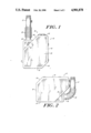
- FIG. 1 is a side view of a container according to the invention showing the nozzle extending directly outwardly therefrom in its normal open unflexed state;
- FIG. 2 is a side view of a container according to the invention shown in the nozzle interlocked in its storage position adjacent the front end wall;
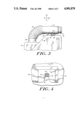
- FIG. 3 is a close-up side view of the nozzle and interference lock mechanism engaged so as to hold the nozzle in its storage position;
- FIG. 4 is a close-up, front end, cross sectional view showing the male component(s) of the interference lock mechanism engaged within the female component of the nozzle's interlocking mechanism;
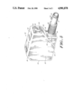
- FIG. 5 is a side isometric view of a container according to the invention showing the stepped nature of the front end wall of the container;
- FIGS. 6 and 6a are respectively top and side elevational view of prior art utilizing a locking mechanism.
- FIGS. 1, 2 and 5 There is shown in FIGS. 1, 2 and 5 a container 10, the body of which comprises a rigid hollow box having opposing bottom 14 and top 16 end walls, opposing rear 18 and front 20 end walls, and opposing side 22 walls.
- the walls of the container 10 are connected at rounded corners and edges.
- the front end wall 20 comprises an outset wall segment 24, an inset wall segment 26 and a slanted intermediate wall segment 28 which forms a continuous wall section connecting front wall segments 24, 26.
- the width of the inset front wall segment 26 from side to side is typically slightly less than the width from side to side between side walls 22 such that a pair of reinforcing ribs 30 are formed along the sides of the inset segment 26.
- Ribs 30 extend at an angle from the top 32 of wall segment 26 downward to bottom wall 14. At the top 32 of wall segment 26, the ribs 30 merge into and form the side edges of intermediate wall section 28, FIGS. 1, 3, 5.
- Top end wall 16 and rear end wall 18 are connected by a slanted rear wall section 34.
- top 16 and rear 18 end walls and bottom 14 and front 20 end walls are disposed in substantially perpendicular relationship to each other thus collectively forming a substantially rectangular hollow body having a stepped front end 20 and a slanted upper rear end 34.
- the merging of ribs 30 with the side edges of wall section 28 form a continuous rib extending from the bottom edge of wall section 24 to bottom end wall 14 and, the angle of such continuous rib is preferably selected to be substantially parallel to the angle of slant of the top rear end wall section 34 which connects top 16 and rear 18 end walls.
- Nozzle 12 is integrally formed and protrudes from the outer face of inset wall segment 26. As shown in FIG. 5, the nozzle 12 is in its normal unstressed position and by virtue of its integral formation in the wall segment 26 protrudes horizontally in its normal unstressed state such that the axis of the nozzle 12 is substantially parallel to bottom end wall 14. As shown, the stem 36 of nozzle 12 is located adjacent to and protrudes from the intersection of bottom wall 14 and front wall 20 which is opposite the upper rear slanted wall segment 34. Such opposite upper and lower end corner disposition of slanted wall section 34 and nozzle 12 render wall section 34 ideally useful as a hand grip for pouring fluids stored in container 10 through nozzle 12, FIGS. 1, 2, 5.
- Nozzle 12 and the body of container 10 are preferably molded from a rigid flexibly resilient plastic material.
- the rigid resilience of the plastic material and the integral formation of the stem 36 of nozzle 12 in wall segment 36 impart a resilient bendability to nozzle 12 whereby the entire length of nozzle 12 may be bent about stem 36 by application of force against the axis of the nozzle 12.
- nozzle 12 is provided with a pleated elbow section 38 adapted to enable the bending of nozzle 12 along its axis both to a storage position adjacent wall segment 24 as shown in FIGS. 2, 3 and to other pouring positions.
- the distal end of nozzle 12 is provided with a delta-shaped male interlocking component 40 and the face of outset wall segment 24 is formed with a female interlocking component 42.
- male 40 and female 42 components comprise an interference lock mechanism.
- the male component 40 is delta-shaped with flared ends or detents 44 spaced from nozzle 12. These ends engage undercut portions 46 in the complementary female component 42.
- the male component 40 is integrally formed at such a point along the nozzle 12 as to require the nozzle 12 to be bent not only about elbow 38 but also about stem 36 in order to position the detents 44 within the aperture 50.
- the stem 36 exerts a resilient force on nozzle 12 in the -X direction (as viewed in the X-Y diagram forming part of FIG. 3.) in addition to an upwardly resilient force in the +Y direction which is exerted as result of the bending about pleated elbow 38. If the nozzle 12 were bent about elbow 38 at a true 90 degree angle, the male component 40 could not be positioned within complementary aperture 50.
- component 40 on the nozzle 12 thus acts to require that the nozzle 12 be bent about the stem 36 in order to position component 40 and detents 44 within aperture 50.
- Such requirement of further bending of the nozzle 12 about stem 36 in order to lock the nozzle 12 in the storage position as shown in FIGS. 2, 3 thus creates a backward frictional tension between the outside surfaces of detents 44 and the undercut 46, in addition to the interference tension which is created between the same surfaces by bending around elbow 38 and the resultant resistance force in the +Y direction which results from such elbow 38 bending.
- aperture 50 is tapered from a flared opening toward a closed end with the taper sufficient to permit easy initial insertion and increasing friction engagement on further insertion of the component 40.
- a resilient resistance of stem 36 to bending around its axis and a resilient resistance of elbow 38 to bending about its axis collectively also serve to create an interlocking interference frictional force between the upper surfaces of detents 44 and lower surfaces of aperture 46 such that nozzle 12 is effectively locked into the storage position shown in FIGS. 2, 3 until the component 40 of nozzle 12 is intentionally released from aperture 50.
Landscapes
- Engineering & Computer Science (AREA)
- Mechanical Engineering (AREA)
- Ceramic Engineering (AREA)
- Containers And Packaging Bodies Having A Special Means To Remove Contents (AREA)
Abstract
Description
Claims (21)
Priority Applications (1)
| Application Number | Priority Date | Filing Date | Title |
|---|---|---|---|
| US07/239,699 US4901878A (en) | 1987-03-16 | 1988-09-02 | Rigid fluid container |
Applications Claiming Priority (2)
| Application Number | Priority Date | Filing Date | Title |
|---|---|---|---|
| US2602487A | 1987-03-16 | 1987-03-16 | |
| US07/239,699 US4901878A (en) | 1987-03-16 | 1988-09-02 | Rigid fluid container |
Related Parent Applications (1)
| Application Number | Title | Priority Date | Filing Date |
|---|---|---|---|
| US2602487A Continuation-In-Part | 1987-03-16 | 1987-03-16 |
Publications (1)
| Publication Number | Publication Date |
|---|---|
| US4901878A true US4901878A (en) | 1990-02-20 |
Family
ID=26700617
Family Applications (1)
| Application Number | Title | Priority Date | Filing Date |
|---|---|---|---|
| US07/239,699 Expired - Fee Related US4901878A (en) | 1987-03-16 | 1988-09-02 | Rigid fluid container |
Country Status (1)
| Country | Link |
|---|---|
| US (1) | US4901878A (en) |
Cited By (43)
| Publication number | Priority date | Publication date | Assignee | Title |
|---|---|---|---|---|
| US5161266A (en) * | 1991-08-06 | 1992-11-10 | Hildebrand Gerald R | Portable shower |
| US5171538A (en) * | 1989-11-21 | 1992-12-15 | Boehringer Mannheim Gmbh | Reagent supply system for a medical analytical instrument |
| US5226574A (en) * | 1991-08-16 | 1993-07-13 | Durinzi Jr Armando F | Portable dispensing container for liquid fuel |
| US5244021A (en) * | 1991-12-13 | 1993-09-14 | Hau Ernest F | Fuel transfer container |
| USD340866S (en) | 1990-08-14 | 1993-11-02 | Lykes Pasco Packing Company | Combined bottle and cap |
| US5353952A (en) * | 1993-06-25 | 1994-10-11 | Donche Mark L | One-handed party and utility plate |
| USD355854S (en) | 1993-05-03 | 1995-02-28 | Baron Richard D | Container |
| US5469993A (en) * | 1993-12-02 | 1995-11-28 | Monsanto Company | Dispensing system |
| USD375048S (en) | 1995-05-18 | 1996-10-29 | The Coca-Cola Company | Collapsible bottle |
| USD376540S (en) | 1995-10-18 | 1996-12-17 | Boumil John J | Leakless gas can |
| USD380148S (en) * | 1995-07-19 | 1997-06-24 | Monsanto Company Of St. Louis | Dispensing system |
| US5667101A (en) * | 1995-05-19 | 1997-09-16 | The Coca-Cola Company | Collapsible bottle |
| US5810211A (en) * | 1997-03-06 | 1998-09-22 | Hayes Products, Llc | Pump assembly with sliding plug |
| US5816447A (en) * | 1997-03-06 | 1998-10-06 | Hayes Products, Llc | Non-aerosol pump spray apparatus |
| USD402205S (en) | 1997-08-27 | 1998-12-08 | Hayes Products, Llc | Bottle |
| USD407312S (en) | 1997-08-28 | 1999-03-30 | Hayes Products, Llc | Sprayer |
| US5918782A (en) * | 1997-03-06 | 1999-07-06 | Hayes Products, Llc | Pump assembly with sprayer |
| US5975380A (en) * | 1998-03-02 | 1999-11-02 | West, Jr.; Roy A. | Container including an accordion like pouring spout |
| USD417618S (en) * | 1997-08-28 | 1999-12-14 | Hayes Products, Llc | Pump assembly |
| USD418201S (en) * | 1997-08-27 | 1999-12-28 | Hayes Products, Llc | Bottle, pump and sprayer assembly |
| US6089414A (en) * | 1997-03-06 | 2000-07-18 | Hayes Products, Llc | Pump assembly with one piece piston |
| US6360922B1 (en) | 1999-04-27 | 2002-03-26 | Hayes Products, Llc | Pump assembly with pressure release capability |
| USD467806S1 (en) | 1990-08-14 | 2002-12-31 | Vitality Foodservice, Inc. | Container |
| US20040007600A1 (en) * | 2002-04-02 | 2004-01-15 | Englhard Ronald F. | Pump assembly with continuous tube |
| US20040104194A1 (en) * | 2002-12-02 | 2004-06-03 | Dennison Robert A. | Bottle of sprayable liquid with flexible neck |
| US20050139618A1 (en) * | 2003-10-20 | 2005-06-30 | Shanklin Donald J. | Hand held pressurized sprayer |
| US20050178776A1 (en) * | 2003-11-10 | 2005-08-18 | Wilson Craig N. | Beverage container with rigid inner contaner |
| USD529750S1 (en) | 2004-09-15 | 2006-10-10 | Vitality Food Service Inc. | Dispenser |
| USD548094S1 (en) * | 2005-06-21 | 2007-08-07 | Salas Arthur C | Container with accordion spout |
| USD591394S1 (en) | 2009-01-30 | 2009-04-28 | James Ugone | Watering can comprising a rose docking station, glove mounts, fertilizer containment chamber, measuring spoon and measuring tube |
| US20090272760A1 (en) * | 2008-05-05 | 2009-11-05 | James Ugone | Fluid Containing and Dispersing Apparatus |
| USD605519S1 (en) * | 2008-06-19 | 2009-12-08 | Jayd Caggiano | Spray bottle |
| US20100163641A1 (en) * | 2008-12-27 | 2010-07-01 | James Ugone | Fluid Containing and Dispersing Apparatus |
| US7784205B1 (en) | 2005-08-29 | 2010-08-31 | Nestec S.A. | Display for dispensing maching |
| US7913878B1 (en) | 2005-08-29 | 2011-03-29 | Nestec, S. A. | Terminal orifice processor |
| USD762120S1 (en) * | 2015-03-11 | 2016-07-26 | Michael Valentine | Oil can |
| USD762477S1 (en) * | 2015-03-11 | 2016-08-02 | Michael Valentine | Oil can |
| US20170369204A1 (en) * | 2014-12-10 | 2017-12-28 | Dbh Enterprises, Inc. | Gravity assisted portable fuel container |
| US20190314841A1 (en) * | 2016-12-06 | 2019-10-17 | Taplast Spa | Dispensing device for dispensing liquids or fluids |
| USD929864S1 (en) * | 2020-08-21 | 2021-09-07 | Steen Products, Inc. | Container |
| WO2022015346A1 (en) * | 2020-07-17 | 2022-01-20 | Steen Products, Inc. | Container |
| US11530125B2 (en) | 2020-07-17 | 2022-12-20 | Steen Products, Inc. | Container |
| US20240359881A1 (en) * | 2023-04-28 | 2024-10-31 | TLK Diversified Investments, LLC | One-piece cap, spout, and air vent |
Citations (6)
| Publication number | Priority date | Publication date | Assignee | Title |
|---|---|---|---|---|
| US1838468A (en) * | 1927-08-03 | 1931-12-29 | Thomson Volney Wayne | Liquid dispensing can |
| US3583590A (en) * | 1969-09-12 | 1971-06-08 | Colgate Palmolive Co | Container |
| US4199140A (en) * | 1977-08-22 | 1980-04-22 | Bruno Ferretti | Portable weight lift and force resistive exerciser |
| US4236655A (en) * | 1978-09-05 | 1980-12-02 | S.A.Y. Industries, Inc. | Container with flexible nozzle |
| US4243162A (en) * | 1979-08-15 | 1981-01-06 | Illinois Tool Works Inc. | Vessel structure |
| US4351454A (en) * | 1980-07-16 | 1982-09-28 | Maynard Jr Walter P | Liquid container having stacking feature |
-
1988
- 1988-09-02 US US07/239,699 patent/US4901878A/en not_active Expired - Fee Related
Patent Citations (6)
| Publication number | Priority date | Publication date | Assignee | Title |
|---|---|---|---|---|
| US1838468A (en) * | 1927-08-03 | 1931-12-29 | Thomson Volney Wayne | Liquid dispensing can |
| US3583590A (en) * | 1969-09-12 | 1971-06-08 | Colgate Palmolive Co | Container |
| US4199140A (en) * | 1977-08-22 | 1980-04-22 | Bruno Ferretti | Portable weight lift and force resistive exerciser |
| US4236655A (en) * | 1978-09-05 | 1980-12-02 | S.A.Y. Industries, Inc. | Container with flexible nozzle |
| US4243162A (en) * | 1979-08-15 | 1981-01-06 | Illinois Tool Works Inc. | Vessel structure |
| US4351454A (en) * | 1980-07-16 | 1982-09-28 | Maynard Jr Walter P | Liquid container having stacking feature |
Cited By (57)
| Publication number | Priority date | Publication date | Assignee | Title |
|---|---|---|---|---|
| US5171538A (en) * | 1989-11-21 | 1992-12-15 | Boehringer Mannheim Gmbh | Reagent supply system for a medical analytical instrument |
| USD467806S1 (en) | 1990-08-14 | 2002-12-31 | Vitality Foodservice, Inc. | Container |
| USD340866S (en) | 1990-08-14 | 1993-11-02 | Lykes Pasco Packing Company | Combined bottle and cap |
| US5161266A (en) * | 1991-08-06 | 1992-11-10 | Hildebrand Gerald R | Portable shower |
| US5226574A (en) * | 1991-08-16 | 1993-07-13 | Durinzi Jr Armando F | Portable dispensing container for liquid fuel |
| US5244021A (en) * | 1991-12-13 | 1993-09-14 | Hau Ernest F | Fuel transfer container |
| USD355854S (en) | 1993-05-03 | 1995-02-28 | Baron Richard D | Container |
| US5353952A (en) * | 1993-06-25 | 1994-10-11 | Donche Mark L | One-handed party and utility plate |
| US5469993A (en) * | 1993-12-02 | 1995-11-28 | Monsanto Company | Dispensing system |
| USD375048S (en) | 1995-05-18 | 1996-10-29 | The Coca-Cola Company | Collapsible bottle |
| US5667101A (en) * | 1995-05-19 | 1997-09-16 | The Coca-Cola Company | Collapsible bottle |
| USD380148S (en) * | 1995-07-19 | 1997-06-24 | Monsanto Company Of St. Louis | Dispensing system |
| USD376540S (en) | 1995-10-18 | 1996-12-17 | Boumil John J | Leakless gas can |
| US6467657B2 (en) | 1997-03-06 | 2002-10-22 | Donald J. Shanklin | Pump assembly with one piece piston |
| US5810211A (en) * | 1997-03-06 | 1998-09-22 | Hayes Products, Llc | Pump assembly with sliding plug |
| US5860574A (en) * | 1997-03-06 | 1999-01-19 | Hayes Products, Llc | Pump assembly with bayonet lock |
| US5918782A (en) * | 1997-03-06 | 1999-07-06 | Hayes Products, Llc | Pump assembly with sprayer |
| US6089414A (en) * | 1997-03-06 | 2000-07-18 | Hayes Products, Llc | Pump assembly with one piece piston |
| US6296154B1 (en) | 1997-03-06 | 2001-10-02 | Hayes Products, Llc | Pump assembly with one piece piston |
| US7198178B2 (en) | 1997-03-06 | 2007-04-03 | Shanklin Donald J | Pump assembly with piston |
| US20050023305A1 (en) * | 1997-03-06 | 2005-02-03 | Shanklin Donald J. | Pump assembly with one piece piston |
| US5816447A (en) * | 1997-03-06 | 1998-10-06 | Hayes Products, Llc | Non-aerosol pump spray apparatus |
| USD402205S (en) | 1997-08-27 | 1998-12-08 | Hayes Products, Llc | Bottle |
| USD418201S (en) * | 1997-08-27 | 1999-12-28 | Hayes Products, Llc | Bottle, pump and sprayer assembly |
| USD407312S (en) | 1997-08-28 | 1999-03-30 | Hayes Products, Llc | Sprayer |
| USD417618S (en) * | 1997-08-28 | 1999-12-14 | Hayes Products, Llc | Pump assembly |
| US5975380A (en) * | 1998-03-02 | 1999-11-02 | West, Jr.; Roy A. | Container including an accordion like pouring spout |
| US6360922B1 (en) | 1999-04-27 | 2002-03-26 | Hayes Products, Llc | Pump assembly with pressure release capability |
| US20040007600A1 (en) * | 2002-04-02 | 2004-01-15 | Englhard Ronald F. | Pump assembly with continuous tube |
| US20060060613A1 (en) * | 2002-04-02 | 2006-03-23 | Englhard Ronald F | Pump assembly with continuous tube |
| US7789275B2 (en) | 2002-04-02 | 2010-09-07 | Meadwestvaco Calmar, Inc. | Pump assembly with continuous tube |
| US6953133B2 (en) | 2002-04-02 | 2005-10-11 | Hayes Products, Inc. | Pump assembly with continuous tube |
| US20040104194A1 (en) * | 2002-12-02 | 2004-06-03 | Dennison Robert A. | Bottle of sprayable liquid with flexible neck |
| US20050139618A1 (en) * | 2003-10-20 | 2005-06-30 | Shanklin Donald J. | Hand held pressurized sprayer |
| US7427004B2 (en) | 2003-10-20 | 2008-09-23 | Meadwestvaco Calmar, Inc. | Hand held pressurized sprayer |
| US20050178776A1 (en) * | 2003-11-10 | 2005-08-18 | Wilson Craig N. | Beverage container with rigid inner contaner |
| WO2005047169A3 (en) * | 2003-11-10 | 2006-03-09 | First Austin Funding Corp | Beverage container with rigid inner container |
| USD529750S1 (en) | 2004-09-15 | 2006-10-10 | Vitality Food Service Inc. | Dispenser |
| USD548094S1 (en) * | 2005-06-21 | 2007-08-07 | Salas Arthur C | Container with accordion spout |
| US7913878B1 (en) | 2005-08-29 | 2011-03-29 | Nestec, S. A. | Terminal orifice processor |
| US7784205B1 (en) | 2005-08-29 | 2010-08-31 | Nestec S.A. | Display for dispensing maching |
| US20090272760A1 (en) * | 2008-05-05 | 2009-11-05 | James Ugone | Fluid Containing and Dispersing Apparatus |
| USD605519S1 (en) * | 2008-06-19 | 2009-12-08 | Jayd Caggiano | Spray bottle |
| US8292122B2 (en) | 2008-12-27 | 2012-10-23 | The U-CAN Brand, LLC | Fluid containing and dispersing apparatus |
| US20100163641A1 (en) * | 2008-12-27 | 2010-07-01 | James Ugone | Fluid Containing and Dispersing Apparatus |
| USD591394S1 (en) | 2009-01-30 | 2009-04-28 | James Ugone | Watering can comprising a rose docking station, glove mounts, fertilizer containment chamber, measuring spoon and measuring tube |
| US20170369204A1 (en) * | 2014-12-10 | 2017-12-28 | Dbh Enterprises, Inc. | Gravity assisted portable fuel container |
| USD762120S1 (en) * | 2015-03-11 | 2016-07-26 | Michael Valentine | Oil can |
| USD762477S1 (en) * | 2015-03-11 | 2016-08-02 | Michael Valentine | Oil can |
| US10751741B2 (en) * | 2016-12-06 | 2020-08-25 | Taplast S.P.A. | Dispensing device for dispensing liquids or fluids |
| US20190314841A1 (en) * | 2016-12-06 | 2019-10-17 | Taplast Spa | Dispensing device for dispensing liquids or fluids |
| WO2022015346A1 (en) * | 2020-07-17 | 2022-01-20 | Steen Products, Inc. | Container |
| US11530125B2 (en) | 2020-07-17 | 2022-12-20 | Steen Products, Inc. | Container |
| US11530073B2 (en) | 2020-07-17 | 2022-12-20 | Steen Products, Inc. | Container |
| USD929864S1 (en) * | 2020-08-21 | 2021-09-07 | Steen Products, Inc. | Container |
| US20240359881A1 (en) * | 2023-04-28 | 2024-10-31 | TLK Diversified Investments, LLC | One-piece cap, spout, and air vent |
| US12404080B2 (en) * | 2023-04-28 | 2025-09-02 | TLK Diversified Investments, LLC | One-piece cap, spout, and air vent |
Similar Documents
| Publication | Publication Date | Title |
|---|---|---|
| US4901878A (en) | Rigid fluid container | |
| US4629153A (en) | Container holder device | |
| US7175498B2 (en) | Combination toy building block and container for holding liquids and the like | |
| US20090065469A1 (en) | Bottle Handling Device | |
| US4951903A (en) | Bag holder | |
| US4723679A (en) | Tray or tote box collar extension | |
| US6237802B1 (en) | Angled-cut paint brush holder | |
| US4860982A (en) | Container support | |
| US4310109A (en) | Pencil holder | |
| US4516687A (en) | Handle for a vessel | |
| US10625285B2 (en) | Container for nested sprayer handle | |
| US12070143B2 (en) | Apparatus for drinking | |
| CA2004921A1 (en) | Rigid fluid container | |
| US4339102A (en) | Readily separable jar mounting device | |
| GB2089207A (en) | Improvements in or relating to a support for a picture frame | |
| JPS63232146A (en) | Vessel for fluid | |
| JPS6140668Y2 (en) | ||
| EP0155777A1 (en) | Carrying handle and article having such a handle | |
| JPH0634281Y2 (en) | Container with handle | |
| JPS6315157Y2 (en) | ||
| JPH0350027Y2 (en) | ||
| JPH0538376Y2 (en) | ||
| JPH0226005U (en) | ||
| JPH0130369Y2 (en) | ||
| JPH0126594Y2 (en) |
Legal Events
| Date | Code | Title | Description |
|---|---|---|---|
| AS | Assignment |
Owner name: S.A.Y. INDUSTRIES, INC., 163 PIONEER DRIVE, LEOMIN Free format text: ASSIGNMENT OF ASSIGNORS INTEREST.;ASSIGNOR:HUMPHRIES, ROMILLY H.;REEL/FRAME:004982/0089 Effective date: 19881017 Owner name: S.A.Y. INDUSTRIES, INC., A MASSACHUSETTS CORP., MA Free format text: ASSIGNMENT OF ASSIGNORS INTEREST;ASSIGNOR:HUMPHRIES, ROMILLY H.;REEL/FRAME:004982/0089 Effective date: 19881017 |
|
| FEPP | Fee payment procedure |
Free format text: PAYOR NUMBER ASSIGNED (ORIGINAL EVENT CODE: ASPN); ENTITY STATUS OF PATENT OWNER: LARGE ENTITY |
|
| AS | Assignment |
Owner name: UNIVERSITY BANK, N.A., A MA BANK AND TRUST CO., MA Free format text: SECURITY INTEREST;ASSIGNOR:SCRIBE SYSTEMS, INC.;REEL/FRAME:005330/0909 Effective date: 19900531 |
|
| AS | Assignment |
Owner name: YOUNG, STANLEY A., 163 PIONEER DRIVE, LEOMINSTER, Free format text: SECURITY INTEREST;ASSIGNOR:UNIVERSITY BANK, N.A., A NATIONAL BANKING ASSOCIATION;REEL/FRAME:005568/0155 Effective date: 19901228 |
|
| AS | Assignment |
Owner name: E.T. PACKAGING, INC., 163 PIONEER DRIVE, LEOMINSTE Free format text: ASSIGNMENT OF ASSIGNORS INTEREST.;ASSIGNOR:YOUNG, STANLEY A.;REEL/FRAME:005620/0486 Effective date: 19910226 |
|
| FEPP | Fee payment procedure |
Free format text: PAT HLDR NO LONGER CLAIMS SMALL ENT STAT AS SMALL BUSINESS (ORIGINAL EVENT CODE: LSM2); ENTITY STATUS OF PATENT OWNER: LARGE ENTITY |
|
| FPAY | Fee payment |
Year of fee payment: 4 |
|
| REMI | Maintenance fee reminder mailed | ||
| LAPS | Lapse for failure to pay maintenance fees | ||
| FP | Lapsed due to failure to pay maintenance fee |
Effective date: 19980225 |
|
| STCH | Information on status: patent discontinuation |
Free format text: PATENT EXPIRED DUE TO NONPAYMENT OF MAINTENANCE FEES UNDER 37 CFR 1.362 |