US4901828A - Method and apparatus for controlling displacement of a piston in a shock absorber - Google Patents
Method and apparatus for controlling displacement of a piston in a shock absorber Download PDFInfo
- Publication number
- US4901828A US4901828A US07/361,720 US36172089A US4901828A US 4901828 A US4901828 A US 4901828A US 36172089 A US36172089 A US 36172089A US 4901828 A US4901828 A US 4901828A
- Authority
- US
- United States
- Prior art keywords
- annular collar
- pressure cylinder
- piston
- flow
- split ring
- Prior art date
- Legal status (The legal status is an assumption and is not a legal conclusion. Google has not performed a legal analysis and makes no representation as to the accuracy of the status listed.)
- Expired - Lifetime
Links
Images
Classifications
-
- F—MECHANICAL ENGINEERING; LIGHTING; HEATING; WEAPONS; BLASTING
- F16—ENGINEERING ELEMENTS AND UNITS; GENERAL MEASURES FOR PRODUCING AND MAINTAINING EFFECTIVE FUNCTIONING OF MACHINES OR INSTALLATIONS; THERMAL INSULATION IN GENERAL
- F16F—SPRINGS; SHOCK-ABSORBERS; MEANS FOR DAMPING VIBRATION
- F16F9/00—Springs, vibration-dampers, shock-absorbers, or similarly-constructed movement-dampers using a fluid or the equivalent as damping medium
- F16F9/32—Details
- F16F9/48—Arrangements for providing different damping effects at different parts of the stroke
- F16F9/49—Stops limiting fluid passage, e.g. hydraulic stops or elastomeric elements inside the cylinder which contribute to changes in fluid damping
-
- F—MECHANICAL ENGINEERING; LIGHTING; HEATING; WEAPONS; BLASTING
- F16—ENGINEERING ELEMENTS AND UNITS; GENERAL MEASURES FOR PRODUCING AND MAINTAINING EFFECTIVE FUNCTIONING OF MACHINES OR INSTALLATIONS; THERMAL INSULATION IN GENERAL
- F16F—SPRINGS; SHOCK-ABSORBERS; MEANS FOR DAMPING VIBRATION
- F16F9/00—Springs, vibration-dampers, shock-absorbers, or similarly-constructed movement-dampers using a fluid or the equivalent as damping medium
- F16F9/32—Details
- F16F9/48—Arrangements for providing different damping effects at different parts of the stroke
Definitions
- This invention relates to automotive suspension systems, and more particularly to a method and apparatus for controlling the displacement of a piston in a shock absorber.
- shock absorbers are used in connection with automotive suspension systems to absorb unwanted vibrations which occur during driving. To absorb this unwanted vibration, shock absorbers are generally connected between the body and the suspension of the automobile. A piston is located within the shock absorber and is connected to the body of the automobile through a piston rod. Because the piston is able to limit the flow of damping fluid within the working chamber of the shock absorber when the shock absorber is compressed or extended, the shock absorber is able to produce a damping force which counteracts the vibration which would otherwise be transmitted from the suspension of the automobile to the body.
- a further object of the present invention is to provide a method and apparatus for controlling the displacement of a piston in which the damping forces opposing excessive displacement of the piston increases with increasing piston displacement.
- Another object of the present invention is to provide a method and apparatus for controlling the displacement of a piston in which the potential for damage to the piston due to excessive displacement of the piston is reduced.
- a further object of the present invention is to provide a method and apparatus for controlling the displacement of a piston in which ride discomfort caused by the impact between the piston and the rod guide is reduced.
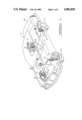
- FIG. 1 is an illustration of an automobile using the method and apparatus for controlling displacement of a piston according to the teachings of the preferred embodiments of the present invention
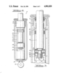
- FIG. 2 is a reduced side elevational view, partially broken away, of a shock absorber using the apparatus for controlling displacement of a piston according to the teachings of the preferred embodiments of the present invention
- FIG. 3 is an enlarged elevational view of a shock absorber using the apparatus for controlling displacement of a piston shown in FIG. 2 according to the first preferred embodiment of the present invention
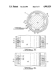
- FIG. 4 is a view of the apparatus for controlling displacement of a piston according to the first preferred embodiment of the present invention taken in the direction of line 4--4 in FIG. 3;
- FIG. 5 is a side elevational view of the apparatus for controlling displacement of a piston according to the first preferred embodiment of the present invention taken in the direction of line 5--5 of FIG. 4 when the apparatus is at the upper portion of the pressure chamber;
- FIG. 6 is a side elevational view of the apparatus for controlling displacement of a piston according to the first preferred embodiment shown in FIG. 5 when the apparatus is near the lower portion of the pressure chamber;
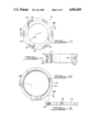
- FIG. 7 is a top view of the split ring shown in FIG. 6;
- FIG. 8 is a side elevational view of the split ring taken in the direction of line 8--8 in FIG. 7;
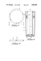
- FIG. 9 is an enlarged elevational view of a shock absorber using the apparatus for controlling displacement of a piston according to the second preferred embodiment of the present invention.
- FIG. 10 is a view of the apparatus for controlling displacement of a piston shown in FIG. 9;
- FIG. 11 is a side elevational view of the collar shown in FIG. 10 taken in the direction of line 11--11;
- FIG. 12 is a top view of the split ring shown in FIG. 9.
- FIG. 13 is a side elevational view of the split ring shown in FIG. 12 taken in the direction of line 13--13.
- the shock absorbers 10 are depicted in operative association with a diagrammatic representation of a conventional automobile 12.
- the automobile 12 includes a rear suspension 14 having a transversely extending rear axle association (not shown) adapted to operatively support the vehicle's rear wheels 16.
- the rear axle assembly is operatively connected to the automobile 12 by means of a pair of shock absorbers 10 as well as the helical coil springs 18.
- the automobile 12 has a front suspension system 20 including a transversely extending front axle assembly (not shown) to operatively support the front wheels 22.
- the front axle assembly is operatively connected to the automobile 12 by means of a second pair of shock absorbers 10 and by the helical coil springs 24.
- the shock absorbers 10 serve to dampen the relative movement of the unsprung portion (i.e., the front and rear suspensions 14 and 20) and the spring portion (i.e., the body 26) of the automobile 12. While the automobile 12 has been depicted as a passenger car, the shock absorber 10 may be used with other types of automotive vehicles, snowmobiles, airplanes and damping devices in general as well. Further, the term "shock absorber" as used herein will refer to shock absorbers in the general sense of the phrase and will include MacPherson struts.
- the shock absorber 10 comprises an elongated pressure tube cylinder 30 defining a damping fluid-containing working chamber 32.
- the pressure cylinder 30 has a straight cylindrical portion 34 and an axially extending and inwardly tapered portion 36.
- Disposed within the working chamber 32 is a reciprocal piston 38.
- the reciprocal piston 38 is secured to one end of an axially extending piston post 40 which is is in turn secured to an axially extending piston rod 42.
- the piston 38 comprises a housing 44 having a plurality of ridges 46 disposed on the annular exterior of the piston housing 44.
- the ridges 46 are used to secure an annular teflon sleeve 48 which is disposed between the ridges 46 of the piston housing 44 and the pressure cylinder 30.
- the teflon sleeve 48 permits movement of the piston 38 with respect to the pressure cylinder 30 without generating undue frictional forces.
- the piston 38 further includes a valve disk 62 which provides means for controlling the flow of damping fluid between said first and second portions of said working chamber 32. It is to be understood that the piston 38 was described in general terms as the present invention may be used with a wide variety of pistons. One such piston is disclosed in U.S. Pat. No. 4,113,072, which is hereby incorporated by reference.
- the shock absorber 10 further comprises a base valve (not shown) located within the lower end of the pressure cylinder 30 and is used to control the flow of damping fluid between the working chamber 32 and an annular fluid reservoir 64.
- the annular fluid reservoir 64 is defined as the space between the outer periphery of the cylinder 30 and the inner periphery of a reservoir tube or cylinder 66 which is arranged essentially around the exterior of the pressure cylinder 30.
- the construction in operation of the base valve may be of the type shown and described in U.S. Pat. No. 3,771,626, which is hereby incorporated by reference.
- the lower end of the shock absorber 10 is provided with generally cup-shaped end cap 68, while the upper end of the shock absorber 10 includes a generally cup-shaped end cap 70.
- a suitable end fitting 72 is secured to the lower end of the lower cap 68 for operatively securing the shock absorber 10 between the body and axle assembly of the automobile 12 in a conventional manner.
- the upper portion (not shown) of the piston rod 42 is attached to the automobile 12 in a conventional manner.
- a rod guide 74 is disposed at the upper end of the cylinder 30 within the upper end cap 70. The rod guide 74 is used to allow the piston rod 42 to be displaced in a substantially axial direction within the pressure cylinder 30.
- the apparatus 76 for controlling displacement of the piston 38 comprises an annular collar 78 which is coaxially disposed on the piston rod 42.
- the annular collar 78 comprises a plurality of axially extending flow passages 80 which are disposed between the inner radial surface 82 of the annular collar 78 and the radially outer surface 84 of the annular collar 78.
- the flow passages 80 are defined in part by a radially inward surface 88 disposed between the radially inward surface 82 and the radially outward surface 84 of the annular collar 78, as well as the radially outward surface 90 of the flow passages 80 which is also disposed between the radially inward surface 82 and the radially outward surface 84 of the annular collar 78.
- the flow passages 80 permit damping fluid to flow between the region of the working chamber 32 above the annular collar 78 and the portion of the working chamber 32 between the annular collar 78 and the piston 38.
- the annular collar 78 further comprises a groove 92.
- the groove 92 extending circumferentially around the radially outward surface of the annular collar 78. Further, the groove 92 extends through the radially outward surface 90 of the flow passages 80 as well as through the radially inward surface 88 of the flow passages 80 so as to form a circumferential ring seat 94.
- the apparatus 76 further comprises a split ring 96.
- the split ring 96 is operable to be inserted into the groove 92 and contains end portions 98 which are separated by a gap.
- the split ring 96 extends radially from the groove 92 to the cylinder 30 to such an extent that the ring 96 does not obstruct the flow of damping fluid through the flow passages 80 as shown in FIG. 6.
- the apparatus 176 for controlling displacement of the piston 138 comprises an annular collar 178 which is coaxially disposed on the piston rod 142.
- the annular collar 178 comprises a plurality of axially extending flow passages 180 which are disposed between the inner radial surface 182 of the annular collar 178 and the radially outer surface 184 of the annular collar 178.
- the flow passages 180 are defined in part by a radially inward surface 188 disposed between the radially inward surface 182 and the radially outward surface 184 of the annular collar 178, as well as the radially outward surface 190 of the flow passages 180 which is also disposed between the radially inward surface 182 and the radially outward surface 184 of the annular collar 178.
- the flow passages 180 permit damping fluid to flow between the region of the working chamber 132 above the annular collar 178 and the portion of the working chamber 132 between the annular collar 178 and the piston 138.
- the annular collar 178 further comprises a groove 192.
- the groove 192 extending circumferentially around the radially outward surface of the annular collar 178. Further, the groove 192 extends through the radially outward surface 190 of the flow passages 180 as well as through the radially inward surface 188 of the flow passages 180 so as to form a circumferential ring seat 194.
- the groove 192 mates with an enlarged region 193 of the flow passage 180 so as to allow for minor misalignment of the flow passages 180 with the annular flow passage described below of the split ring 196.
- the apparatus further comprises a split ring 196.
- the split ring 196 is operable to be inserted into the groove 192 and contains end portions 198 which are separated by a gap.
- the split ring 196 includes annular flow passage 200 which is operable to fluidly communicate with the flow passages 180 in the annular collar 178 when the split ring 196 is seated within the circumferential ring seat 194.
- the split ring 196 cooperates with an outwardly tapered portion 136 of the cylinder 130, which is disposed between a large diameter portion 204 of the cylinder 130 as well as a small diameter portion 208 of the cylinder 130.
- the split ring 196 When the annular collar 178 is disposed approximate to the portion 208 of the cylinder 130, the split ring 196 is seated in the circumferential ring seat 194 so that the flow passage 200 in the split ring 196 fluidly communicates with the flow passages 180 in the annular collar 178. Accordingly, the apparatus 176 does not restrict movement of the piston 130.
Landscapes
- Engineering & Computer Science (AREA)
- General Engineering & Computer Science (AREA)
- Mechanical Engineering (AREA)
- Fluid-Damping Devices (AREA)
Abstract
Description
Claims (9)
Priority Applications (1)
| Application Number | Priority Date | Filing Date | Title |
|---|---|---|---|
| US07/361,720 US4901828A (en) | 1988-03-21 | 1989-05-31 | Method and apparatus for controlling displacement of a piston in a shock absorber |
Applications Claiming Priority (2)
| Application Number | Priority Date | Filing Date | Title |
|---|---|---|---|
| US17082188A | 1988-03-21 | 1988-03-21 | |
| US07/361,720 US4901828A (en) | 1988-03-21 | 1989-05-31 | Method and apparatus for controlling displacement of a piston in a shock absorber |
Publications (1)
| Publication Number | Publication Date |
|---|---|
| US4901828A true US4901828A (en) | 1990-02-20 |
Family
ID=26866461
Family Applications (1)
| Application Number | Title | Priority Date | Filing Date |
|---|---|---|---|
| US07/361,720 Expired - Lifetime US4901828A (en) | 1988-03-21 | 1989-05-31 | Method and apparatus for controlling displacement of a piston in a shock absorber |
Country Status (1)
| Country | Link |
|---|---|
| US (1) | US4901828A (en) |
Cited By (13)
| Publication number | Priority date | Publication date | Assignee | Title |
|---|---|---|---|---|
| US5350187A (en) * | 1992-10-16 | 1994-09-27 | Monroe Auto Equipment Company | Adjustable damping system |
| KR19990049122A (en) * | 1997-12-11 | 1999-07-05 | 오상수 | Shock Absorber |
| US6382372B1 (en) * | 2000-01-03 | 2002-05-07 | Tenneco Automotive Inc. | Ported disc variable bleed orifice |
| US6634471B2 (en) | 2001-02-05 | 2003-10-21 | Zf Sachs Ag | Hydraulic tension stop for vibration dampers |
| US6978711B1 (en) * | 1999-04-22 | 2005-12-27 | Van Der Blom Nicolaas | Combination of a chamber and a piston, a pump, a motor, a shock absorber and a transducer incorporating the combination |
| US20080006147A1 (en) * | 2002-05-24 | 2008-01-10 | Blom Nicolaas V D | Device comprising a combination of a chamber and a piston |
| US20100263975A1 (en) * | 2007-10-19 | 2010-10-21 | William Ernest Taylor Vallance | Improvements in Movement Controls |
| US20120061194A1 (en) * | 2010-09-07 | 2012-03-15 | Mando Corporation | Shock absorber |
| US20130139508A1 (en) * | 2010-06-15 | 2013-06-06 | Herakles | Triggered-stroke actuator provided with a gas discharge device |
| CN104879419A (en) * | 2014-02-28 | 2015-09-02 | 日立汽车系统株式会社 | Cylinder Apparatus |
| US20160153517A1 (en) * | 2013-07-25 | 2016-06-02 | KYB EUROPE HEADQUARTER, GmBH | System for controlling variable load in a hydraulic device |
| US20180195574A1 (en) * | 2015-06-30 | 2018-07-12 | Hitachi Automotive Systems, Ltd. | Cylinder device |
| US20210246961A1 (en) * | 2018-05-16 | 2021-08-12 | Hitachi Automotive Systems, Ltd. | Cylinder apparatus |
Citations (19)
| Publication number | Priority date | Publication date | Assignee | Title |
|---|---|---|---|---|
| US1137123A (en) * | 1914-05-19 | 1915-04-27 | Garibaldi De Fernanzo | Shock-absorber. |
| US1141696A (en) * | 1914-06-18 | 1915-06-01 | Garibaldi De Fernanzo | Draft-rigging. |
| GB191422044A (en) * | 1914-11-05 | 1915-06-17 | Electric & Ordnance Accessorie | Improvements relating to Dashpot Plungers. |
| US1143753A (en) * | 1914-06-08 | 1915-06-22 | Garibaldi De Fernanzo | Shock-absorber. |
| US1503881A (en) * | 1921-04-11 | 1924-08-05 | Ernest T Bros | Shock absorber |
| US1845167A (en) * | 1931-08-17 | 1932-02-16 | John A Mcgrew | Shock absorbing mechanism |
| US1920251A (en) * | 1931-08-28 | 1933-08-01 | Houde Eng Corp | Shock absorber |
| US2092259A (en) * | 1934-05-07 | 1937-09-07 | Gen Motors Corp | Shock absorber |
| GB653286A (en) * | 1948-08-26 | 1951-05-09 | Girling Ltd | Improvements in or relating to hydraulic shock absorbers |
| US2710077A (en) * | 1952-01-16 | 1955-06-07 | Vibratrol Inc | Hydraulic shock absorber |
| US3062331A (en) * | 1960-01-04 | 1962-11-06 | Ford Motor Co | Shock absorber |
| US3229589A (en) * | 1964-12-07 | 1966-01-18 | Signode Corp | Impact tool and pneumatic piston return system therefor |
| GB1194140A (en) * | 1967-10-03 | 1970-06-10 | Stabilus Ind Und Handels Ges M | Door-Closer. |
| GB1305311A (en) * | 1970-04-13 | 1973-01-31 | ||
| US3771626A (en) * | 1972-04-04 | 1973-11-13 | Monroe Auto Equipment Co | Pressurized shock absorber |
| US3835753A (en) * | 1972-09-19 | 1974-09-17 | A Bunyard | Air cylinder |
| US4048905A (en) * | 1976-03-29 | 1977-09-20 | The Boeing Company | Variable orifice hydraulic snubber |
| US4113072A (en) * | 1976-03-22 | 1978-09-12 | Monroe Auto Equipment Company | Piston valve assembly for a shock absorber |
| US4457498A (en) * | 1982-04-27 | 1984-07-03 | Pauliukonis Richard S | Force balanced die cylinders |
-
1989
- 1989-05-31 US US07/361,720 patent/US4901828A/en not_active Expired - Lifetime
Patent Citations (19)
| Publication number | Priority date | Publication date | Assignee | Title |
|---|---|---|---|---|
| US1137123A (en) * | 1914-05-19 | 1915-04-27 | Garibaldi De Fernanzo | Shock-absorber. |
| US1143753A (en) * | 1914-06-08 | 1915-06-22 | Garibaldi De Fernanzo | Shock-absorber. |
| US1141696A (en) * | 1914-06-18 | 1915-06-01 | Garibaldi De Fernanzo | Draft-rigging. |
| GB191422044A (en) * | 1914-11-05 | 1915-06-17 | Electric & Ordnance Accessorie | Improvements relating to Dashpot Plungers. |
| US1503881A (en) * | 1921-04-11 | 1924-08-05 | Ernest T Bros | Shock absorber |
| US1845167A (en) * | 1931-08-17 | 1932-02-16 | John A Mcgrew | Shock absorbing mechanism |
| US1920251A (en) * | 1931-08-28 | 1933-08-01 | Houde Eng Corp | Shock absorber |
| US2092259A (en) * | 1934-05-07 | 1937-09-07 | Gen Motors Corp | Shock absorber |
| GB653286A (en) * | 1948-08-26 | 1951-05-09 | Girling Ltd | Improvements in or relating to hydraulic shock absorbers |
| US2710077A (en) * | 1952-01-16 | 1955-06-07 | Vibratrol Inc | Hydraulic shock absorber |
| US3062331A (en) * | 1960-01-04 | 1962-11-06 | Ford Motor Co | Shock absorber |
| US3229589A (en) * | 1964-12-07 | 1966-01-18 | Signode Corp | Impact tool and pneumatic piston return system therefor |
| GB1194140A (en) * | 1967-10-03 | 1970-06-10 | Stabilus Ind Und Handels Ges M | Door-Closer. |
| GB1305311A (en) * | 1970-04-13 | 1973-01-31 | ||
| US3771626A (en) * | 1972-04-04 | 1973-11-13 | Monroe Auto Equipment Co | Pressurized shock absorber |
| US3835753A (en) * | 1972-09-19 | 1974-09-17 | A Bunyard | Air cylinder |
| US4113072A (en) * | 1976-03-22 | 1978-09-12 | Monroe Auto Equipment Company | Piston valve assembly for a shock absorber |
| US4048905A (en) * | 1976-03-29 | 1977-09-20 | The Boeing Company | Variable orifice hydraulic snubber |
| US4457498A (en) * | 1982-04-27 | 1984-07-03 | Pauliukonis Richard S | Force balanced die cylinders |
Cited By (27)
| Publication number | Priority date | Publication date | Assignee | Title |
|---|---|---|---|---|
| US5350187A (en) * | 1992-10-16 | 1994-09-27 | Monroe Auto Equipment Company | Adjustable damping system |
| KR19990049122A (en) * | 1997-12-11 | 1999-07-05 | 오상수 | Shock Absorber |
| US6978711B1 (en) * | 1999-04-22 | 2005-12-27 | Van Der Blom Nicolaas | Combination of a chamber and a piston, a pump, a motor, a shock absorber and a transducer incorporating the combination |
| US20100170391A1 (en) * | 1999-04-22 | 2010-07-08 | Nvb Composites International A/S | Combination of a chamber and a piston, a pump, a motor, a shock absorber and transducer incorporating the combination |
| US8127660B2 (en) * | 1999-04-22 | 2012-03-06 | Nicolaas Van Der Blom | Combination of a chamber and a piston, a pump, a motor, a shock absorber and transducer incorporating the combination |
| US6382372B1 (en) * | 2000-01-03 | 2002-05-07 | Tenneco Automotive Inc. | Ported disc variable bleed orifice |
| US6634471B2 (en) | 2001-02-05 | 2003-10-21 | Zf Sachs Ag | Hydraulic tension stop for vibration dampers |
| US20080006147A1 (en) * | 2002-05-24 | 2008-01-10 | Blom Nicolaas V D | Device comprising a combination of a chamber and a piston |
| US7461582B2 (en) * | 2002-05-24 | 2008-12-09 | Van Der Blom Nicolaas | Device comprising a combination of a chamber and a piston |
| US20100263975A1 (en) * | 2007-10-19 | 2010-10-21 | William Ernest Taylor Vallance | Improvements in Movement Controls |
| US20130139508A1 (en) * | 2010-06-15 | 2013-06-06 | Herakles | Triggered-stroke actuator provided with a gas discharge device |
| US9470250B2 (en) * | 2010-06-15 | 2016-10-18 | Herakles | Triggered-stroke actuator fitted with a gas evacuation device |
| US20120061194A1 (en) * | 2010-09-07 | 2012-03-15 | Mando Corporation | Shock absorber |
| CN102434616A (en) * | 2010-09-07 | 2012-05-02 | 株式会社万都 | Shock absorber |
| US20160153517A1 (en) * | 2013-07-25 | 2016-06-02 | KYB EUROPE HEADQUARTER, GmBH | System for controlling variable load in a hydraulic device |
| US10323712B2 (en) * | 2013-07-25 | 2019-06-18 | Kyb Europe Headquarters, Gmbh | System for controlling variable load in a hydraulic device |
| US9651110B2 (en) * | 2014-02-28 | 2017-05-16 | Hitachi Automotive Systems, Ltd. | Cylinder apparatus |
| JP2015161404A (en) * | 2014-02-28 | 2015-09-07 | 日立オートモティブシステムズ株式会社 | cylinder device |
| KR20150102741A (en) * | 2014-02-28 | 2015-09-07 | 히다치 오토모티브 시스템즈 가부시키가이샤 | Cylinder device |
| US20150247549A1 (en) * | 2014-02-28 | 2015-09-03 | Hitachi Automotive Systems, Ltd. | Cylinder apparatus |
| CN104879419A (en) * | 2014-02-28 | 2015-09-02 | 日立汽车系统株式会社 | Cylinder Apparatus |
| KR102072874B1 (en) | 2014-02-28 | 2020-02-03 | 히다치 오토모티브 시스템즈 가부시키가이샤 | Cylinder device |
| DE102015203482B4 (en) | 2014-02-28 | 2022-04-28 | Hitachi Astemo, Ltd. | cylinder device |
| US20180195574A1 (en) * | 2015-06-30 | 2018-07-12 | Hitachi Automotive Systems, Ltd. | Cylinder device |
| US10533624B2 (en) * | 2015-06-30 | 2020-01-14 | Hitachi Automotive Systems, Ltd. | Cylinder device |
| US20210246961A1 (en) * | 2018-05-16 | 2021-08-12 | Hitachi Automotive Systems, Ltd. | Cylinder apparatus |
| US11898615B2 (en) * | 2018-05-16 | 2024-02-13 | Hitachi Astemo, Ltd. | Cylinder apparatus |
Similar Documents
| Publication | Publication Date | Title |
|---|---|---|
| US5363945A (en) | Control valve for shock absorbers | |
| US5337863A (en) | Method and apparatus for absorbing mechanical shock | |
| US5657840A (en) | Method and apparatus for absorbing mechanical shock | |
| JP2716318B2 (en) | Piston assembly | |
| US6290035B1 (en) | Acceleration sensitive damping for automotive dampers | |
| US5738190A (en) | Flexing disc-blow off assembly for use in a shock absorber | |
| US8069964B2 (en) | Junction bleed | |
| US4535877A (en) | Hydraulic damper of adjustable damping force type | |
| US6672436B1 (en) | Variable bleed orifice valving | |
| US6371264B1 (en) | Fulcrum blow off valve for use in a shock absorber | |
| US4901828A (en) | Method and apparatus for controlling displacement of a piston in a shock absorber | |
| US6581733B2 (en) | Acceleration sensitive damping for automotive dampers | |
| JP2012516983A (en) | Triple tube shock absorber with shortened intermediate tube | |
| EP1167810B1 (en) | Shock absorber having ported plate low speed tunability | |
| US20050133978A1 (en) | Air pressure proportional damper | |
| US4955460A (en) | Control valve for shock absorbers | |
| JP2790307B2 (en) | Buffer device and control method thereof | |
| US5211268A (en) | Control valve for shock absorbers | |
| US5217095A (en) | Method and apparatus for absorbing mechanical shock | |
| EP0572040A1 (en) | Method and apparatus for absorbing mechanical shock | |
| US5113979A (en) | Base valve for a shock absorber | |
| GB2118686A (en) | Hydraulic damper | |
| US2818942A (en) | Shock absorber | |
| US20030094342A1 (en) | Clip disc | |
| JPS6221157Y2 (en) |
Legal Events
| Date | Code | Title | Description |
|---|---|---|---|
| STCF | Information on status: patent grant |
Free format text: PATENTED CASE |
|
| CC | Certificate of correction | ||
| FEPP | Fee payment procedure |
Free format text: PAYOR NUMBER ASSIGNED (ORIGINAL EVENT CODE: ASPN); ENTITY STATUS OF PATENT OWNER: LARGE ENTITY |
|
| FPAY | Fee payment |
Year of fee payment: 4 |
|
| REFU | Refund |
Free format text: REFUND - PAYMENT OF MAINTENANCE FEE, 8TH YEAR, LARGE ENTITY (ORIGINAL EVENT CODE: R184); ENTITY STATUS OF PATENT OWNER: LARGE ENTITY |
|
| AS | Assignment |
Owner name: TENNECO AUTOMOTIVE, INC., MICHIGAN Free format text: CHANGE OF NAME;ASSIGNOR:MONROE AUTO EQUIPMENT;REEL/FRAME:008376/0244 Effective date: 19961022 |
|
| FPAY | Fee payment |
Year of fee payment: 8 |
|
| AS | Assignment |
Owner name: CHASE MANHATTAN BANK, AS ADMINISTRATIVE AGENT, THE Free format text: CONDITIONAL ASSIGNMENT OF AND SECURITY INTEREST IN PATENT RIGHTS;ASSIGNOR:TENNECO AUTOMOTIVE INC. (DE CORPORATION);REEL/FRAME:011137/0170 Effective date: 19991104 |
|
| AS | Assignment |
Owner name: TENNECO AUTOMOTIVE OPERATING COMPANY INC., ILLINOI Free format text: CHANGE OF NAME;ASSIGNOR:TENNECO AUTOMOTIVE, INC. A DELAWARE CORPORATION;REEL/FRAME:011923/0293 Effective date: 19991105 |
|
| FPAY | Fee payment |
Year of fee payment: 12 |
|
| AS | Assignment |
Owner name: JPMORGAN CHASE BANK, AS ADMINISTRATIVE AGENT, TEXA Free format text: SECURITY AGREEMENT;ASSIGNOR:TENNECO AUTOMOTIVE OPERATING COMPANY INC. (DELAWARE CORPORATION);REEL/FRAME:014475/0131 Effective date: 20030728 |
|
| AS | Assignment |
Owner name: WACHOVIA BANK, NATIONAL ASSOCIATION, AS COLLATERAL Free format text: SECURITY AGREEMENT;ASSIGNORS:TENNECO AUTOMOTIVE INC.;TENNECO AUTOMOTIVE OPERATING COMPANY INC.;TENNECO INTERNATIONAL HOLDING CORP.;AND OTHERS;REEL/FRAME:015017/0658 Effective date: 20030619 |
|
| AS | Assignment |
Owner name: JPMORGAN CHASE BANK,NEW YORK Free format text: AMENDMENT TO SECURITY INTEREST IN UNITED STATES PATENTS;ASSIGNORS:TENNECO AUTOMOTIVE OPERATING COMPANY INC.;TENNECO INTERNATIONAL HOLDING CORP.;TENNECO GLOBAL HOLDINGS INC.;AND OTHERS;REEL/FRAME:019009/0247 Effective date: 20070312 Owner name: JPMORGAN CHASE BANK, NEW YORK Free format text: AMENDMENT TO SECURITY INTEREST IN UNITED STATES PATENTS;ASSIGNORS:TENNECO AUTOMOTIVE OPERATING COMPANY INC.;TENNECO INTERNATIONAL HOLDING CORP.;TENNECO GLOBAL HOLDINGS INC.;AND OTHERS;REEL/FRAME:019009/0247 Effective date: 20070312 |
|
| AS | Assignment |
Owner name: TENNECO INTERNATIONAL HOLDING CORP., ILLINOIS Free format text: RELEASE BY SECURED PARTY;ASSIGNOR:U.S. BANK NATIONAL ASSOCIATION (AS SUCCESSOR IN INTEREST TO WACHOVIA BANK, NATIONAL ASSOCIATION);REEL/FRAME:024973/0130 Effective date: 20100902 Owner name: TENNECO GLOBAL HOLDINGS INC., ILLINOIS Free format text: RELEASE BY SECURED PARTY;ASSIGNOR:U.S. BANK NATIONAL ASSOCIATION (AS SUCCESSOR IN INTEREST TO WACHOVIA BANK, NATIONAL ASSOCIATION);REEL/FRAME:024973/0130 Effective date: 20100902 Owner name: THE PULLMAN COMPANY, ILLINOIS Free format text: RELEASE BY SECURED PARTY;ASSIGNOR:U.S. BANK NATIONAL ASSOCIATION (AS SUCCESSOR IN INTEREST TO WACHOVIA BANK, NATIONAL ASSOCIATION);REEL/FRAME:024973/0130 Effective date: 20100902 Owner name: TENNECO AUTOMOTIVE OPERATING COMPANY INC., ILLINOI Free format text: RELEASE BY SECURED PARTY;ASSIGNOR:U.S. BANK NATIONAL ASSOCIATION (AS SUCCESSOR IN INTEREST TO WACHOVIA BANK, NATIONAL ASSOCIATION);REEL/FRAME:024973/0130 Effective date: 20100902 Owner name: TMC TEXAS INC., ILLINOIS Free format text: RELEASE BY SECURED PARTY;ASSIGNOR:U.S. BANK NATIONAL ASSOCIATION (AS SUCCESSOR IN INTEREST TO WACHOVIA BANK, NATIONAL ASSOCIATION);REEL/FRAME:024973/0130 Effective date: 20100902 Owner name: CLEVITE INDUSTRIES INC., ILLINOIS Free format text: RELEASE BY SECURED PARTY;ASSIGNOR:U.S. BANK NATIONAL ASSOCIATION (AS SUCCESSOR IN INTEREST TO WACHOVIA BANK, NATIONAL ASSOCIATION);REEL/FRAME:024973/0130 Effective date: 20100902 Owner name: TENNECO AUTOMOTIVE INC. (NOW KNOWN AS TENNECO INC. Free format text: RELEASE BY SECURED PARTY;ASSIGNOR:U.S. BANK NATIONAL ASSOCIATION (AS SUCCESSOR IN INTEREST TO WACHOVIA BANK, NATIONAL ASSOCIATION);REEL/FRAME:024973/0130 Effective date: 20100902 |
|
| AS | Assignment |
Owner name: TENNECO AUTOMOTIVE OPERATING COMPANY INC., ILLINOIS Free format text: CONFIRMATION OF TERMINATION AND RELEASE OF SECURITY INTEREST IN PATENT RIGHTS (R/F 14475/0131);ASSIGNOR:JPMORGAN CHASE BANK, N.A., AS ADMINISTRATIVE AGENT;REEL/FRAME:055426/0159 Effective date: 20210226 Owner name: TENNECO GLOBAL HOLDINGS INC., ILLINOIS Free format text: CONFIRMATION OF TERMINATION AND RELEASE OF SECURITY INTEREST IN PATENT RIGHTS (R/F 19009/0247);ASSIGNOR:JPMORGAN CHASE BANK, N.A., AS ADMINISTRATIVE AGENT;REEL/FRAME:055429/0284 Effective date: 20210226 Owner name: CLEVITE INDUSTRIES INC., ILLINOIS Free format text: CONFIRMATION OF TERMINATION AND RELEASE OF SECURITY INTEREST IN PATENT RIGHTS (R/F 19009/0247);ASSIGNOR:JPMORGAN CHASE BANK, N.A., AS ADMINISTRATIVE AGENT;REEL/FRAME:055429/0284 Effective date: 20210226 Owner name: THE PULLMAN COMPANY, ILLINOIS Free format text: CONFIRMATION OF TERMINATION AND RELEASE OF SECURITY INTEREST IN PATENT RIGHTS (R/F 19009/0247);ASSIGNOR:JPMORGAN CHASE BANK, N.A., AS ADMINISTRATIVE AGENT;REEL/FRAME:055429/0284 Effective date: 20210226 Owner name: TENNECO INTERNATIONAL HOLDING CORP., ILLINOIS Free format text: CONFIRMATION OF TERMINATION AND RELEASE OF SECURITY INTEREST IN PATENT RIGHTS (R/F 19009/0247);ASSIGNOR:JPMORGAN CHASE BANK, N.A., AS ADMINISTRATIVE AGENT;REEL/FRAME:055429/0284 Effective date: 20210226 Owner name: TENNECO INC. (FORMERLY KNOWN AS TENNECO AUTOMOTIVE INC.), ILLINOIS Free format text: CONFIRMATION OF TERMINATION AND RELEASE OF SECURITY INTEREST IN PATENT RIGHTS (R/F 19009/0247);ASSIGNOR:JPMORGAN CHASE BANK, N.A., AS ADMINISTRATIVE AGENT;REEL/FRAME:055429/0284 Effective date: 20210226 Owner name: TMC TEXAS INC., ILLINOIS Free format text: CONFIRMATION OF TERMINATION AND RELEASE OF SECURITY INTEREST IN PATENT RIGHTS (R/F 19009/0247);ASSIGNOR:JPMORGAN CHASE BANK, N.A., AS ADMINISTRATIVE AGENT;REEL/FRAME:055429/0284 Effective date: 20210226 Owner name: TENNECO AUTOMOTIVE OPERATING COMPANY INC., ILLINOIS Free format text: CONFIRMATION OF TERMINATION AND RELEASE OF SECURITY INTEREST IN PATENT RIGHTS (R/F 19009/0247);ASSIGNOR:JPMORGAN CHASE BANK, N.A., AS ADMINISTRATIVE AGENT;REEL/FRAME:055429/0284 Effective date: 20210226 |
|
| AS | Assignment |
Owner name: CITIBANK, N.A., AS COLLATERAL AGENT, NEW YORK Free format text: NOTICE OF GRANT OF SECURITY INTEREST IN PATENTS (FIRST LIEN);ASSIGNORS:DRIV AUTOMOTIVE INC.;FEDERAL-MOGUL CHASSIS LLC;FEDERAL-MOGUL IGNITION LLC;AND OTHERS;REEL/FRAME:061989/0689 Effective date: 20221117 |
|
| AS | Assignment |
Owner name: CITIBANK, N.A., AS COLLATERAL AGENT, NEW YORK Free format text: PATENT SECURITY AGREEMENT (ABL);ASSIGNORS:TENNECO INC.;DRIV AUTOMOTIVE INC.;FEDERAL-MOGUL CHASSIS LLC;AND OTHERS;REEL/FRAME:063268/0506 Effective date: 20230406 |