US4901785A - Twin-belt continuous caster with containment and cooling of the exiting cast product for enabling high-speed casting of molten-center product - Google Patents
Twin-belt continuous caster with containment and cooling of the exiting cast product for enabling high-speed casting of molten-center product Download PDFInfo
- Publication number
- US4901785A US4901785A US07/224,058 US22405888A US4901785A US 4901785 A US4901785 A US 4901785A US 22405888 A US22405888 A US 22405888A US 4901785 A US4901785 A US 4901785A
- Authority
- US
- United States
- Prior art keywords
- casting
- belt
- exit
- steering
- pulley roll
- Prior art date
- Legal status (The legal status is an assumption and is not a legal conclusion. Google has not performed a legal analysis and makes no representation as to the accuracy of the status listed.)
- Expired - Fee Related
Links
Images
Classifications
-
- B—PERFORMING OPERATIONS; TRANSPORTING
- B22—CASTING; POWDER METALLURGY
- B22D—CASTING OF METALS; CASTING OF OTHER SUBSTANCES BY THE SAME PROCESSES OR DEVICES
- B22D11/00—Continuous casting of metals, i.e. casting in indefinite lengths
- B22D11/06—Continuous casting of metals, i.e. casting in indefinite lengths into moulds with travelling walls, e.g. with rolls, plates, belts, caterpillars
- B22D11/0605—Continuous casting of metals, i.e. casting in indefinite lengths into moulds with travelling walls, e.g. with rolls, plates, belts, caterpillars formed by two belts, e.g. Hazelett-process
-
- B—PERFORMING OPERATIONS; TRANSPORTING
- B22—CASTING; POWDER METALLURGY
- B22D—CASTING OF METALS; CASTING OF OTHER SUBSTANCES BY THE SAME PROCESSES OR DEVICES
- B22D11/00—Continuous casting of metals, i.e. casting in indefinite lengths
- B22D11/06—Continuous casting of metals, i.e. casting in indefinite lengths into moulds with travelling walls, e.g. with rolls, plates, belts, caterpillars
- B22D11/0637—Accessories therefor
- B22D11/0677—Accessories therefor for guiding, supporting or tensioning the casting belts
Definitions
- twin-belt casting machine In tandem with a regular rolling mill, in contrast with a planetary mill, for continuously casting steel product, the twin-belt caster must be operated at high speed for reasons explained in the next paragraph.
- This term "high speed” is intended to mean a linear output rate of at least 300 inches per minute (25 feet per minute).
- U.S. Pat. No. 2,640,235 disclosed cooling chambers or water jackets (44, 45, 46, 48, 49 and 50 as numbered in FIGS. 1, 5, 7 and 8 therein) adjacent to the outer surfaces of transversely bowed casting belts in the entrance section of a twin-belt caster.
- Other cooling chambers or water jackets 56 and 59 in FIGS. 1, 2 and 2a) were adjacent to the casting belts in the casting section of this machine.
- electromagnetic attraction held the belts against non-magnetic copper or brass spacers (58 or 58a). Steering of each belt was accomplished, as shown in FIG.
- U.S. Pat. No. 2,904,860 showed the casting belts (14 and 16) extending adjacent to the cast product all of the way to the respective downstream pulley roller (130 and 122 in FIG. 2 therein).
- this caster included four pulley rollers (126, 134, 130 and 142 in FIG. 2 therein) for the upper casting belt (14) and three pulley rollers (118, 206 and 122) for the lower casting belt (16).
- Steering of the belts to run centrally was accomplished as shown in FIGS. 2 and 6 therein be skewing the axis of an intermediate roller (142 or 206, sometimes called a "third roller)" away from transverse relationship to the belt passing in contact with the respective steering roller.
- This third-roll steering arrangement depended in large measure upon frictional contact between the passing belt and the steering roller itself and was not fully effective or reliable due to variations in the coefficient of friction and in thermal conditions and minor imperfections in belt shape.
- U.S. Pat. No. 3,036,348, and the related U.S. Pat. No. 3,123,874 disclosed a twin-belt caster wherein the upper casting belt (20 in FIG. 3 and FIG. 12 in 3,036,348) diverged from the cast product a considerable distance upstream from the exit pulley roll (78 in FIG. 12 of 3,036,348). Steering of the upper casting belt was accomplished by tilting the axis of the exit pulley roll (78) in a plane perpendicular to the plane of the casting region. The divergence of the upper casting belt from the cast product provided clearance for such exit pulley roll steering action. In this machine shown in U.S. Pat. No.
- FIGS. 13A and 13B therein explain the steering action produced by such tilting of the axis of a pulley roll.
- U.S. Pat. No. 3,167,830 disclosed a steering arrangement similar to that for the upper belt in U.S. Pat. No. 3,036,348 wherein the axis of the exit pulley roll was tilted in a plane perpendicular to the plane of the casting region, except that in U.S. Pat. No. 3,167,830 the axes of both exit pulley rolls were tilted for steering the respective belts.
- FIGS. 3, 6 and 7 of U.S. Pat. No. 3,167,830 was shown a smaller diameter belt back-up roller (46) positioned very close to the entrance pulley rolls (28 and 30). The other belt back-up rollers (44) were larger in diameter than this first back-up roller (46).
- U.S. Pat. No. 3,310,849 described a four pulley roll arrangement for both belts in a twin-belt caster. Steering of a belt was obtained by simultaneously tilting the axis of both downstream pulley rolls, as shown in FIGS. 7 and 8 therein, in a plane perpendicular to the casting plane. It is noted in FIGS. 2 and 7 therein that the casting belts diverged from the cast product before reaching the exit pulley rolls (22) and (26) in order to provide clearance for the belt steering action.
- U.S. Pat. No. 3,878,883 and related U.S. Pat. Nos. 3,949,805 and 3,963,068 disclosed steering apparatus for tilting the axis (144 in FIGS. 16, 17 and 18) of the exit pulley roll (22 or 18) in a plane perpendicular to the casting plane.
- FIGS. 1, 2 and 3 herein illustrate the relationships involved in such prior art belt steering arrangements where the axis of each exit pulley roll 20 and 22 was tilted, as shown in FIGS. 2 and 3 herein, in a plane perpendicular to the plane of the casting region C for steering the respective upper and lower casting belts 24 and 26.
- each casting belt is slidably supported inside the caster and adjacent to the caster exit pulley roll for bulge control and for enhanced cooling of the cast product.
- Lateral skew steering of each belt provides an effective increase in the moving mold length because each casting belt can hug the cast product all of the way to the downstream pulley roll. Thus, a continuity of heat transfer is provided which was not previously obtained with prior belt steering arrangements.
- the exiting cast product is contained and supported outside the caster for resisting bulging of the relatively thin cast skin or shell, and (4) spray cooling is included in the exit containment apparatus for secondary cooling of the freshly cast product exiting from the twin-belt caster.
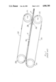
- FIG. 1 is a schematic side elevational view of the moving mold casting region C and the two belts in a prior art continuous metal casting machine of the twin-belt type.
- FIG. 2 is a schematic elevational view of the exit (downstream) end of the twin-belt caster of FIG. 1, FIG. 2 illustrates tilting (angle ⁇ ) of the respective exit pulley roll axis for steering the associated casting belt.
- FIG. 3 is a schematic top plan view of the upper casting belt and its two pulley rolls 20 and 29 for illustrating the manner in which tilting of the axis of an exit pulley roll 20 causes the revolving belt to be steered as a consequence of its resulting slightly oblique approach to the upstream pulley roll 29.
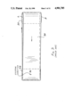
- FIG. 4 is a side elevational view of the portion of the casting region immediately upstream of the exit pulley rolls, being shown considerably enlarged as compared with FIG. 1.
- This FIG. 4 shows the belt-support platens extending between the last back-up rollers 28 and the exit pulley rolls 20 and 22.
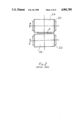
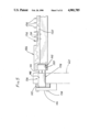
- FIG. 5 is a partial elevational and partial sectional view of the lower belt-support platen as seen looking in the upstream direction at 5--5 in FIG. 4.
- FIG. 5 shows the fins of the lower platen for allowing cooling water to flow at high velocity along the inner surface of the lower casting belt (not shown in FIG. 5).
- FIG. 6 is a schematic side elevational view similar to FIG. 1 for illustrating that lateral skew steering enables the casting belts to hug the cast product between the last back-up rollers and the exit pulley rolls, because clearance is no longer needed for tilting the axis of each exit pulley roll in a plane perpendicular to the casting plane.
- FIG. 7 is a schematic top plan view of the upper casting belt and its two pulley rolls 20 and 29 for illustrating the manner in which lateral skew steering of the exit pulley roll causes the revolving belt 24 to be steered. This FIG. 7 is contrasted with FIG. 3.
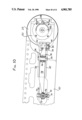
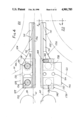
- FIG. 8 is a plan view showing the lateral skew steering and belt tensioning apparatus for the lower casting belt.
- FIG. 9 is an enlargement of a portion of FIG. 8 for illustrating the lateral skew steering apparatus more clearly.
- FIG. 10 is a side elevational view of the apparatus of FIG. 9.
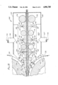
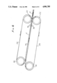
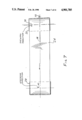
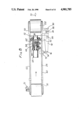
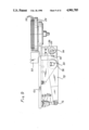
- FIG. 11 is a side elevational view, shown partly in section, of the exit containment and cooling apparatus for the cast product exiting from the twin-belt caster.
- twin-belt casting machines as illustrated in FIG. 1, the upper and lower casting belts 24 and 26 have each been revolved by two main pulley rolls; whereas earlier twin-belt casters, as shown in the patents discussed in the introduction, sometimes employed more than two main pulley rolls for each belt.
- the upper and lower belts 24 and 26 are driven by the entrance pulley rolls 29 and 30, respectively, and the belts are tensioned and steered by the exit pulley rolls 20 and 22.
- the casting belts 24 and 26 are guided and restrained as moving mold members by multiple finned backup rollers 28 (only two are shown in FIG. 1 for clarity of illustration) so that the opposed belt casting or mold surfaces are maintained in a preselected relationship throughout the length of the moving mold region C.
- These finned backup rollers 28 are of the type shown and described in U.S. Pat. No. 3,167,830.
- a flexible, endless side moving retaining dam 32 (FIG. 11), usually called an edge dam, is disposed on each side of the mold region for confining the molten metal 34.
- the casting belts 24 and 26 are normally parallel to each other through the mold region C up to the last back-up rollers 28 (FIG. 1).
- the casting belts in recent prior art twin-belt casters diverged from the exiting cast product P after passing the last pair of backup rollers 28, in order to provide clearance for the steering action being accomplished by tilting the exit pulley rolls 20 and 22, as indicated by the angle ⁇ .
- the belts 24 and 26 were steered by tilting the axis of the respective exit pulley roll 20 and 22 in the plane perpendicular to the plane of the casting region C, as shown by ⁇ in FIG. 2.
- This tilting of an exit pulley roll caused the steered belt 24 to approach the entrance pulley 29 slightly obliquely.
- the casting belt 24 would be caused to be steered in the direction 36.
- the belt would be steered in the opposite direction if end B were raised while end A were lowered.
- the axis of the exit pulley roll for example the roll 20 in FIG. 7, is skewed in a plane parallel with the plane of the casting region and in a plane passing through (coplanar with) the axis of entrance pulley roll 29. Skewing in the direction of the arrow 38--counterclockwise as seen from above--causes the belt 24 to be steered in the direction of the arrow 40. Conversely, skewing of the exit pulley roll in the opposite direction produces steering in the opposite direction from arrow 40.
- the skewing of the exit pulley roll 20 causes the revolving belt 24 to approach the entrance pulley roll 29 slightly obliquely and thus causes the belt to progress along the entrance pulley in the desired axial direction for keeping the belt in its desired lateral position in the twin-belt caster. Moreover, the belt is also immediately shifted laterally in the desired steering direction by the lateral skewings of a yoke-mounted exit pulley roll, as will be explained later.
- this lateral skew steering By virtue of this lateral skew steering, the casting belts 24 and 26 are enabled to hug the product P being cast, as shown in FIG. 6, all of the way to the exit pulley rolls 20 and 22, where the belts start to wrap upon the pulley. Thus, there is provided an effective increase in the moving mold length, plus a continuity of heat transfer out of the product being cast. Also, this lateral skew steering enables each casting belt 24 and 26 to be slidably supported adjacent to the caster exit pulley 20 and 22 by means of finned platens as shown in FIGS. 4 and 5, to be described later.
- FIGS. 8, 9 and 10 show apparatus for producing the lateral skew steering action described above, and such apparatus will be described for the lower belt 26 shown in dashed outline in FIG. 8.
- the belt 26 is revolved around the entrance and exit pulley rolls 30 and 22 by driving the entrance pulley roll 30, as indicated by the drive arrow 31.
- the arrow 33 indicates the exiting direction of the cast product P (FIG. 6).
- the exit pulley roll 22 is carried by a yoke 50 having a slidably mounted support shaft 52. This shaft 52 is mounted in bushings 54 and 56 within a cylindrical support 58 secured to a transverse frame member 62 of the frame 60 of the carriage for the lower casting belt 26.
- a large hydraulic-actuated cylinder 64 secured to the support 58 and having a piston rod 66 pinned to the longitudinally disposed, laterally constrained but slidable yoke shaft 52.
- the piston rod 66 extends into a hollowed socket 68 within the upstream end of the slidable yoke shaft and is attached to this shaft by a pin 70.
- Skewing of the yoke 50 is produced by a hydraulic-actuated steering cylinder 72 (FIG. 8) mounted on the carriage frame 60 and having its piston rod 74 connected by a pivot 76 to a steering lever 78.
- This lever 78 has a fulcrum pivot 80 on a bracket 82 secured to the carriage frame 60. The oposite end of this lever 78 is connected by a pivot 84 to a housing 86 fastened to the yoke 50.
- this steering lever 78 is a lever of the first class, and its effort arm driven by the piston rod 74 is considerably longer than its load arm connected to the yoke 50 via housing 86.
- this lever 78 there is a mechanical advantage provided by this lever 78 in moving the housing 86 and yoke 50, as indicated by the double-ended arrow 88.
- the action of the steering cylinder 72 is alternately to push, pull, or be neutral, in response to steering commands.
- the force 88 so applied to the steel yoke 50 causes the yoke to undergo an elastic angular deflection or skew that is in the plane defined by the axes of rotation of the pulley rolls 22 and 30, i.e., coplanar with that plane--hence the designation coplanar (or lateral) skew steering.
- the amount is normally 0.020 of an inch (0.5 of a millimeter). This represents an angular deflection of about 1/1000 of a radian or about 3.4 minutes or arc.
- the upper limit of useful angular deflection has not been explored but is believed to lie within 3/1000 of a radian or 10 minutes of arc.
- the preferred force-applying means at the end of the effort arm of the lever 78--the steering cylinder 72-- is a short stroke cylinder, sometimes called a "kicker cylinder,” having a total stroke of only about 1/4 of an inch (6 millimeters).
- the belt-tensioning apparatus is essentially isolated from the yoke 50 in regard to lateral skewing force and motion 88.
- the belt-tensioning apparatus does not resist or impede the lateral skew steering action 88.
- each exit pulley roll advantageously provides an effective mounting point M (FIG. 7), located upstream from the respective exit pulley roll, with said mounting point and the axis of the respective exit pulley roll defining a plane approximately parallel with the plane of the casting region C (FIG. 6).
- FIGS. 9 and 10 show that the steering cylinder 72 is mounted on trunnions 90 carried by bearing blocks 92 fastened to the carriage frame 60.
- the bracket 82 straddles the steering lever 78, which is mounted on sleeve bearings 94 and is positioned on its fulcrum pivot 80 by spacing washers 96. It is noted in FIG. 10 that the portion of the steering lever 78 near the fulcrum pivot 80 is increased in section for providing added strength to resist the bending moment involved in such a lever.
- the pivot 84 is mounted on a slide block 100 carried in the housing 86 and slidable in an upstream/downstream relationship relative to the housing 86.
- FIG. 9 shows the fins 102 on the exit pulley roll 22 for allowing high velocity cooling water (not shown) travelling along the inside surface of the revolving casting belt 26 (not shown in FIG. 9) to be removed by flowing in the grooves between these fins on the pulley roll 22.
- high velocity cooling water (not shown) travelling along the inside surface of the revolving casting belt 26 (not shown in FIG. 9)
- FIG. 9 shows the fins 102 on the exit pulley roll 22 for allowing high velocity cooling water (not shown) travelling along the inside surface of the revolving casting belt 26 (not shown in FIG. 9) to be removed by flowing in the grooves between these fins on the pulley roll 22.
- a pulley roll bearing (not shown) is carried in a rotatable eccentric member 104.
- This eccentric mounting 104 for the pulley roll bearing is rotated into a desired adjusted position and then is secured in place by keeper pins 106 held in a retainer 108 and engaging in socket holes 110 in the eccentric mounting member 104.
- FIGS. 4 and 5 there are shown an upper and lower support platen 124 and 126, respectively, for the upper and lower casting belts 24 and 26 (FIG. 6).
- the upper and lower exit pulley rolls 20 and 22 are shown in dashed outline, and their fins are indicated at 102.
- the upper and lower carriage frames are shown in dashed outline at 61 and 60, respectively.
- the upper platen 124 is mounted to the upper carriage frame 61 by means of eccentrically adjustable mounting shafts 127 and 128. Both of these shafts are captured by a block 129 shown in dashed outline and being fastened to the carriage frame 61 by machine screws 130.
- the upstream shaft 127 is captured vertically by a slider 132 which is slidingly received in a socket recess 134 extending in the upstream/downstream direction in the upper platen 124 for facilitating eccentrically adjustable mounting of this platen in the twin-belt machine.
- This upper platen includes multiple relatively narrow fins 136 extending in the upstream/downstream direction (left/right in FIG. 4) and with their working surfaces coplanar with the inside surface of the respective casting belt.
- the fins restrain bulging of the upper casting belt (not shown) while accommodating high velocity flow of cooling water in the downstream direction along the inside surface of the upper casting belt.
- the fins of each respective platen 124 and 126 are connected with each other by a web 135.
- the web is omitted in the areas 141 to provide clearance for meshing with the circular fins 102 of the respective exit rolls 20 and 22.
- the lower platen 126 is mounted to the lower carriage frame 60 by means of eccentrically adjustable mounting shafts 137 and 138.
- the upstream shaft 137 is held by a clamp 139 tightened by a clamp screw 140.
- the downstream shaft 138 is held by another clamp 142 tightened by a clamp screw 144.
- a block 146 is secured by screws 154 to the exterior of the lower carriage frame adjacent to the shaft clamps 139 and 142, to adjustably capture them.
- the eccentric 150 of the downstream shaft 128 for the upper platen 126 is shown in dashed outline in FIG. 4.
- the eccentric 150 of the downstream shaft 138 for the lower platen 126 is shown in FIG. 5.
- These eccentrics 150 are rotatably received in sockets 152 in the respective platens.
- Each adjustable mounting shaft 127, 128, 137 and 138 includes an exposed concentric hexagonal section 143, to which a wrench may be applied for adjusting the orientation of the eccentrics 150 and hence the vertical position of the respective platens.
- FIG. 4 shows the platens 124 and 126 extending horizontally in the upstream/downstream direction. It is to be understood that the casting plane C of this twin-belt caster and of these platens are inclined downwardly in the downstream direction at a suitable angle, for example 6 degrees to the horizontal, as illustrated in FIG. 6.
- FIG. 5 a portion of the lower platen 126 as seen looking in the direction 5--5 in FIG. 4.
- a portion of the lower carriage frame 60 is shown in dashed outline.
- the eccentrically adjustable mounting shaft 138 is seen extending through a mounting hole 148 in the frame 60 and terminating in an eccentric cylindrical end 150 received in a hole 152 in the platen 126.
- a section of mounting shaft 138 is shaped hexagonally to provide for a wrench to adjust the vertical position of platen 126.
- the platen fins 136 may be provided by removable inserts such as indicated at 156 and held by screws 158.
- the cast product P issuing from the twin-belt caster, is contained and supported by exit containment and supporting apparatus 160 positioned immediately adjacent to the revolving casting belts 24 and 26 at the exit E from the casting machine.
- the purpose of this apparatus 160 is to resist bulging of the relatively thin cast shell 162 which could result from metallostatic pressure of the still molten interior 34 due to the high-speed casting operation and to provide direct spray cooling of the cast product P.
- this product is a steel slab having a thickness of the order of about one inch, it is estimated that its molten interior or liquid center 34 may extend downstream from the exit E for a distance of up to about 10 feet in such high-speed continuous casting operation.
- the cast product P and its exit apparatus 160 are shown in a horizontal relationship in FIG. 11. It is to be understood that they are inclined downwardly in the downstream direction to match the angle of the casting plane C (FIG. 6).
- the exit apparatus 160 comprises: a spray chamber enclosure 164 having suitable exhaust ducting and drainage (not shown); pressurized coolant water supply connections 166, 167 for supplying upper and lower spray manifolds 168, 169 with multiple nozzles to be described; and a plurality of opposed pairs of support and containment rollers 170, 172, 174 and 176.
- Pressurized cooling water 178 is supplied through the connections 166 and 167 under a pressure in the range from about 30 pounds per square inch (p.s.i.) to about 120 p.s.i. into the spray manifolds 168, 169.
- These manifolds 168 and 169 span across the full width of the cast product and have multiple internally threaded pipe couplings 180 welded into ports in the wall of the respective manifold and aimed perpendicularly to the cast product.
- a spray nozzle 182 for directing a uniformly distributed conical pattern of spray 184 of cooling water onto the cast shell 162.
- these nozzles are "Full Jet”® nozzles obtainable from Spraying System Company of Wheaton, Ill. 60187, designed for producing a full cone of spray 184 with uniform distribution of the spray pattern.
- the nozzles 182 are spaced laterally at uniform intervals in three rows extending across the full width of the cast slab P and are sufficiently closely spaced in their respective rows for their sprays 184 to overlap in the lateral direction for producing intense cooling.
- the second row of nozzles 182 is positioned midway between the axes of the second and third rollers 172 and 174, and the third row of nozzles 182 is positioned for their spray patterns to be located midway between the curving surfaces of the third and fourth rollers 174 and 176.
- the first row of nozzles 182 is positioned approximately midway between the first and second rollers 170, 172, but is offset somewhat in the downstream direction to provide clearance between the spray manifold and the curvature of the revolving casting belts 24, 26.
- the first opposed pair of rollers 170 have the smallest diameter, for example of the order of 1.75 to 2.00 inches. It is to be understood that each of these rollers 170 is segmented into relatively short segments having intermediate supports and bearings (not shown) for resisting deflection of these relatively small diameter rollers which extend across the full width of the casting product P.
- Coolant supply conduits 186 and 187 project into the region between the curving outer surfaces of the respective casting belts 24 and 26 traveling around the exit pulley rolls 20 and 22.
- These conduits 186 and 187 carry multiple spray nozzles 188 spaced uniformly laterally across the width of the cast slab P for projecting their sprays 190 in laterally overlapping relationship for intense cooling.
- the nozzles 188 are aimed in the upstream direction toward the caster exit E at an impingement angle of about 45 degrees relative to the plane of the cast product, for causing their sprays 190 to impinge against the cast shell 162 over essentially the entire areas of this shell between the exit E and the first rollers 170.
- the impingement angle of nozzles 188 may be substantially less than 45 degrees but should not be less than about 10 degrees so as not to force the spray to penetrate beyond the exit E into the mold region C.
- lower conduit means 187 are arranged to clear the two side dams 32 (only one is seen in FIG. 11) which are travelling out of the caster exit E, straddling the cast product and then curving downwardly, being carried by the outer surface of the lower casting belt 26.
- rollers 172 and 174 are shown with the same diameter, for example 3 inches each, while the fourth rollers 176 are largest, for example each with a 4 inch diameter. Because of their increased stiffness against bending deflection as compared with rollers 170, the rollers 172 and 174 include fewer segments and fewer intermediate supports and bearings than the first, smallest rollers 170, while the largest fourth rollers 176 may be unsegmented, depending upon the span distance across the full width of the cast slab P.
- the containment, support and cooling apparatus 160 shown in FIG. 11 extends for a distance of about 36 inches from the caster exit E.
- the first set of opposed rollers 170 are shown with their centers positioned within less than twelve inches, for example about 91/8 inches, from the exit E.
- the second set of opposed rollers 172 are shown positioned less than ten inches for example about 71/4 inches, from rollers 170 on a center-to-center measure, with the third rollers 174 being less than ten inches for example about 71/2 inches, on centers from the second rollers 172 and the fourth rollers 176 being about 73/4 inches on centers from the third rollers 174.
- these four sets of rollers all have center-to-center spacings in the range, for example, from about 7 to about 8 inches.
- the distance between rollers 174 and 176 can be increased up to 14 inches without permitting undesired bulging of the cast shell 162.
- pinch-roll apparatus Down the pass line about 16 feet from the caster exit E may be located pinch-roll apparatus followed by a rolling miss as discussed in the introduction. Additional similar containment, support and cooling apparatus is employed downstream from this apparatus 160 for continuously casting and rolling a steel slab product P.
- Such apparatus extends as far as the pinch rolls, comprising pairs of opposed rollers, similar to rollers 176 but much larger in diameter, with direct impingement cone spray nozzles positioned between these rollers, similar to the nozzles 182.
- the outer surfaces (the casting surfaces) of the belts 24 and 26 become wet from the sprays 190.
- Such thorough drying of the outer belt surfaces is accomplished by air blasts; the initial blasts nearer the exit pulley rolls 20, 22 are air at room temperature.
- the final blasts nearer the entrance pulley rolls 29, 30 are heated air at sufficiently high temperature for completely, evaporating any residual moisture clinging to the belt surface.
Landscapes
- Engineering & Computer Science (AREA)
- Mechanical Engineering (AREA)
- Continuous Casting (AREA)
- Moulding By Coating Moulds (AREA)
Abstract
Description
Claims (24)
Priority Applications (6)
| Application Number | Priority Date | Filing Date | Title |
|---|---|---|---|
| US07/224,058 US4901785A (en) | 1988-07-25 | 1988-07-25 | Twin-belt continuous caster with containment and cooling of the exiting cast product for enabling high-speed casting of molten-center product |
| EP89113637A EP0352716B1 (en) | 1988-07-25 | 1989-07-24 | Twin-belt continuous caster with containment and cooling of the exiting cast product for enabling high-speed casting of molten-center product |
| DE89113637T DE68912671T2 (en) | 1988-07-25 | 1989-07-24 | Double-strip continuous casting machine with guide and cooling for the casting product for high-speed casting of products with a liquid core. |
| JP1192429A JPH02165848A (en) | 1988-07-25 | 1989-07-25 | Method and apparatus for continuous |
| CA000606598A CA1330701C (en) | 1988-07-25 | 1989-07-25 | Twin-belt continuous caster with containment and cooling of the exiting cast product for enabling high-speed casting of molten-center product |
| CN89106110.XA CN1039746A (en) | 1988-07-25 | 1989-07-25 | Method and apparatus with enabling high-speed casting with belt continuous caster |
Applications Claiming Priority (1)
| Application Number | Priority Date | Filing Date | Title |
|---|---|---|---|
| US07/224,058 US4901785A (en) | 1988-07-25 | 1988-07-25 | Twin-belt continuous caster with containment and cooling of the exiting cast product for enabling high-speed casting of molten-center product |
Publications (1)
| Publication Number | Publication Date |
|---|---|
| US4901785A true US4901785A (en) | 1990-02-20 |
Family
ID=22839131
Family Applications (1)
| Application Number | Title | Priority Date | Filing Date |
|---|---|---|---|
| US07/224,058 Expired - Fee Related US4901785A (en) | 1988-07-25 | 1988-07-25 | Twin-belt continuous caster with containment and cooling of the exiting cast product for enabling high-speed casting of molten-center product |
Country Status (6)
| Country | Link |
|---|---|
| US (1) | US4901785A (en) |
| EP (1) | EP0352716B1 (en) |
| JP (1) | JPH02165848A (en) |
| CN (1) | CN1039746A (en) |
| CA (1) | CA1330701C (en) |
| DE (1) | DE68912671T2 (en) |
Cited By (15)
| Publication number | Priority date | Publication date | Assignee | Title |
|---|---|---|---|---|
| US5437326A (en) * | 1992-08-18 | 1995-08-01 | Hazelett Strip-Casting Corporation | Method and apparatus for continuous casting of metal |
| WO1998001247A1 (en) * | 1996-07-10 | 1998-01-15 | Hazelett Strip-Casting Corporation | Permanent-magnetic hydrodynamic methods and apparatus for stabilizing continuous casting belts |
| US5725046A (en) * | 1994-09-20 | 1998-03-10 | Aluminum Company Of America | Vertical bar caster |
| EP0868953A3 (en) * | 1997-03-04 | 1999-02-03 | Hazelett Strip-Casting Corporation | Method and apparatus for steering a casting belt in a continuous metal-casting machine |
| US5967223A (en) * | 1996-07-10 | 1999-10-19 | Hazelett Strip-Casting Corporation | Permanent-magnetic hydrodynamic methods and apparatus for stabilizing a casting belt in a continuous metal-casting machine |
| US6086242A (en) * | 1998-02-27 | 2000-07-11 | University Of Utah | Dual drive planetary mill |
| US6250370B1 (en) * | 1998-05-28 | 2001-06-26 | Kawasaki Steel Corporation | Method for water-cooling hot metal slabs |
| US6264767B1 (en) | 1995-06-07 | 2001-07-24 | Ipsco Enterprises Inc. | Method of producing martensite-or bainite-rich steel using steckel mill and controlled cooling |
| GB2366531A (en) * | 2000-09-11 | 2002-03-13 | Daido Metal Co | Continuous casting of aluminiun bearing alloy including cooli ng |
| US6374901B1 (en) | 1998-07-10 | 2002-04-23 | Ipsco Enterprises Inc. | Differential quench method and apparatus |
| US7156147B1 (en) | 2005-10-19 | 2007-01-02 | Hazelett Strip Casting Corporation | Apparatus for steering casting belts of continuous metal-casting machines equipped with non-rotating, levitating, semi-cylindrical belt support apparatus |
| US20110020972A1 (en) * | 2009-07-21 | 2011-01-27 | Sears Jr James B | System And Method For Making A Photovoltaic Unit |
| US20110036531A1 (en) * | 2009-08-11 | 2011-02-17 | Sears Jr James B | System and Method for Integrally Casting Multilayer Metallic Structures |
| US20110036530A1 (en) * | 2009-08-11 | 2011-02-17 | Sears Jr James B | System and Method for Integrally Casting Multilayer Metallic Structures |
| CN102470427A (en) * | 2009-06-27 | 2012-05-23 | Sms西马格股份公司 | Apparatus and method for horizontal casting of metal strip |
Families Citing this family (4)
| Publication number | Priority date | Publication date | Assignee | Title |
|---|---|---|---|---|
| US5671801A (en) * | 1996-01-11 | 1997-09-30 | Larex A.G. | Cooling system for a belt caster and associated methods |
| RU2461441C2 (en) * | 2007-09-25 | 2012-09-20 | Улвак, Инк. | Device for secondary cooling of cast thin strips from neodymium-, iron- and boron-based alloys and device for casting said strips |
| CN104057049B (en) * | 2014-07-09 | 2016-06-15 | 北京科技大学 | The continuous casting machine fan-shaped segment of the big pressure of continuous casting billet solidifying end and big reduction method thereof |
| CN117428168B (en) * | 2023-12-21 | 2024-03-12 | 靖江市恒友汽车部件制造有限公司 | Casting die for bracket of automobile brake caliper body and processing method thereof |
Citations (4)
| Publication number | Priority date | Publication date | Assignee | Title |
|---|---|---|---|---|
| US4367783A (en) * | 1980-10-27 | 1983-01-11 | Hazelett Strip-Casting Corporation | Method and apparatus for continuous casting of metal under controlled load conditions |
| US4679612A (en) * | 1984-12-07 | 1987-07-14 | Fried. Krupp Gesellschaft Mit Beschrankter Haftung | Guide assembly for a twin-belt continuous casting mold |
| JPH0649840A (en) * | 1991-07-05 | 1994-02-22 | Nippon Steel Corp | Construction method of steel pipe foundation pile for preventing liquefaction |
| JPH06224845A (en) * | 1993-01-28 | 1994-08-12 | Sharp Corp | Cordless automatic answering telephone set |
Family Cites Families (2)
| Publication number | Priority date | Publication date | Assignee | Title |
|---|---|---|---|---|
| US3310849A (en) * | 1965-02-15 | 1967-03-28 | Hazelett Strip Casting Corp | Continuous metal casting apparatus |
| US3949805A (en) * | 1973-04-12 | 1976-04-13 | Hazelett Strip-Casting Corporation | Symmetrical belt tensioning system and apparatus for twin-belt continuous casting machines |
-
1988
- 1988-07-25 US US07/224,058 patent/US4901785A/en not_active Expired - Fee Related
-
1989
- 1989-07-24 EP EP89113637A patent/EP0352716B1/en not_active Expired - Lifetime
- 1989-07-24 DE DE89113637T patent/DE68912671T2/en not_active Expired - Fee Related
- 1989-07-25 CA CA000606598A patent/CA1330701C/en not_active Expired - Fee Related
- 1989-07-25 JP JP1192429A patent/JPH02165848A/en active Pending
- 1989-07-25 CN CN89106110.XA patent/CN1039746A/en active Pending
Patent Citations (4)
| Publication number | Priority date | Publication date | Assignee | Title |
|---|---|---|---|---|
| US4367783A (en) * | 1980-10-27 | 1983-01-11 | Hazelett Strip-Casting Corporation | Method and apparatus for continuous casting of metal under controlled load conditions |
| US4679612A (en) * | 1984-12-07 | 1987-07-14 | Fried. Krupp Gesellschaft Mit Beschrankter Haftung | Guide assembly for a twin-belt continuous casting mold |
| JPH0649840A (en) * | 1991-07-05 | 1994-02-22 | Nippon Steel Corp | Construction method of steel pipe foundation pile for preventing liquefaction |
| JPH06224845A (en) * | 1993-01-28 | 1994-08-12 | Sharp Corp | Cordless automatic answering telephone set |
Non-Patent Citations (2)
| Title |
|---|
| Petry, C. J. et al., Paper presented at the 28th Mechanical Working and Steel Processing Conference on Oct. 26 28, 1986, Pittsburgh, pp. 205 212. * |
| Petry, C. J. et al., Paper presented at the 28th Mechanical Working and Steel Processing Conference on Oct. 26-28, 1986, Pittsburgh, pp. 205-212. |
Cited By (23)
| Publication number | Priority date | Publication date | Assignee | Title |
|---|---|---|---|---|
| US5437326A (en) * | 1992-08-18 | 1995-08-01 | Hazelett Strip-Casting Corporation | Method and apparatus for continuous casting of metal |
| US5725046A (en) * | 1994-09-20 | 1998-03-10 | Aluminum Company Of America | Vertical bar caster |
| US6264767B1 (en) | 1995-06-07 | 2001-07-24 | Ipsco Enterprises Inc. | Method of producing martensite-or bainite-rich steel using steckel mill and controlled cooling |
| WO1998001247A1 (en) * | 1996-07-10 | 1998-01-15 | Hazelett Strip-Casting Corporation | Permanent-magnetic hydrodynamic methods and apparatus for stabilizing continuous casting belts |
| US5967223A (en) * | 1996-07-10 | 1999-10-19 | Hazelett Strip-Casting Corporation | Permanent-magnetic hydrodynamic methods and apparatus for stabilizing a casting belt in a continuous metal-casting machine |
| RU2188096C2 (en) * | 1996-07-10 | 2002-08-27 | Хэйзлетт Стрип-Кастинг Корпорейшн | Hydrodynamic process for stabilizing belt conveyors for continuous casting with use of permanent magnets and apparatus for performing the same |
| EP0868953A3 (en) * | 1997-03-04 | 1999-02-03 | Hazelett Strip-Casting Corporation | Method and apparatus for steering a casting belt in a continuous metal-casting machine |
| US6026887A (en) * | 1997-03-04 | 2000-02-22 | Hazelett Strip-Casting Corporation | Steering, tensing and driving a revolving casting belt using an exit-pulley drum for achieving all three functions |
| US6086242A (en) * | 1998-02-27 | 2000-07-11 | University Of Utah | Dual drive planetary mill |
| US6250370B1 (en) * | 1998-05-28 | 2001-06-26 | Kawasaki Steel Corporation | Method for water-cooling hot metal slabs |
| US6374901B1 (en) | 1998-07-10 | 2002-04-23 | Ipsco Enterprises Inc. | Differential quench method and apparatus |
| GB2366531A (en) * | 2000-09-11 | 2002-03-13 | Daido Metal Co | Continuous casting of aluminiun bearing alloy including cooli ng |
| US6471796B1 (en) | 2000-09-11 | 2002-10-29 | Daido Metal Company Ltd. | Method and apparatus for continuous casting of aluminum bearing alloy |
| GB2366531B (en) * | 2000-09-11 | 2004-08-11 | Daido Metal Co | Method and apparatus for continuous casting of aluminum bearing alloy |
| US7156147B1 (en) | 2005-10-19 | 2007-01-02 | Hazelett Strip Casting Corporation | Apparatus for steering casting belts of continuous metal-casting machines equipped with non-rotating, levitating, semi-cylindrical belt support apparatus |
| CN102470427A (en) * | 2009-06-27 | 2012-05-23 | Sms西马格股份公司 | Apparatus and method for horizontal casting of metal strip |
| US20120132390A1 (en) * | 2009-06-27 | 2012-05-31 | Sms Siemag Aktiengesellschaft | Device and method for horizontal casting of a metal band |
| US8807201B2 (en) * | 2009-06-27 | 2014-08-19 | Sms Siemag Aktiengesellschaft | Device and method for horizontal casting of a metal band |
| CN102470427B (en) * | 2009-06-27 | 2015-06-17 | Sms西马格股份公司 | Device and method for horizontal casting of a metal band |
| US20110020972A1 (en) * | 2009-07-21 | 2011-01-27 | Sears Jr James B | System And Method For Making A Photovoltaic Unit |
| US7888158B1 (en) | 2009-07-21 | 2011-02-15 | Sears Jr James B | System and method for making a photovoltaic unit |
| US20110036531A1 (en) * | 2009-08-11 | 2011-02-17 | Sears Jr James B | System and Method for Integrally Casting Multilayer Metallic Structures |
| US20110036530A1 (en) * | 2009-08-11 | 2011-02-17 | Sears Jr James B | System and Method for Integrally Casting Multilayer Metallic Structures |
Also Published As
| Publication number | Publication date |
|---|---|
| CA1330701C (en) | 1994-07-19 |
| EP0352716A1 (en) | 1990-01-31 |
| DE68912671D1 (en) | 1994-03-10 |
| DE68912671T2 (en) | 1994-05-05 |
| EP0352716B1 (en) | 1994-01-26 |
| JPH02165848A (en) | 1990-06-26 |
| CN1039746A (en) | 1990-02-21 |
Similar Documents
| Publication | Publication Date | Title |
|---|---|---|
| US4901785A (en) | Twin-belt continuous caster with containment and cooling of the exiting cast product for enabling high-speed casting of molten-center product | |
| US4002197A (en) | Continuous casting apparatus wherein the temperature of the flexible casting belts in twin-belt machines is controllably elevated prior to contact with the molten metal | |
| CN1212902C (en) | Feeding strip material | |
| EP0876231B1 (en) | Continuous chain caster and method | |
| US4921037A (en) | Method and apparatus for introducing differential stresses in endless flexible metallic casting belts for enhancing belt performance in continuous metal casting machines | |
| US4082101A (en) | Coolant nozzle apparatus in twin-belt continuous casting machines | |
| US7823623B2 (en) | Belt casting machine having adjustable contact length with cast metal slab | |
| US4632176A (en) | Apparatus for continuous strip casting of aluminum sheet material | |
| KR20090098384A (en) | Bender Segments for Continuous Casting | |
| US20030205356A1 (en) | Continuous chain caster and method | |
| US4008750A (en) | Continuous casting of metals | |
| JPH0839222A (en) | Twin roll continuous casting machine Temperature uniformity device for slab width direction | |
| JPH0757368B2 (en) | Roll cooling device for rolling mill | |
| JPS6232017B2 (en) | ||
| JPH0661598B2 (en) | Belt type continuous casting machine | |
| JP3794085B2 (en) | High temperature steel plate cooling device | |
| SU1400772A1 (en) | Guiding device of secondary cooling zone for continuous casting machine | |
| JP3284911B2 (en) | High temperature steel plate cooling system | |
| RU2022033C1 (en) | Device for cooling rectangular rolled stock | |
| JPH07110396B2 (en) | Twin belt type continuous casting machine | |
| JPH1024310A (en) | Guide device for shape | |
| JPS61159249A (en) | Belt type continuous casting machine | |
| JPH09192789A (en) | Belt type continuous casting method | |
| JPH0373606B2 (en) | ||
| JPH0323040A (en) | Belt type continuous casting apparatus |
Legal Events
| Date | Code | Title | Description |
|---|---|---|---|
| AS | Assignment |
Owner name: HAZELETT STRIP-CASTING CORPORATION, MALLETTS BAY, Free format text: ASSIGNMENT OF ASSIGNORS INTEREST.;ASSIGNOR:DYKES, CHARLES D.;REEL/FRAME:004957/0135 Effective date: 19880721 Owner name: HAZELETT STRIP-CASTING CORPORATION, A CORP. OF DE, Free format text: ASSIGNMENT OF ASSIGNORS INTEREST;ASSIGNOR:DYKES, CHARLES D.;REEL/FRAME:004957/0135 Effective date: 19880721 |
|
| AS | Assignment |
Owner name: USX CORPORATION, A DE CORP. Free format text: ASSIGNMENT OF ASSIGNORS INTEREST.;ASSIGNOR:DANIEL, SABAH S.;REEL/FRAME:004969/0171 Effective date: 19881101 Owner name: USX CORPORATION, STATELESS Free format text: ASSIGNMENT OF ASSIGNORS INTEREST;ASSIGNOR:DANIEL, SABAH S.;REEL/FRAME:004969/0171 Effective date: 19881101 |
|
| AS | Assignment |
Owner name: HAZELETT STRIP-CASTING CORPORATION, VERMONT Free format text: ASSIGNMENT OF ASSIGNORS INTEREST.;ASSIGNOR:WOOD, J. F. BARRY;REEL/FRAME:005172/0486 Effective date: 19891009 |
|
| REMI | Maintenance fee reminder mailed | ||
| FPAY | Fee payment |
Year of fee payment: 4 |
|
| SULP | Surcharge for late payment | ||
| FPAY | Fee payment |
Year of fee payment: 8 |
|
| REMI | Maintenance fee reminder mailed | ||
| LAPS | Lapse for failure to pay maintenance fees | ||
| STCH | Information on status: patent discontinuation |
Free format text: PATENT EXPIRED DUE TO NONPAYMENT OF MAINTENANCE FEES UNDER 37 CFR 1.362 |
|
| FP | Lapsed due to failure to pay maintenance fee |
Effective date: 20020220 |