US4901746A - Anticipating overspeed governor - Google Patents
Anticipating overspeed governor Download PDFInfo
- Publication number
- US4901746A US4901746A US07/211,876 US21187688A US4901746A US 4901746 A US4901746 A US 4901746A US 21187688 A US21187688 A US 21187688A US 4901746 A US4901746 A US 4901746A
- Authority
- US
- United States
- Prior art keywords
- speed
- speed responsive
- responsive means
- acceleration
- spool
- Prior art date
- Legal status (The legal status is an assumption and is not a legal conclusion. Google has not performed a legal analysis and makes no representation as to the accuracy of the status listed.)
- Expired - Fee Related
Links
- 230000001133 acceleration Effects 0.000 claims abstract description 29
- 230000004044 response Effects 0.000 claims description 8
- 230000008878 coupling Effects 0.000 claims description 7
- 238000010168 coupling process Methods 0.000 claims description 7
- 238000005859 coupling reaction Methods 0.000 claims description 7
- 230000003213 activating effect Effects 0.000 claims 2
- 230000007246 mechanism Effects 0.000 abstract description 7
- 238000012937 correction Methods 0.000 abstract description 5
- 230000008859 change Effects 0.000 description 2
- 230000000694 effects Effects 0.000 description 2
- 239000012530 fluid Substances 0.000 description 2
- 238000000034 method Methods 0.000 description 2
- 238000012986 modification Methods 0.000 description 2
- 230000004048 modification Effects 0.000 description 2
- 238000006073 displacement reaction Methods 0.000 description 1
- 230000002093 peripheral effect Effects 0.000 description 1
Images
Classifications
-
- G—PHYSICS
- G05—CONTROLLING; REGULATING
- G05D—SYSTEMS FOR CONTROLLING OR REGULATING NON-ELECTRIC VARIABLES
- G05D13/00—Control of linear speed; Control of angular speed; Control of acceleration or deceleration, e.g. of a prime mover
- G05D13/02—Details
- G05D13/04—Details providing for emergency tripping of an engine in case of exceeding maximum speed
-
- Y—GENERAL TAGGING OF NEW TECHNOLOGICAL DEVELOPMENTS; GENERAL TAGGING OF CROSS-SECTIONAL TECHNOLOGIES SPANNING OVER SEVERAL SECTIONS OF THE IPC; TECHNICAL SUBJECTS COVERED BY FORMER USPC CROSS-REFERENCE ART COLLECTIONS [XRACs] AND DIGESTS
- Y10—TECHNICAL SUBJECTS COVERED BY FORMER USPC
- Y10T—TECHNICAL SUBJECTS COVERED BY FORMER US CLASSIFICATION
- Y10T137/00—Fluid handling
- Y10T137/0971—Speed responsive valve control
- Y10T137/0989—Acceleration responsive valve control
Definitions
- the present invention is directed to a speed responsive control device and a method of operating such device.
- the invention relates to an overspeed governor for adjusting the blade pitch of a propulsor of an aircraft engine.
- the pitch of the propulsor blades is adjustable to prevent propulsor overspeed.
- an overspeed governor is required to prevent propulsor overspeed in the event of normal electronic control failure. Due to the high torque inertia ratio of the propulsor, rapid accelerations of the propulsor are possible. Normal flyweight governors can not respond fast enough to prevent a dangerous overspeed condition. Therefore, governing is required to begin before the normal point when rapid accelerations are present.
- An object of the present invention is to provide an improved speed responsive control device and a method of operating such device which solves the aforementioned problem. More particularly, an object of the invention is to provide an improved overspeed governor for adjusting the blade pitch of a propulsor of an aircraft engine which can respond quickly when there is a rapid acceleration of the propulsor so as to make the necessary blade pitch correction and prevent a dangerous overspeed condition.
- the improved speed responsive control device of the invention which comprises speed responsive means for actuating a member as a function of the speed of movement of the speed responsive means, and acceleration responsive means for actuating the member as a function of the acceleration of the speed responsive means.
- Coupling means is provided for moving the acceleration responsive means with the speed responsive means.
- the coupling means includes the member which is actuated as a function of the speed of movement of the speed responsive means and as a function of the acceleration of the speed responsive means by the acceleration responsive means.
- the coupling means further includes means for actuating the member in the same direction in response to the acceleration of the speed responsive means with a change in the direction of motion of the speed responsive means.
- the disclosed, preferred embodiment of the invention is an overspeed governor for adjusting the blade pitch of the propulsor of an aircraft engine comprising a flyweight governor which is rotated in response to rotation of the propulsor, a governor pilot valve with a spool valve which is axially moved in response to changes in the speed of movement of the propulsor and flyweight governor for adjusting the blade pitch of the propulsor and acceleration responsive means for axially moving the spool valve in response to acceleration of the propulsor and flyweight governor.
- the acceleration responsive means includes a flywheel adapted to be rotated with the valve spool and cam means between the flywheel and the valve spool for axially moving the valve spool in response to an acceleration of the flyweight governor.
- the cam means includes at least one cam slot in one of the flywheel and the valve spool and at least one follower in the other of the flywheel and the valve spool, the cam follower extending into the cam slot.
- the cam slot extends at an angle with respect to the longitudinal axis of the valve spool so that relative rotation between the flywheel and the valve spool upon acceleration results in an axial translation of the valve spool as the flywheel is held in an axially fixed position.
- Means are also provided for adjusting the cam means for axially moving the valve spool in the same direction in response to an acceleration of the propulsor and flyweight governor with a change in the direction of rotation of the flyweight governor and valve spool. This is accomplished using a second cam slot extending in a direction at right angles to the first cam slot and means for adjusting the flywheel and spool valve relative to one another so that the cam follower is adjustably positioned in a selected one of the two cam slots in accordance with the direction of rotation.
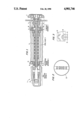
- FIG. 1 is a cross-sectional view taken along the longitudinal axis of an anticipating overspeed governor for adjusting the blade pitch of a propulsor of an aircraft engine according to the invention
- FIG. 2 is a cross-sectional view through the flywheel and spool valve of the overspeed governor of FIG. 1 taken along the line A--A;
- FIG. 3 is a plan view of a portion of the surface of the spool of the valve illustrating the locations and directions of the cam slots in the spool.
- an anticipating overspeed governor 1 of the invention as illustrated in FIGS. 1-3 is seen to comprise four major components. Namely, a flyweight governor 2 a hydraulic spool valve 3 that is actuated by the flyweights 4 of the flyweight governor 2, a flywheel acceleration sensing mechanism 5 that also actuates the spool valve 3 and a power drive unit (PDU) selector piston or mode selector mechanism 6.
- a flyweight governor 2 a hydraulic spool valve 3 that is actuated by the flyweights 4 of the flyweight governor 2, a flywheel acceleration sensing mechanism 5 that also actuates the spool valve 3 and a power drive unit (PDU) selector piston or mode selector mechanism 6.
- PDU power drive unit
- the flyweight governor 2 is rotated with a propulsor 7, shown only partially, of an unducted fan propulsor engine for an aircraft through a driving connection generally indicated at eight.
- the flyweights 4 of the governor 2 tend to move radially outward with increasing velocity of rotation causing the associated arms 9 to pivot about pivots 10 and, in turn, axially move a spool 11 of the hydraulic spool valve 3 to the right as shown in FIG. 1 against the bias of a spring 12.
- the axial movement of the spool 11 within the valve 3 controls the flow of hydraulic fluid for adjusting the pitch of the propulsor 7 to make the necessary blade pitch corrections in response to the sensed speed.
- the spool 11 of the valve 3 rotates with the flyweights 4 of the governor 2 through the spring 12 to minimize the spool drag and improve accuracy.
- the rotation of the spool 11 is transmitted to a flywheel 13 of the flywheel acceleration sensing mechanism 5 by way of a cam slot 14 formed in the outer peripheral surface of the spool 11 and a cam follower 15 mounted in the flywheel 13.
- a cam slot 14 formed in the outer peripheral surface of the spool 11 and a cam follower 15 mounted in the flywheel 13.
- the acceleration torque causes an axial force to be imparted to the spool 11 in a direction that adds to the flyweight force from the flyweight governor 2.
- the effect of the acceleration sensing mechanism 5 then is to govern the hydraulic spool valve 3 to begin the necessary blade pitch corrections before the speed governing caused by the flyweight governor 2 thus "anticipating" an overspeed condition in time to make the necessary blade pitch corrections and prevent a dangerous overspeed condition.
- the PDU selector piston 6 permits the axial displacement of the flywheel acceleration sensing mechanism with respect to the spool 11 so that the cam follower 15 can be selectively positioned in respective portions of the cam slot which are angled in opposite directions. This movement is accomplished by changing the respective sides of the piston 17 which are subjected to control pressure and to a return. That is, the cam follower is allowed to selectively operate on either section A or section B of the cam. This in effect changes the arithmetic sign of the acceleration sensing, allowing acceleration to be properly sensed for opposite rotation of the governor.
Landscapes
- Physics & Mathematics (AREA)
- General Physics & Mathematics (AREA)
- Engineering & Computer Science (AREA)
- Automation & Control Theory (AREA)
- Control Of Throttle Valves Provided In The Intake System Or In The Exhaust System (AREA)
Abstract
Description
Claims (5)
Priority Applications (1)
| Application Number | Priority Date | Filing Date | Title |
|---|---|---|---|
| US07/211,876 US4901746A (en) | 1988-06-27 | 1988-06-27 | Anticipating overspeed governor |
Applications Claiming Priority (1)
| Application Number | Priority Date | Filing Date | Title |
|---|---|---|---|
| US07/211,876 US4901746A (en) | 1988-06-27 | 1988-06-27 | Anticipating overspeed governor |
Publications (1)
| Publication Number | Publication Date |
|---|---|
| US4901746A true US4901746A (en) | 1990-02-20 |
Family
ID=22788645
Family Applications (1)
| Application Number | Title | Priority Date | Filing Date |
|---|---|---|---|
| US07/211,876 Expired - Fee Related US4901746A (en) | 1988-06-27 | 1988-06-27 | Anticipating overspeed governor |
Country Status (1)
| Country | Link |
|---|---|
| US (1) | US4901746A (en) |
Cited By (5)
| Publication number | Priority date | Publication date | Assignee | Title |
|---|---|---|---|---|
| WO1999056912A1 (en) * | 1998-05-01 | 1999-11-11 | United Technologies Corporation | Control system for blades for a variable pitch propeller |
| US20090180876A1 (en) * | 2008-01-11 | 2009-07-16 | Mt-Propeller Entwicklung Gmbh | Electrohydraulic propeller governor |
| RU2395713C1 (en) * | 2009-04-15 | 2010-07-27 | Открытое Акционерное Общество "Государственное Машиностроительное Конструкторское Бюро "Радуга" Имени А.Я. Березняка" | Centrifugal unfixture |
| RU2494021C1 (en) * | 2012-04-25 | 2013-09-27 | Открытое акционерное общество "Военно-промышленная корпорация "Научно-производственное объединение машиностроения" | Release |
| CN108388279A (en) * | 2018-02-12 | 2018-08-10 | 浙江中控技术股份有限公司 | A kind of control method and device of high-speed rotating machine equipment |
Citations (12)
| Publication number | Priority date | Publication date | Assignee | Title |
|---|---|---|---|---|
| US350595A (en) * | 1886-10-12 | Governor | ||
| US2472181A (en) * | 1944-07-07 | 1949-06-07 | Wright Aeronautical Corp | Propeller governor |
| GB674192A (en) * | 1949-11-26 | 1952-06-18 | Walker Brothers Wigan Ltd | Improvements in or relating to speed governor apparatus |
| US2816749A (en) * | 1953-12-12 | 1957-12-17 | Bbc Brown Boveri & Cie | Speed regulator for turbines |
| US2975794A (en) * | 1957-10-22 | 1961-03-21 | United Aircraft Corp | Constant speed propeller governor having propeller speed and acceleration sensitivity |
| US3322471A (en) * | 1965-10-06 | 1967-05-30 | Gen Motors Corp | Anti-skid brake device |
| US3370600A (en) * | 1965-09-09 | 1968-02-27 | Sundstrand Corp | Centrifugal governor for dual control of a servo-motor and a hydraulic switch |
| US3831615A (en) * | 1970-08-11 | 1974-08-27 | Piqua Aircraft Co | Electrically controlled governors |
| US3945199A (en) * | 1974-12-19 | 1976-03-23 | United Technologies Corporation | Flyweight speed sensor |
| US3955424A (en) * | 1975-03-10 | 1976-05-11 | Turbodyne Corporation | Integral mechanical governor |
| US4123942A (en) * | 1977-09-01 | 1978-11-07 | Rumyantsev Leonid A | Centrifugal governor |
| US4164235A (en) * | 1977-05-23 | 1979-08-14 | Sundstrand Corporation | Governor for controlling hydraulic transmission |
-
1988
- 1988-06-27 US US07/211,876 patent/US4901746A/en not_active Expired - Fee Related
Patent Citations (12)
| Publication number | Priority date | Publication date | Assignee | Title |
|---|---|---|---|---|
| US350595A (en) * | 1886-10-12 | Governor | ||
| US2472181A (en) * | 1944-07-07 | 1949-06-07 | Wright Aeronautical Corp | Propeller governor |
| GB674192A (en) * | 1949-11-26 | 1952-06-18 | Walker Brothers Wigan Ltd | Improvements in or relating to speed governor apparatus |
| US2816749A (en) * | 1953-12-12 | 1957-12-17 | Bbc Brown Boveri & Cie | Speed regulator for turbines |
| US2975794A (en) * | 1957-10-22 | 1961-03-21 | United Aircraft Corp | Constant speed propeller governor having propeller speed and acceleration sensitivity |
| US3370600A (en) * | 1965-09-09 | 1968-02-27 | Sundstrand Corp | Centrifugal governor for dual control of a servo-motor and a hydraulic switch |
| US3322471A (en) * | 1965-10-06 | 1967-05-30 | Gen Motors Corp | Anti-skid brake device |
| US3831615A (en) * | 1970-08-11 | 1974-08-27 | Piqua Aircraft Co | Electrically controlled governors |
| US3945199A (en) * | 1974-12-19 | 1976-03-23 | United Technologies Corporation | Flyweight speed sensor |
| US3955424A (en) * | 1975-03-10 | 1976-05-11 | Turbodyne Corporation | Integral mechanical governor |
| US4164235A (en) * | 1977-05-23 | 1979-08-14 | Sundstrand Corporation | Governor for controlling hydraulic transmission |
| US4123942A (en) * | 1977-09-01 | 1978-11-07 | Rumyantsev Leonid A | Centrifugal governor |
Cited By (7)
| Publication number | Priority date | Publication date | Assignee | Title |
|---|---|---|---|---|
| WO1999056912A1 (en) * | 1998-05-01 | 1999-11-11 | United Technologies Corporation | Control system for blades for a variable pitch propeller |
| US6077040A (en) * | 1998-05-01 | 2000-06-20 | United Technologies Corporation | Control system for blades for a variable pitch propeller |
| US20090180876A1 (en) * | 2008-01-11 | 2009-07-16 | Mt-Propeller Entwicklung Gmbh | Electrohydraulic propeller governor |
| US8075271B2 (en) * | 2008-01-11 | 2011-12-13 | Mt-Propeller Entwicklung Gmbh | Electrohydraulic propeller governor |
| RU2395713C1 (en) * | 2009-04-15 | 2010-07-27 | Открытое Акционерное Общество "Государственное Машиностроительное Конструкторское Бюро "Радуга" Имени А.Я. Березняка" | Centrifugal unfixture |
| RU2494021C1 (en) * | 2012-04-25 | 2013-09-27 | Открытое акционерное общество "Военно-промышленная корпорация "Научно-производственное объединение машиностроения" | Release |
| CN108388279A (en) * | 2018-02-12 | 2018-08-10 | 浙江中控技术股份有限公司 | A kind of control method and device of high-speed rotating machine equipment |
Similar Documents
| Publication | Publication Date | Title |
|---|---|---|
| CA3011876C (en) | Propeller control system for an aircraft | |
| US6053452A (en) | Compensation apparatus for main rotor torque | |
| EP0713008B1 (en) | Ram air turbine with secondary governor | |
| US6340290B1 (en) | Controllable pitch propeller with a fail safe increased pitch movement | |
| EP1270408B1 (en) | Backup governing system for a variable pitch propeller | |
| EP0601100A1 (en) | CONTROL OF THE ENGINE OF A HELICOPTER WITH ANTICIPATION OF THE LATERAL CYCLE TANGING. | |
| GB2144491A (en) | Propeller pitch control system | |
| US4901746A (en) | Anticipating overspeed governor | |
| US2472181A (en) | Propeller governor | |
| US3261405A (en) | Aircraft power control apparatus | |
| US2347104A (en) | Combined speed and velocity responsive variable pitch propeller mechanism | |
| US4142364A (en) | Back-up control for gas turbine engine | |
| US5391055A (en) | Propeller pitch change mechanism with impulse turbines | |
| JPH06510001A (en) | Helicopter engine control device with yaw input prediction function | |
| EP0398839B1 (en) | Helicopter control with multiple schedule rotor speed decay anticipator | |
| US2668414A (en) | Control apparatus for jet engines | |
| US3340952A (en) | Vehicle speed control system | |
| US2945547A (en) | Engine and vehicle speed control governor | |
| US3032985A (en) | Dual rotor governor | |
| US3482261A (en) | Manually variable pitch propeller | |
| US3518022A (en) | Propeller control mechanism | |
| US4986734A (en) | Overspeed protection system for aircraft fan engine | |
| US4164235A (en) | Governor for controlling hydraulic transmission | |
| US3431929A (en) | Snap-action flyweight governor for developing a speed sensitive pressure signal | |
| US4047589A (en) | Method and apparatus for closed loop acceleration control for vehicles |
Legal Events
| Date | Code | Title | Description |
|---|---|---|---|
| AS | Assignment |
Owner name: SUNDSTRAND CORPORATION, 4751 HARRISON AVE., P.O. B Free format text: ASSIGNMENT OF ASSIGNORS INTEREST.;ASSIGNOR:METCALF, JEFFREY D.;REEL/FRAME:004951/0740 Effective date: 19880602 Owner name: SUNDSTRAND CORPORATION, 4751 HARRISON AVE., P.O. B Free format text: ASSIGNMENT OF ASSIGNORS INTEREST;ASSIGNOR:METCALF, JEFFREY D.;REEL/FRAME:004951/0740 Effective date: 19880602 |
|
| REMI | Maintenance fee reminder mailed | ||
| LAPS | Lapse for failure to pay maintenance fees | ||
| FP | Lapsed due to failure to pay maintenance fee |
Effective date: 19930220 |
|
| STCH | Information on status: patent discontinuation |
Free format text: PATENT EXPIRED DUE TO NONPAYMENT OF MAINTENANCE FEES UNDER 37 CFR 1.362 |