US4901697A - Device for controlling an internal combustion engine - Google Patents
Device for controlling an internal combustion engine Download PDFInfo
- Publication number
- US4901697A US4901697A US07/347,888 US34788889A US4901697A US 4901697 A US4901697 A US 4901697A US 34788889 A US34788889 A US 34788889A US 4901697 A US4901697 A US 4901697A
- Authority
- US
- United States
- Prior art keywords
- segments
- internal combustion
- combustion engine
- receiving element
- permanent magnet
- Prior art date
- Legal status (The legal status is an assumption and is not a legal conclusion. Google has not performed a legal analysis and makes no representation as to the accuracy of the status listed.)
- Expired - Lifetime
Links
- 238000002485 combustion reaction Methods 0.000 title claims abstract description 18
- 238000002347 injection Methods 0.000 abstract 1
- 239000007924 injection Substances 0.000 abstract 1
- 230000005291 magnetic effect Effects 0.000 description 10
- 230000004907 flux Effects 0.000 description 8
- 238000000034 method Methods 0.000 description 5
- 230000008859 change Effects 0.000 description 3
- 238000001514 detection method Methods 0.000 description 3
- 238000010586 diagram Methods 0.000 description 3
- 230000008569 process Effects 0.000 description 3
- 230000003993 interaction Effects 0.000 description 2
- 230000001960 triggered effect Effects 0.000 description 2
- 230000005540 biological transmission Effects 0.000 description 1
- 238000010276 construction Methods 0.000 description 1
- 230000007423 decrease Effects 0.000 description 1
- 230000001419 dependent effect Effects 0.000 description 1
- 230000005294 ferromagnetic effect Effects 0.000 description 1
- 230000001939 inductive effect Effects 0.000 description 1
- 238000004519 manufacturing process Methods 0.000 description 1
- 239000002184 metal Substances 0.000 description 1
- 238000003801 milling Methods 0.000 description 1
- 230000004048 modification Effects 0.000 description 1
- 238000012986 modification Methods 0.000 description 1
- 230000001360 synchronised effect Effects 0.000 description 1
Images
Classifications
-
- F—MECHANICAL ENGINEERING; LIGHTING; HEATING; WEAPONS; BLASTING
- F02—COMBUSTION ENGINES; HOT-GAS OR COMBUSTION-PRODUCT ENGINE PLANTS
- F02P—IGNITION, OTHER THAN COMPRESSION IGNITION, FOR INTERNAL-COMBUSTION ENGINES; TESTING OF IGNITION TIMING IN COMPRESSION-IGNITION ENGINES
- F02P7/00—Arrangements of distributors, circuit-makers or -breakers, e.g. of distributor and circuit-breaker combinations or pick-up devices
- F02P7/06—Arrangements of distributors, circuit-makers or -breakers, e.g. of distributor and circuit-breaker combinations or pick-up devices of circuit-makers or -breakers, or pick-up devices adapted to sense particular points of the timing cycle
- F02P7/067—Electromagnetic pick-up devices, e.g. providing induced current in a coil
- F02P7/0675—Electromagnetic pick-up devices, e.g. providing induced current in a coil with variable reluctance, e.g. depending on the shape of a tooth
-
- G—PHYSICS
- G01—MEASURING; TESTING
- G01P—MEASURING LINEAR OR ANGULAR SPEED, ACCELERATION, DECELERATION, OR SHOCK; INDICATING PRESENCE, ABSENCE, OR DIRECTION, OF MOVEMENT
- G01P3/00—Measuring linear or angular speed; Measuring differences of linear or angular speeds
- G01P3/42—Devices characterised by the use of electric or magnetic means
- G01P3/44—Devices characterised by the use of electric or magnetic means for measuring angular speed
- G01P3/48—Devices characterised by the use of electric or magnetic means for measuring angular speed by measuring frequency of generated current or voltage
- G01P3/481—Devices characterised by the use of electric or magnetic means for measuring angular speed by measuring frequency of generated current or voltage of pulse signals
- G01P3/487—Devices characterised by the use of electric or magnetic means for measuring angular speed by measuring frequency of generated current or voltage of pulse signals delivered by rotating magnets
Definitions
- the invention relates to a device for controlling an internal combustion engine.
- devices for controlling an internal combustion engine of a motor vehicle particularly for controlling the ignition and the like, it is known to use sensor systems for detecting an angular position of a shaft of the internal combustion engine, particularly the crankshaft or the camshaft.
- Such systems are constructed e.g. as segment systems in and transmitter disks rotate with the shaft, which are provided at their circumference with a plurality of segments, i.e. elongated marked areas, proportional to the number of cylinders of the internal combustion engine.
- the number of segments amounts to one half of the number of cylinders.
- the number of segments is identical to the number of cylinders, since the crankshaft rotates at twice the speed of the camshaft, as is known.
- Every segment is assigned to a cylinder (n) of the internal combustion engine (two cylinders in the detection of the angular position of the crankshaft), and every ignition process is controlled as a function of the passage of a respective segment.
- a stationary receiving element the leading edge of the segment is detected, and the control processes for the internal combustion engine are triggered by a suitable time control over the entire length of the segment.
- segment systems with segments of equal dimensions have the disadvantage that an assignment, which is sufficient for a high-voltage distribution without the use of a distributor or for a dual-circuit (e.g. eight-cylinder engine) high-voltage distribution, is not possible.
- segment systems are known in which individual segments are divided by a number of teeth and tooth spaces and the signals produced by the teeth and tooth spaces, respectively, are fed to a control circuit. In so doing, the angular position of the shaft is determined by counting the passing teeth and tooth spaces, respectively. This method is costly and requires an additional counting device.
- the object of the invention is a device in which it is possible to assign the ignition pulses for a high-voltage distribution without the use of a distributor or for a dual-circuit high-voltage distribution with a single transmitter while maintaining the two electrical marks at the beginning and end of the segment.
- the object of the invention is achieved by assigning a permanent magnet to at least one segment as a mark which generates a signal which can be fed to a control circuit. Because of the resulting electric signals (markings), the cylinder groups can be clearly assigned in a high-voltage distribution without the use of a distributor. It is not necessary to change the profile of the segments, so that no cracks can occur as a result of of stresses particularly at high engine output moments.
- the total length of the segment having the permanent magnet thereon is equal to that of other segments.
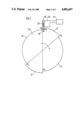
- FIG. 1 shows a basic view of a transmitter disk of the device according to the present invention
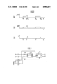
- FIGS. 2a, 2b, and 2c show a pulse diagram
- FIG. 3 shows a circuit diagram according to the present invention.
- a transmitter disk designated by 1, 1 rotates with a crankshaft or a camshaft of an internal combustion engine.
- the transmitter disk 10 comprises segments 11, 12 and spaces 13, 14 located between the latter. If two segments and two gaps, respectively, are provided, as in FIG. 1, and the transmitter disk 10 is fastened at the crankshaft of the internal combustion engine, it is suitable for devices for controlling four-cylinder engines.
- the segments 11, 12 have equal lengths the same angle of rotation and are located diametrically opposite one another.
- a permanent magnet 15, whose polarity is formed in the radial direction of the transmitter disk 10, is arranged at the end of the segment 11.
- the height of the permanent magnet 15 corresponds to the height of the segment 11 and is adpated to the surface curvature of the segment 11.
- the segment 11, including the permanent magnet 15, corresponds in length to the segment 12. Accordingly, the segment 11 is to be shortened, e.g. by milling, by an amount corresponding to the width of the permanent magnet 15 during production.
- a stationary receiving element 20 which is, in turn, in a operative connection with a control circuit 21 and, is located in the vicinity of the circumference of the transmitter disk 10.
- the type of interaction betweenn the transmitter disk 10 and receiving element 20 can vary to a great extent.
- the transmitter disk 10 can be punched out from a ferromagnetic sheet metal and an inductive sensor, which already has a magnetic flux in the rest state, is used as a receiving element 20.
- the receiving element 20 shown in FIG. 1 comprises a permanent magnet 22 and a coil 23.
- the receiving element 20 detects-e.g. in segment 12 the leading edge of the segment 12.
- the ignition process can then be triggered e.g. at the end of the segment 12 at an angular position corresponding to the trailing edge of the segment 12.
- FIG. 2 shows the time characteristic of signals generated by the segments 11, 12 and the spaces 13, 14, respectively, and by the permanent magnet 15.
- FIG. 2a shows a transmission of the rotational movement of the crankshaft ( ⁇ CS) to the rotation of the transmitter disk 10 as a function of the angle of rotation ( ⁇ ) of the transmitter disk.
- FIG. 2b the magnetic flux ( ⁇ ) produced in the receiving element 20 is shown as a function of the angle of rotation ( ⁇ ) of the transmitter disk 10. If the transmitter disk 10 moves in the clockwise direction, a change in the magnetic flux is produced at the leading edge of the segment 11, i.e. at the angular position ⁇ 1 , in the receiving element 20.
- the magnetic flux runs at the same height, while the segment 11 passes the receiving element 20; consequently, no voltage is induced.
- the receiving element 20 reaches the permanent magnet 15, i.e. the transmitter disk 10 is located in the angular position ⁇ .sub. 2, the magnetic flux increases again.
- the receiving element 20 reaches the end of the permanent magnet 15, i.e. the leading edge of the segment 11 and angular position ⁇ 3 , respectively, the magnetic flux decreases. While the space 13 now passes the receiving element 20, no substantial magnetic flux is generated.
- a change in the magnetic flux is now produced also by segment 12 at its leading edge as well as at its trailing edge, i.e. at the angular position ⁇ 4 and ⁇ 5 .
- FIG. 2c shows the pulses generated in the receiving element 20.
- a negative pulse is generated in each instance at the leading edge of the segments 11, 12, i.e. at the angular position ⁇ 1 and ⁇ 4 .
- the pulse is dependent on the polarity of the receiving element 20.
- the receiving element 20 reaches the permanent magnet in angular position ⁇ 2
- another negative pulse is produced.
- the receiving element 20 reaches the rear flank of the segments 11, 12, i.e. the transmitter disk 10 is located at angular position ⁇ 3 and ⁇ 5
- a positive pulse is produced. Due to the magnetic field of the permanent magnet 15, the positive pulse at position ⁇ 3 is greater than the pulse in position ⁇ 5 .
- the additional pulse produced in position ⁇ 2 , and the different pulse height at position ⁇ 3 can now be used as a mark.
- the voltages produced in the receiving element 20 at the edges of the segments 11 and 12, respectively, and in position ⁇ 2 by the permanent magnet 15, are fed to two input terminals E1 and E2 of the control circuit shown in the basic diagram in FIG. 3 via two Schmitt triggers having different switching thresholds.
- An inverter 27 is connected to the input terminal E1, to which the voltage U - is applied.
- a non-inverting driver stage 28 is connected to the input terminal E2 to which the voltage U + is applied.
- the output of the inverter 27 is connected with the inverting reset input of a flip-flop 29.
- the output of the driver stage 28 is connected to its inverting set input.
- a line leads from the output Q of the flip-flop 29 to the clear-enable input of a counter 30.
- the inverting clear enable input of the counter 30 is connected with the output of the driver stage 28.
- the voltage U - tapped prior to the inverter 27 is applied to the counter input of the counter 30.
- Lines lead from the two outputs of the counter 30 to the two cylinder groups of a four-cylinder engine.
- This circuit serves to achieve a synchronous pulse in order to enable an accurate assignment of the position of the transmitter disc relative to the respective rotation of the shaft already when starting the internal combustion engine.
- this principle of control is applicable to all engines with an even number of cylinders. In asymmetrical engines, it must be ensured that the asymmetry occurs within a crankshaft revolution.
Landscapes
- Engineering & Computer Science (AREA)
- Physics & Mathematics (AREA)
- Electromagnetism (AREA)
- Chemical & Material Sciences (AREA)
- Combustion & Propulsion (AREA)
- Mechanical Engineering (AREA)
- General Engineering & Computer Science (AREA)
- General Physics & Mathematics (AREA)
- Measurement Of Length, Angles, Or The Like Using Electric Or Magnetic Means (AREA)
- Ignition Installations For Internal Combustion Engines (AREA)
- Combined Controls Of Internal Combustion Engines (AREA)
Abstract
A device for controlling an internal combustion engine of a motor vehicle and comprising a transmitter disk which rotates with a shaft of the internal combustion engine relative an opposite stationary receiving element, the transmitter disk being provided at its circumference with a plurality of segments proportional to the number of cylinders, and a permanent magnet assigned to at least one of the segments for generating a marking signal to be fed to a control circuit for the ignition, injection and the like of the motor vehicle via the receiving element.
Description
The invention relates to a device for controlling an internal combustion engine. In devices for controlling an internal combustion engine of a motor vehicle, particularly for controlling the ignition and the like, it is known to use sensor systems for detecting an angular position of a shaft of the internal combustion engine, particularly the crankshaft or the camshaft.
Such systems are constructed e.g. as segment systems in and transmitter disks rotate with the shaft, which are provided at their circumference with a plurality of segments, i.e. elongated marked areas, proportional to the number of cylinders of the internal combustion engine. In the detection of the angular position of the crankshaft, the number of segments amounts to one half of the number of cylinders. In the detection of the angular position of the camshaft the number of segments is identical to the number of cylinders, since the crankshaft rotates at twice the speed of the camshaft, as is known. Every segment is assigned to a cylinder (n) of the internal combustion engine (two cylinders in the detection of the angular position of the crankshaft), and every ignition process is controlled as a function of the passage of a respective segment. In a stationary receiving element, the leading edge of the segment is detected, and the control processes for the internal combustion engine are triggered by a suitable time control over the entire length of the segment. On the other hand, segment systems with segments of equal dimensions have the disadvantage that an assignment, which is sufficient for a high-voltage distribution without the use of a distributor or for a dual-circuit (e.g. eight-cylinder engine) high-voltage distribution, is not possible.
In addition, segment systems are known in which individual segments are divided by a number of teeth and tooth spaces and the signals produced by the teeth and tooth spaces, respectively, are fed to a control circuit. In so doing, the angular position of the shaft is determined by counting the passing teeth and tooth spaces, respectively. This method is costly and requires an additional counting device.
In addition, if only a single tooth space is formed in a segment, there is the risk that the additional trailing edge will trigger an additional ignition.
In all devices mentioned here, at least one revolution is required when starting the internal combustion engine in order to detect an accurate assignment of the marking.
The object of the invention is a device in which it is possible to assign the ignition pulses for a high-voltage distribution without the use of a distributor or for a dual-circuit high-voltage distribution with a single transmitter while maintaining the two electrical marks at the beginning and end of the segment. The object of the invention is achieved by assigning a permanent magnet to at least one segment as a mark which generates a signal which can be fed to a control circuit. Because of the resulting electric signals (markings), the cylinder groups can be clearly assigned in a high-voltage distribution without the use of a distributor. It is not necessary to change the profile of the segments, so that no cracks can occur as a result of of stresses particularly at high engine output moments.
The total length of the segment having the permanent magnet thereon is equal to that of other segments.
The present invention as to its construction so to its method of operation, together with additional objects and advatnages thereof, will be best understood from the following description of the preferred embodiment with reference to the accompanying drawings.
FIG. 1 shows a basic view of a transmitter disk of the device according to the present invention;
FIGS. 2a, 2b, and 2c show a pulse diagram; and
FIG. 3 shows a circuit diagram according to the present invention.
In FIG. 1, a transmitter disk designated by 1, 1 rotates with a crankshaft or a camshaft of an internal combustion engine. At its circumference, the transmitter disk 10 comprises segments 11, 12 and spaces 13, 14 located between the latter. If two segments and two gaps, respectively, are provided, as in FIG. 1, and the transmitter disk 10 is fastened at the crankshaft of the internal combustion engine, it is suitable for devices for controlling four-cylinder engines. The segments 11, 12 have equal lengths the same angle of rotation and are located diametrically opposite one another. A permanent magnet 15, whose polarity is formed in the radial direction of the transmitter disk 10, is arranged at the end of the segment 11. The height of the permanent magnet 15 corresponds to the height of the segment 11 and is adpated to the surface curvature of the segment 11. The segment 11, including the permanent magnet 15, corresponds in length to the segment 12. Accordingly, the segment 11 is to be shortened, e.g. by milling, by an amount corresponding to the width of the permanent magnet 15 during production.
A stationary receiving element 20, which is, in turn, in a operative connection with a control circuit 21 and, is located in the vicinity of the circumference of the transmitter disk 10. The type of interaction betweenn the transmitter disk 10 and receiving element 20 can vary to a great extent. To provide for magnetic interaction, the transmitter disk 10 can be punched out from a ferromagnetic sheet metal and an inductive sensor, which already has a magnetic flux in the rest state, is used as a receiving element 20. The receiving element 20 shown in FIG. 1 comprises a permanent magnet 22 and a coil 23.
If the transmitter disk 10, as shown in FIG. 1, rotates in the clockwise direction, the receiving element 20 detects-e.g. in segment 12 the leading edge of the segment 12. The ignition process can then be triggered e.g. at the end of the segment 12 at an angular position corresponding to the trailing edge of the segment 12.
In order to illustrate the manner of operation of the device shown in FIG. 1, FIG. 2 shows the time characteristic of signals generated by the segments 11, 12 and the spaces 13, 14, respectively, and by the permanent magnet 15. FIG. 2a shows a transmission of the rotational movement of the crankshaft (Δ CS) to the rotation of the transmitter disk 10 as a function of the angle of rotation (α) of the transmitter disk. In FIG. 2b, the magnetic flux (ΔΦ) produced in the receiving element 20 is shown as a function of the angle of rotation (α) of the transmitter disk 10. If the transmitter disk 10 moves in the clockwise direction, a change in the magnetic flux is produced at the leading edge of the segment 11, i.e. at the angular position α1, in the receiving element 20. The magnetic flux runs at the same height, while the segment 11 passes the receiving element 20; consequently, no voltage is induced. When the receiving element 20 reaches the permanent magnet 15, i.e. the transmitter disk 10 is located in the angular position α.sub. 2, the magnetic flux increases again. When the receiving element 20 reaches the end of the permanent magnet 15, i.e. the leading edge of the segment 11 and angular position α3, respectively, the magnetic flux decreases. While the space 13 now passes the receiving element 20, no substantial magnetic flux is generated. In a manner analogous to segment 11, a change in the magnetic flux is now produced also by segment 12 at its leading edge as well as at its trailing edge, i.e. at the angular position α4 and α5.
FIG. 2c shows the pulses generated in the receiving element 20. A negative pulse is generated in each instance at the leading edge of the segments 11, 12, i.e. at the angular position α1 and α4. The pulse is dependent on the polarity of the receiving element 20. When the receiving element 20 reaches the permanent magnet in angular position α2, another negative pulse is produced. When the receiving element 20 reaches the rear flank of the segments 11, 12, i.e. the transmitter disk 10 is located at angular position α3 and α5, a positive pulse is produced. Due to the magnetic field of the permanent magnet 15, the positive pulse at position α3 is greater than the pulse in position α5. The additional pulse produced in position α2, and the different pulse height at position α3, respectively, can now be used as a mark.
The voltages produced in the receiving element 20 at the edges of the segments 11 and 12, respectively, and in position α2 by the permanent magnet 15, are fed to two input terminals E1 and E2 of the control circuit shown in the basic diagram in FIG. 3 via two Schmitt triggers having different switching thresholds. An inverter 27 is connected to the input terminal E1, to which the voltage U- is applied. On the other hand, a non-inverting driver stage 28 is connected to the input terminal E2 to which the voltage U+ is applied. The output of the inverter 27 is connected with the inverting reset input of a flip-flop 29. The output of the driver stage 28 is connected to its inverting set input. A line leads from the output Q of the flip-flop 29 to the clear-enable input of a counter 30. The inverting clear enable input of the counter 30 is connected with the output of the driver stage 28. In addition, the voltage U- tapped prior to the inverter 27 is applied to the counter input of the counter 30. Lines lead from the two outputs of the counter 30 to the two cylinder groups of a four-cylinder engine. This circuit serves to achieve a synchronous pulse in order to enable an accurate assignment of the position of the transmitter disc relative to the respective rotation of the shaft already when starting the internal combustion engine. Of course, this principle of control is applicable to all engines with an even number of cylinders. In asymmetrical engines, it must be ensured that the asymmetry occurs within a crankshaft revolution.
While the invention has been illustrated and described as embodied in a device for controlling an internal combustion engine, it is not intended to be limited to the details shown, since various modifications and structural changes may be made without departing in any way from the spirit of the present invention.
Without further analysis, the foregoing will so fully reveal the gist of the present invention that others can, by applying current knowledge, readily adapt it for various applications without omitting features that, from the standpoint of prior art, fairly constitute essential characteristics of the generic or specific aspects of this invention.
Claims (5)
1. A device for controlling an internal combustion engine having a shaft and a predetermined number of cylinders, said device comprising:
a transmitter disc mountable on the internal combustion engine shaft for joint rotation therewith for determining angular positions of said shaft, said transmitter disc having a plurality of circumferentially spaced segments proportional to the predetermined number of cylinders;
a stationary receiving element for generating control signals in accordance with positions of said segments; and
a control circuit for controlling the internal combustion engine in accordance with the control signals generated by said receiving element, said transmitter disc including a permanent magnet formed as a mark and associated with at least one of said plurality of segments for generating a signal communicated to said control circuit, an overall circumferential length of said one of said plurality of segments together with said permanent magnet being equal to that of others of said plurality of segments.
2. A device according to claim 1 wherein each of said plurality of segments has leading and trailing edges, said stationary receiving element generating control signals in accordance with positions of said leading and trailing edges.
3. A device according to claim 2 wherein said permanent magnet is polarized in a radial direction of said transmitter disc.
4. A device according to claim 2 wherein said one of said plurality of segments has an end, said permanent magnet being arranged at said end of said one of said plurality of segments.
5. A device according to claim 2 wherein said control circuit controls ignition of the internal combustion engine, said transmitter disc being formed for ignition with one of a high-voltage distribution without use of a distributor and a dual-circuit high-voltage distribution.
Applications Claiming Priority (2)
| Application Number | Priority Date | Filing Date | Title |
|---|---|---|---|
| DE3630271A DE3630271C2 (en) | 1986-09-05 | 1986-09-05 | Device for controlling an internal combustion engine |
| DE3630271 | 1986-09-05 |
Publications (1)
| Publication Number | Publication Date |
|---|---|
| US4901697A true US4901697A (en) | 1990-02-20 |
Family
ID=6308990
Family Applications (1)
| Application Number | Title | Priority Date | Filing Date |
|---|---|---|---|
| US07/347,888 Expired - Lifetime US4901697A (en) | 1986-09-05 | 1987-08-08 | Device for controlling an internal combustion engine |
Country Status (5)
| Country | Link |
|---|---|
| US (1) | US4901697A (en) |
| EP (1) | EP0323458B2 (en) |
| JP (1) | JP2541597B2 (en) |
| DE (2) | DE3630271C2 (en) |
| WO (1) | WO1988001692A1 (en) |
Cited By (2)
| Publication number | Priority date | Publication date | Assignee | Title |
|---|---|---|---|---|
| GB2254434A (en) * | 1991-04-03 | 1992-10-07 | Ametek Aerospace Products Inc | Low force flowmeter pick-off |
| US5243941A (en) * | 1991-07-29 | 1993-09-14 | Asmo Co., Ltd. | Actuator for engine idling control mechanism |
Families Citing this family (5)
| Publication number | Priority date | Publication date | Assignee | Title |
|---|---|---|---|---|
| JP2550397B2 (en) * | 1988-09-27 | 1996-11-06 | 三菱電機株式会社 | Signal generator for engine control |
| DE3918409C2 (en) * | 1989-06-06 | 1999-07-29 | Bosch Gmbh Robert | Device for controlling the internal combustion engine of a motor vehicle, in particular the ignition of the internal combustion engine |
| DE4005123A1 (en) * | 1990-02-17 | 1991-08-22 | Bosch Gmbh Robert | IGNITION SYSTEM FOR INTERNAL COMBUSTION ENGINES |
| DE4013533A1 (en) * | 1990-04-27 | 1991-10-31 | Audi Ag | DEVICE FOR GENERATING A REFERENCE BRAND SIGNAL ON AN INTERNAL COMBUSTION ENGINE |
| DE102004045810B4 (en) * | 2004-09-22 | 2013-11-28 | Robert Bosch Gmbh | The magnetic sensor system |
Citations (6)
| Publication number | Priority date | Publication date | Assignee | Title |
|---|---|---|---|---|
| US4072893A (en) * | 1975-10-10 | 1978-02-07 | Fabbrica Italiana Magneti Marelli S.P.A. | Apparatus for determining the angular position of a rotating member using reference and position elements that generate opposite polarity bipolar signals |
| DE2643286A1 (en) * | 1976-09-25 | 1978-03-30 | Bosch Gmbh Robert | Position detector for rotating shaft - has alternately directed permanent magnets on disc passing sensor, with additional inserted magnet as reference |
| JPS569660A (en) * | 1979-07-04 | 1981-01-31 | Hitachi Ltd | Contactless ignition device |
| JPS56118560A (en) * | 1980-02-22 | 1981-09-17 | Hitachi Ltd | Ignition-signal generating device |
| US4327687A (en) * | 1979-06-09 | 1982-05-04 | Robert Bosch Gmbh | Timing system for process control in internal combustion engines |
| US4744343A (en) * | 1985-06-12 | 1988-05-17 | Robert Bosch Gmbh | Device for controlling an internal combustion engine |
Family Cites Families (4)
| Publication number | Priority date | Publication date | Assignee | Title |
|---|---|---|---|---|
| DE2446193B2 (en) | 1974-09-27 | 1977-07-21 | Robert Bosch Gmbh, 7000 Stuttgart | DEVICE FOR POSITION DETECTION OF A MOVABLE BODY |
| DE3017973A1 (en) | 1980-05-10 | 1981-11-19 | Robert Bosch Gmbh, 7000 Stuttgart | Angular transducer for ignition and for injection control - has inductive sensor of magnetised and non-magnetised markers |
| DE3131121C2 (en) * | 1981-08-06 | 1984-11-15 | Atlas Fahrzeugtechnik GmbH, 5980 Werdohl | Tooth rim with a marked tooth tip |
| DE3220896A1 (en) * | 1982-06-03 | 1983-12-08 | Robert Bosch Gmbh, 7000 Stuttgart | SENSOR |
-
1986
- 1986-09-05 DE DE3630271A patent/DE3630271C2/en not_active Expired - Fee Related
-
1987
- 1987-08-08 EP EP87904851A patent/EP0323458B2/en not_active Expired - Lifetime
- 1987-08-08 WO PCT/DE1987/000350 patent/WO1988001692A1/en not_active Ceased
- 1987-08-08 JP JP62504705A patent/JP2541597B2/en not_active Expired - Fee Related
- 1987-08-08 DE DE8787904851T patent/DE3770634D1/en not_active Expired - Lifetime
- 1987-08-08 US US07/347,888 patent/US4901697A/en not_active Expired - Lifetime
Patent Citations (6)
| Publication number | Priority date | Publication date | Assignee | Title |
|---|---|---|---|---|
| US4072893A (en) * | 1975-10-10 | 1978-02-07 | Fabbrica Italiana Magneti Marelli S.P.A. | Apparatus for determining the angular position of a rotating member using reference and position elements that generate opposite polarity bipolar signals |
| DE2643286A1 (en) * | 1976-09-25 | 1978-03-30 | Bosch Gmbh Robert | Position detector for rotating shaft - has alternately directed permanent magnets on disc passing sensor, with additional inserted magnet as reference |
| US4327687A (en) * | 1979-06-09 | 1982-05-04 | Robert Bosch Gmbh | Timing system for process control in internal combustion engines |
| JPS569660A (en) * | 1979-07-04 | 1981-01-31 | Hitachi Ltd | Contactless ignition device |
| JPS56118560A (en) * | 1980-02-22 | 1981-09-17 | Hitachi Ltd | Ignition-signal generating device |
| US4744343A (en) * | 1985-06-12 | 1988-05-17 | Robert Bosch Gmbh | Device for controlling an internal combustion engine |
Non-Patent Citations (4)
| Title |
|---|
| Patent Abstracts of Japan, vol. 5, Nr. 199 (M 102)(871), 17 Dec. 1981, & JP, A, 56118560 (Hitachi Seisakusho K.K.), 17 Sep. 1981. * |
| Patent Abstracts of Japan, vol. 5, Nr. 199 (M-102)(871), 17 Dec. 1981, & JP, A, 56118560 (Hitachi Seisakusho K.K.), 17 Sep. 1981. |
| Patent Abstracts of Japan, vol. 5, Nr. 53 (M 63)(725), 14 Apr. 1981, & JP, A, 56 009660 (Hitachi Seisakusho K.K.), 31 Jan. 1981. * |
| Patent Abstracts of Japan, vol. 5, Nr. 53 (M-63)(725), 14 Apr. 1981, & JP, A, 569660 (Hitachi Seisakusho K.K.), 31 Jan. 1981. |
Cited By (3)
| Publication number | Priority date | Publication date | Assignee | Title |
|---|---|---|---|---|
| GB2254434A (en) * | 1991-04-03 | 1992-10-07 | Ametek Aerospace Products Inc | Low force flowmeter pick-off |
| US5197337A (en) * | 1991-04-03 | 1993-03-30 | Ametek | Low force flowmeter pick-off |
| US5243941A (en) * | 1991-07-29 | 1993-09-14 | Asmo Co., Ltd. | Actuator for engine idling control mechanism |
Also Published As
| Publication number | Publication date |
|---|---|
| DE3630271C2 (en) | 1995-08-10 |
| JP2541597B2 (en) | 1996-10-09 |
| WO1988001692A1 (en) | 1988-03-10 |
| DE3770634D1 (en) | 1991-07-11 |
| DE3630271A1 (en) | 1988-03-17 |
| EP0323458B2 (en) | 1996-09-18 |
| JPH01503721A (en) | 1989-12-14 |
| EP0323458B1 (en) | 1991-06-05 |
| EP0323458A1 (en) | 1989-07-12 |
Similar Documents
| Publication | Publication Date | Title |
|---|---|---|
| US4744343A (en) | Device for controlling an internal combustion engine | |
| US4700305A (en) | Position displacement and speed sensor system, particularly for combination with an automotive engine control computer | |
| US11119113B2 (en) | Rotational speed sensor arrangement | |
| US4503391A (en) | Rotary angular position sensor with magnet and pole disk assembly mounted on rotatable shaft | |
| US4015565A (en) | Spark-advance control apparatus for internal combustion engine | |
| US4329645A (en) | Rotational speed measuring system having a circuit for increasing the accuracy thereof | |
| US4457286A (en) | Engine ignition system | |
| GB2217852A (en) | Cylinder discriminating system for an automotive engine | |
| US4267810A (en) | Control system for control of repetitive events, e.g. ignition, fuel injection, in internal combustion engines | |
| US10401194B2 (en) | Sensor for determining at least one rotation characteristic of a rotating element | |
| US4690124A (en) | Spark control system for an engine | |
| US4901697A (en) | Device for controlling an internal combustion engine | |
| GB2024428A (en) | Rotational angle detecting apparatus | |
| US6020736A (en) | Magnetoresistive type position sensor having bias magnetic and magnet resistance elements in bias magnetic field thereof | |
| US4959996A (en) | Control signal generator for an internal combustion engine | |
| US4848298A (en) | Device for controlling internal combustion engine | |
| US4869221A (en) | Engine ignition timing control system | |
| JPS62159772A (en) | Rotation signal detection device | |
| GB2058358A (en) | Detecting the rotational speed and/or angular position of a shaft | |
| US6172500B1 (en) | Target design for geartooth sensor with minimal number of unique segments combined in nonrepeating fashion | |
| GB1409358A (en) | Arrangement for controlling ignition systems for internal combustion engines | |
| JP2558379B2 (en) | Method and apparatus for detecting angular velocity and angular position of injection pump of multi-cylinder engine | |
| US4305370A (en) | Pulse generator coupled to a rotating element and providing speed-related output pulses | |
| US4207846A (en) | Simplified computer ignition control system | |
| GB1566396A (en) | Electrical displacement transducer |
Legal Events
| Date | Code | Title | Description |
|---|---|---|---|
| AS | Assignment |
Owner name: ROBERT BOSCH GMBH, A LIMITED COMPANY OF GERMANY, G Free format text: ASSIGNMENT OF ASSIGNORS INTEREST.;ASSIGNOR:SCHLEUPEN, RICHARD;REEL/FRAME:005081/0206 Effective date: 19881130 |
|
| STCF | Information on status: patent grant |
Free format text: PATENTED CASE |
|
| FPAY | Fee payment |
Year of fee payment: 4 |
|
| FEPP | Fee payment procedure |
Free format text: PAYOR NUMBER ASSIGNED (ORIGINAL EVENT CODE: ASPN); ENTITY STATUS OF PATENT OWNER: LARGE ENTITY |
|
| FPAY | Fee payment |
Year of fee payment: 8 |
|
| FPAY | Fee payment |
Year of fee payment: 12 |