US4901645A - Inertial projectile having a breakable pre-penetrator - Google Patents
Inertial projectile having a breakable pre-penetrator Download PDFInfo
- Publication number
- US4901645A US4901645A US06/308,243 US30824381A US4901645A US 4901645 A US4901645 A US 4901645A US 30824381 A US30824381 A US 30824381A US 4901645 A US4901645 A US 4901645A
- Authority
- US
- United States
- Prior art keywords
- penetrator
- sabot
- prepenetrator
- projectile
- locking means
- Prior art date
- Legal status (The legal status is an assumption and is not a legal conclusion. Google has not performed a legal analysis and makes no representation as to the accuracy of the status listed.)
- Expired - Fee Related
Links
- 230000002093 peripheral effect Effects 0.000 claims description 3
- 230000004323 axial length Effects 0.000 claims description 2
- 238000010304 firing Methods 0.000 description 7
- 239000007789 gas Substances 0.000 description 3
- 238000000034 method Methods 0.000 description 3
- 230000035515 penetration Effects 0.000 description 3
- 230000008569 process Effects 0.000 description 3
- 239000000956 alloy Substances 0.000 description 2
- 229910045601 alloy Inorganic materials 0.000 description 2
- 238000004519 manufacturing process Methods 0.000 description 2
- 229910052770 Uranium Inorganic materials 0.000 description 1
- 230000004888 barrier function Effects 0.000 description 1
- 230000007423 decrease Effects 0.000 description 1
- 230000009977 dual effect Effects 0.000 description 1
- 230000000694 effects Effects 0.000 description 1
- 230000002349 favourable effect Effects 0.000 description 1
- -1 for example Substances 0.000 description 1
- 230000002401 inhibitory effect Effects 0.000 description 1
- 230000003993 interaction Effects 0.000 description 1
- 239000000463 material Substances 0.000 description 1
- 238000012986 modification Methods 0.000 description 1
- 230000004048 modification Effects 0.000 description 1
- 239000003380 propellant Substances 0.000 description 1
- 238000007789 sealing Methods 0.000 description 1
- 238000000926 separation method Methods 0.000 description 1
- 230000000087 stabilizing effect Effects 0.000 description 1
- WFKWXMTUELFFGS-UHFFFAOYSA-N tungsten Chemical compound [W] WFKWXMTUELFFGS-UHFFFAOYSA-N 0.000 description 1
- 229910052721 tungsten Inorganic materials 0.000 description 1
- 239000010937 tungsten Substances 0.000 description 1
- JFALSRSLKYAFGM-UHFFFAOYSA-N uranium(0) Chemical compound [U] JFALSRSLKYAFGM-UHFFFAOYSA-N 0.000 description 1
Images
Classifications
-
- F—MECHANICAL ENGINEERING; LIGHTING; HEATING; WEAPONS; BLASTING
- F42—AMMUNITION; BLASTING
- F42B—EXPLOSIVE CHARGES, e.g. FOR BLASTING, FIREWORKS, AMMUNITION
- F42B12/00—Projectiles, missiles or mines characterised by the warhead, the intended effect, or the material
- F42B12/02—Projectiles, missiles or mines characterised by the warhead, the intended effect, or the material characterised by the warhead or the intended effect
- F42B12/04—Projectiles, missiles or mines characterised by the warhead, the intended effect, or the material characterised by the warhead or the intended effect of armour-piercing type
- F42B12/06—Projectiles, missiles or mines characterised by the warhead, the intended effect, or the material characterised by the warhead or the intended effect of armour-piercing type with hard or heavy core; Kinetic energy penetrators
-
- F—MECHANICAL ENGINEERING; LIGHTING; HEATING; WEAPONS; BLASTING
- F42—AMMUNITION; BLASTING
- F42B—EXPLOSIVE CHARGES, e.g. FOR BLASTING, FIREWORKS, AMMUNITION
- F42B14/00—Projectiles or missiles characterised by arrangements for guiding or sealing them inside barrels, or for lubricating or cleaning barrels
- F42B14/06—Sub-calibre projectiles having sabots; Sabots therefor
- F42B14/061—Sabots for long rod fin stabilised kinetic energy projectiles, i.e. multisegment sabots attached midway on the projectile
Definitions
- a transfer cone of the nose portion of the penetrator furnishes not only a long and impact-secure main penetrator portion, which, after penetration of the external armor is available against the main armor, but in a predetermined manner can be incorporated into the connection zone, and also makes for a high firing strength for the subcaliber projectile.
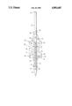
- FIGURE of the drawing illustrates a longitudinal schematic axial sectional view of an embodiment of the invention.
- the prepenetrator 11 of a projectile 10 has on its periphery 12 annular grooves (unevenesses) 2.1, . . . , 2.8 which are formed as fracture zones These annular grooves divide the prepenetrator into a plurality of sections 1.1, . . . , 1.8 of predetermined axial length which have an average exterior diameter d a .
- the (core) diameter d e .sbsb.1 . . . 8 increases with the increasing distance from the nose point 14; in this manner there is attained an intentional breakup or disintegration whereby the breaking or disintegration tendency decreases from the nose 14 to the tail region 24 as the distance therefrom increases.
- a transfer cone 21 adjoins the last annular groove 2.8.
- the largest exterior diameter of the transfer cone corresponds to d a whereas the smallest exterior diameter corresponds to d h which is equal the diameter of the main penetrator 22.
- the tail section of the main penetrator is only schematically illustrated by means of the tail region 24; therefore the stabilizing guides which are generally mounted on the outer periphery of the tail section are not illustrated.
- the length and smallest diameter d h of the transfer cone 21 are set at predetermined limits. It has been found that as largest diameter the diameter d a corresponding to the diameter of the main penetrator portion 11 is most suitable.
- a detachable sabot 40 having 4 segments 31 is coaxially mounted on the projectile. Only two of the four segments 31 have been illustrated for purposes of clarity.
- the sabot has a forwardly disposed flange 32 and a rearwardly disposed flange 34.
- the flanges 32 and 34 are respectively armed with guide rings or bands 38 and 40.
- the band 40 functions as a sealing band which is adjoined at its rear side by a rearwardly extending gas pressure receiving surface 42.
- An air pocket 46 is formed at the forward edge 44 of the sabot 30, which air pocket favors the separation of the sabot 30 from the projectile 10 due to the effect of the air barriers forming in front of the projectile after the projectile assembly has left the muzzle of the gun barrel.
- the segments 31 of the sabot 30 have interior unevenesses which have not been illustrated in detail.
- the unevenesses on the segments 31 interdigitate with unevenesses (annular grooves 2.3 to 2.8) on the periphery of the main penetrator portion 11 and a connection zone 16. This zone extends between a forward edge 18 and a rear edge 20, so that the transfer cone 21 is completely encompassed in the connection zone 16.
- the gas pressure receiving surface 42 is loaded after firing and during the firing process by means of the propellant gases which form during such firing process.
- the energy resulting from this firing process is, during the movement of the projectile assembly within the gun barrel, in view of the mutual form-locking in the connection zone 16, reliably transferred onto the projectile 10 proper.
- a firing strength due to the interaction between the transfer cone 21 with an inner peripheral surface 48 of the segments 31 (not illustrated in detail) which tightly interengage and thereby act as form-locking element, so as to substantially contribute in the illustrated form to the firing strength while assuring a large penetrator length.
- the penetrator material for example a heavy metal-sinter-alloy such as, for example, alloys having a tungsten basis respectively an enriched uranium basis.
- a heavy metal-sinter-alloy such as, for example, alloys having a tungsten basis respectively an enriched uranium basis.
- the core diameter d e .sbsb.1 . . . 8 and the length of the sections 1.1 . . . 1.8 but also the cross-sectional shapes of the unevenesses 2.1 . . . 2.8 may advantageously be varied in different ways thereby be adapted to a plurality of conditions determined by the target.
Landscapes
- Engineering & Computer Science (AREA)
- General Engineering & Computer Science (AREA)
- Chemical & Material Sciences (AREA)
- Combustion & Propulsion (AREA)
- Aiming, Guidance, Guns With A Light Source, Armor, Camouflage, And Targets (AREA)
- Orthopedics, Nursing, And Contraception (AREA)
- Agricultural Chemicals And Associated Chemicals (AREA)
- Soil Working Implements (AREA)
Abstract
Description
Claims (2)
Applications Claiming Priority (2)
| Application Number | Priority Date | Filing Date | Title |
|---|---|---|---|
| DE3031723 | 1980-08-23 | ||
| DE19803031723 DE3031723A1 (en) | 1980-03-27 | 1980-08-23 | Armour piercing shell with sub-calibre penetrator - has preset number of break-up points and spacing of distal break-up groove for coupling penetrator sections |
Publications (1)
| Publication Number | Publication Date |
|---|---|
| US4901645A true US4901645A (en) | 1990-02-20 |
Family
ID=6110206
Family Applications (1)
| Application Number | Title | Priority Date | Filing Date |
|---|---|---|---|
| US06/308,243 Expired - Fee Related US4901645A (en) | 1980-08-23 | 1981-08-24 | Inertial projectile having a breakable pre-penetrator |
Country Status (5)
| Country | Link |
|---|---|
| US (1) | US4901645A (en) |
| GB (1) | GB2207737B (en) |
| IT (1) | IT1209888B (en) |
| NL (1) | NL8103811A (en) |
| NO (1) | NO162738C (en) |
Cited By (12)
| Publication number | Priority date | Publication date | Assignee | Title |
|---|---|---|---|---|
| US5204494A (en) * | 1990-04-14 | 1993-04-20 | Rheinmetall Gmbh | Subcaliber projectile with sabot |
| US5313889A (en) * | 1993-01-04 | 1994-05-24 | The United States Of America As Represented By The Secretary Of The Army | Stabilization band/ring assembly for aligning a projectile in a gun tube |
| US5526752A (en) * | 1994-09-06 | 1996-06-18 | Rockwell International Corporation | Weapon for destruction of deeply buried and hardened targets |
| EP0825412A2 (en) | 1996-08-19 | 1998-02-25 | Lockheed Martin Corporation | Penetrator having multiple impact segments |
| EP0892241A2 (en) | 1997-07-18 | 1999-01-20 | Lockheed Martin Corporation | Penetrator having multiple impact segments |
| EP0898145A2 (en) | 1997-08-21 | 1999-02-24 | Lockheed Martin Corporation | Penetrator having multiple impact segments, including an explosive segment |
| US20040055501A1 (en) * | 2002-09-20 | 2004-03-25 | Hunn David L. | Penetrator and method for using same |
| US20040055502A1 (en) * | 2002-09-20 | 2004-03-25 | Lockheed Martin Corporation | Penetrator and method for using same |
| WO2004027341A1 (en) * | 2002-09-20 | 2004-04-01 | Lockheed Martin Corporation | A penetrator and method for using same |
| US7448324B1 (en) * | 2006-05-03 | 2008-11-11 | At&T Intellectual Property Ii, L.P. | Segmented rod projectile |
| US9746298B2 (en) * | 2014-07-30 | 2017-08-29 | The United States Of America As Represented By The Secretary Of The Army | Flechette for direct fire weapons |
| US20180224251A1 (en) * | 2015-10-06 | 2018-08-09 | Rheinmetall Waffe Munition Gmbh | Penetrator and sub-caliber projectile |
Families Citing this family (1)
| Publication number | Priority date | Publication date | Assignee | Title |
|---|---|---|---|---|
| FR2740213B1 (en) * | 1995-10-19 | 1997-12-05 | France Etat | ARROW-TYPE KINETIC ENERGY PROJECTILE |
Citations (7)
| Publication number | Priority date | Publication date | Assignee | Title |
|---|---|---|---|---|
| US90732A (en) * | 1869-06-01 | Improvement in projectiles | ||
| US3148472A (en) * | 1962-06-11 | 1964-09-15 | Edward N Hegge | Subcaliber projectile and sabot for high velocity firearms |
| US3899978A (en) * | 1972-07-22 | 1975-08-19 | Rheinmetall Gmbh | Fin-stabilized subcaliber projectile |
| US3977324A (en) * | 1964-01-13 | 1976-08-31 | The United States Of America As Represented By The Secretary Of The Army | Sabotless micro projectile |
| US4108072A (en) * | 1964-12-29 | 1978-08-22 | Deutsch-Franzosisches Forschungsinstitut | Armor-piercing projectile having spaced cores |
| US4281599A (en) * | 1978-06-06 | 1981-08-04 | Diehl Gmbh & Co. | Projectile |
| US4362107A (en) * | 1978-10-14 | 1982-12-07 | Rheinmetall Gmbh | Practice projectile |
-
1981
- 1981-08-13 NL NL8103811A patent/NL8103811A/en not_active Application Discontinuation
- 1981-08-13 IT IT8149100A patent/IT1209888B/en active
- 1981-08-19 GB GB8125292A patent/GB2207737B/en not_active Expired
- 1981-08-21 NO NO812833A patent/NO162738C/en unknown
- 1981-08-24 US US06/308,243 patent/US4901645A/en not_active Expired - Fee Related
Patent Citations (7)
| Publication number | Priority date | Publication date | Assignee | Title |
|---|---|---|---|---|
| US90732A (en) * | 1869-06-01 | Improvement in projectiles | ||
| US3148472A (en) * | 1962-06-11 | 1964-09-15 | Edward N Hegge | Subcaliber projectile and sabot for high velocity firearms |
| US3977324A (en) * | 1964-01-13 | 1976-08-31 | The United States Of America As Represented By The Secretary Of The Army | Sabotless micro projectile |
| US4108072A (en) * | 1964-12-29 | 1978-08-22 | Deutsch-Franzosisches Forschungsinstitut | Armor-piercing projectile having spaced cores |
| US3899978A (en) * | 1972-07-22 | 1975-08-19 | Rheinmetall Gmbh | Fin-stabilized subcaliber projectile |
| US4281599A (en) * | 1978-06-06 | 1981-08-04 | Diehl Gmbh & Co. | Projectile |
| US4362107A (en) * | 1978-10-14 | 1982-12-07 | Rheinmetall Gmbh | Practice projectile |
Cited By (17)
| Publication number | Priority date | Publication date | Assignee | Title |
|---|---|---|---|---|
| US5204494A (en) * | 1990-04-14 | 1993-04-20 | Rheinmetall Gmbh | Subcaliber projectile with sabot |
| US5313889A (en) * | 1993-01-04 | 1994-05-24 | The United States Of America As Represented By The Secretary Of The Army | Stabilization band/ring assembly for aligning a projectile in a gun tube |
| US5526752A (en) * | 1994-09-06 | 1996-06-18 | Rockwell International Corporation | Weapon for destruction of deeply buried and hardened targets |
| EP0825412A2 (en) | 1996-08-19 | 1998-02-25 | Lockheed Martin Corporation | Penetrator having multiple impact segments |
| US5834684A (en) * | 1996-08-19 | 1998-11-10 | Lockheed Martin Vought Systems Corporation | Penetrator having multiple impact segments |
| US6021716A (en) * | 1997-07-18 | 2000-02-08 | Lockheed Martin Corporation | Penetrator having multiple impact segments |
| EP0892241A2 (en) | 1997-07-18 | 1999-01-20 | Lockheed Martin Corporation | Penetrator having multiple impact segments |
| EP0898145A2 (en) | 1997-08-21 | 1999-02-24 | Lockheed Martin Corporation | Penetrator having multiple impact segments, including an explosive segment |
| US5988071A (en) * | 1997-08-21 | 1999-11-23 | Lockheed Martin Corporation | Penetrator having multiple impact segments, including an explosive segment |
| US20040055501A1 (en) * | 2002-09-20 | 2004-03-25 | Hunn David L. | Penetrator and method for using same |
| US20040055502A1 (en) * | 2002-09-20 | 2004-03-25 | Lockheed Martin Corporation | Penetrator and method for using same |
| WO2004027341A1 (en) * | 2002-09-20 | 2004-04-01 | Lockheed Martin Corporation | A penetrator and method for using same |
| US6843179B2 (en) | 2002-09-20 | 2005-01-18 | Lockheed Martin Corporation | Penetrator and method for using same |
| US7448324B1 (en) * | 2006-05-03 | 2008-11-11 | At&T Intellectual Property Ii, L.P. | Segmented rod projectile |
| US9746298B2 (en) * | 2014-07-30 | 2017-08-29 | The United States Of America As Represented By The Secretary Of The Army | Flechette for direct fire weapons |
| US20180224251A1 (en) * | 2015-10-06 | 2018-08-09 | Rheinmetall Waffe Munition Gmbh | Penetrator and sub-caliber projectile |
| US11320246B2 (en) * | 2015-10-06 | 2022-05-03 | Rheinmetall Waffe Munition Gmbh | Penetrator and sub-caliber projectile |
Also Published As
| Publication number | Publication date |
|---|---|
| GB2207737A (en) | 1989-02-08 |
| GB2207737B (en) | 1989-06-28 |
| IT1209888B (en) | 1989-08-30 |
| NO812833L (en) | 1988-10-06 |
| IT8149100A0 (en) | 1981-08-13 |
| NO162738C (en) | 1990-02-07 |
| NO162738B (en) | 1989-10-30 |
| NL8103811A (en) | 1989-01-02 |
Similar Documents
| Publication | Publication Date | Title |
|---|---|---|
| US3714900A (en) | Discarding sabot projectiles | |
| US5675107A (en) | Muzzle brake for medium or large caliber cannons | |
| US3507221A (en) | Armor piercing,sabot shells | |
| US3905299A (en) | Discarding sabot projectiles | |
| US4901645A (en) | Inertial projectile having a breakable pre-penetrator | |
| US3446147A (en) | Casing for the sabot of a projectile | |
| US4648323A (en) | Fragmentation munition | |
| US4706569A (en) | Armor breaking projectile | |
| US3762332A (en) | Projectile sabot | |
| US2288604A (en) | Projectile | |
| US4932326A (en) | Fiercing projectiles | |
| JP6499649B2 (en) | Bullets for small or light weapons with projectile body | |
| US6237497B1 (en) | Spin-stabilized artillery projectile having gas pressure equalizing means | |
| US3956990A (en) | Beehive projectile | |
| US4612859A (en) | Multiple purpose warhead | |
| US4597333A (en) | Two-part armor-piercing projectile | |
| US4029018A (en) | Sabot for subcalibre projectile | |
| GB2208247A (en) | Fin-stabilized, discarding-sabot projectile | |
| US5063855A (en) | Projectile arrangement | |
| US3952657A (en) | Rifle cartridge | |
| US3247795A (en) | Spinning projectile for smooth bore guns | |
| US5081931A (en) | Spin stabilized carrier projectile provided with a metal driving band | |
| US4773331A (en) | Connection arrangement between a sabot jacket and the sabot rear portion of a sabot projectile | |
| WO2019084164A1 (en) | Cartridge | |
| US6662726B1 (en) | Kinetic energy penetrator |
Legal Events
| Date | Code | Title | Description |
|---|---|---|---|
| AS | Assignment |
Owner name: RHEINMETALL GMBH, ULMENSTR. 125 4 DUESSELDORF, W-G Free format text: ASSIGNMENT OF ASSIGNORS INTEREST.;ASSIGNORS:BISPING, BERNHARD;JANSEN, HERMANN;WALLOW, PETER;REEL/FRAME:003936/0270 Effective date: 19810824 Owner name: RHEINMETALL GMBH, GERMANY Free format text: ASSIGNMENT OF ASSIGNORS INTEREST;ASSIGNORS:BISPING, BERNHARD;JANSEN, HERMANN;WALLOW, PETER;REEL/FRAME:003936/0270 Effective date: 19810824 |
|
| REMI | Maintenance fee reminder mailed | ||
| LAPS | Lapse for failure to pay maintenance fees | ||
| FP | Lapsed due to failure to pay maintenance fee |
Effective date: 19930220 |
|
| STCH | Information on status: patent discontinuation |
Free format text: PATENT EXPIRED DUE TO NONPAYMENT OF MAINTENANCE FEES UNDER 37 CFR 1.362 |