US4901643A - Pyrotechnic fuze for projectiles - Google Patents
Pyrotechnic fuze for projectiles Download PDFInfo
- Publication number
- US4901643A US4901643A US07/277,275 US27727588A US4901643A US 4901643 A US4901643 A US 4901643A US 27727588 A US27727588 A US 27727588A US 4901643 A US4901643 A US 4901643A
- Authority
- US
- United States
- Prior art keywords
- slider
- delay
- pyrotechnic
- detonator
- composition
- Prior art date
- Legal status (The legal status is an assumption and is not a legal conclusion. Google has not performed a legal analysis and makes no representation as to the accuracy of the status listed.)
- Expired - Fee Related
Links
- 239000000203 mixture Substances 0.000 claims abstract description 34
- 239000002360 explosive Substances 0.000 claims abstract description 6
- 235000015842 Hesperis Nutrition 0.000 claims abstract description 3
- 235000012633 Iberis amara Nutrition 0.000 claims abstract description 3
- 238000009434 installation Methods 0.000 claims description 9
- 238000010304 firing Methods 0.000 claims description 4
- 230000005540 biological transmission Effects 0.000 description 7
- 238000002485 combustion reaction Methods 0.000 description 4
- 239000002184 metal Substances 0.000 description 3
- 230000005484 gravity Effects 0.000 description 2
- 239000000470 constituent Substances 0.000 description 1
- 230000001419 dependent effect Effects 0.000 description 1
- 230000000694 effects Effects 0.000 description 1
- 239000007789 gas Substances 0.000 description 1
- 230000000977 initiatory effect Effects 0.000 description 1
- 230000007257 malfunction Effects 0.000 description 1
- 238000012986 modification Methods 0.000 description 1
- 230000004048 modification Effects 0.000 description 1
- 239000002245 particle Substances 0.000 description 1
- 238000000926 separation method Methods 0.000 description 1
- 230000000087 stabilizing effect Effects 0.000 description 1
- 230000001960 triggered effect Effects 0.000 description 1
Images
Classifications
-
- F—MECHANICAL ENGINEERING; LIGHTING; HEATING; WEAPONS; BLASTING
- F42—AMMUNITION; BLASTING
- F42C—AMMUNITION FUZES; ARMING OR SAFETY MEANS THEREFOR
- F42C9/00—Time fuzes; Combined time and percussion or pressure-actuated fuzes; Fuzes for timed self-destruction of ammunition
- F42C9/14—Double fuzes; Multiple fuzes
- F42C9/142—Double fuzes; Multiple fuzes combined time and percussion fuzes in which the timing is caused by combustion
-
- F—MECHANICAL ENGINEERING; LIGHTING; HEATING; WEAPONS; BLASTING
- F42—AMMUNITION; BLASTING
- F42C—AMMUNITION FUZES; ARMING OR SAFETY MEANS THEREFOR
- F42C15/00—Arming-means in fuzes; Safety means for preventing premature detonation of fuzes or charges
- F42C15/18—Arming-means in fuzes; Safety means for preventing premature detonation of fuzes or charges wherein a carrier for an element of the pyrotechnic or explosive train is moved
- F42C15/184—Arming-means in fuzes; Safety means for preventing premature detonation of fuzes or charges wherein a carrier for an element of the pyrotechnic or explosive train is moved using a slidable carrier
Definitions
- the present invention relates to a pyrotechnic fuze for projectiles, rockets, bomblets and mines, which is basically a pyrotechnic self-destruct device, in which a triggering device for a pyrotechnic delay arrangement is arranged within a housing, the triggering device consisting of an igniting composition and a delay composition, a detonator for the triggering of an explosive charge and a striker for the detonator, whereby the detonator is arranged in a transversely movable slider.
- the housing includes a side or lateral opening for the slider which is outwardly displaceable beyond the external contour of the housing, and which slider contains the delay installation.
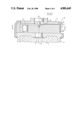
- FIG. 1 illustrates a fragmentary sectional view of a pyrotechnic fuze for a bomblet
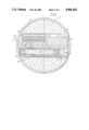
- FIG. 2 illustrates a sectional view taken along line II--II in FIG. 1;
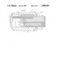
- FIG. 3 illustrates the fuze of FIG. 2 in its armed position
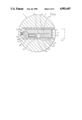
- FIG. 4 illustrates a sectional view through a further embodiment of a fuze.
- a bomblet 1 which includes a transmission charge 2 and an explosive charge 3, supports a housing 4 for a pyrotechnic fuze 5.
- a casing or jacket 6 possessing an aperture 7 for a slider 8 connects the housing 4 with the bomblet 1.
- a striker 15 engages into a bore 16 in the slider 8 in the secured position.
- a detonator 17 and a sheet metal plate 18 with a primer or firing pin 19 are flanged into the slider 8.
- a delay detonator 25 possesses the following constituents:
- the last-mentioned, in the secured position pursuant to FIG. 2, is located outside of the range of response 32 for the detonator 17.
- the small tube 26 is displaceably supported in a sliding guide 34.
- a ball or spheroid 35 in the secured position of the slider 8, is supported in an aperture 36 of the slider 8.
- the ball 35 is supported against the sliding guide 34 and contacts against a shoulder 37 on the delay detonator 25.
- the aperture 36 is located outside of the housing 4.
- the slider 8 is equipped with a spring 40.
- the slider 8 possesses a center of gravity 9 at a distance 10 from the main axis 11.
- the slider during its phase of movement, will initially only convey the delay detonator 25 up to the contacting of the stop 21 against the stop 20 on the housing 4. Thereby, the delay detonator 25 is armed. Through the impact, the inertial forces act alone on the delay detonator 25, and move the latter against the sheet metal plate 18. After the passage of the combustion period of the delay composition 30, it triggers the transmission composition 31 of the detonator 17 which is located immediately adjacent the detonator 17, in conformance with the arrow 44. This then initiates the explosive charge 3 through the transmission charge 2. In the armed position (FIG. 3) the slider 8 is secured in a known manner.
- the described operative sequence is effected only under the prerequisite that the bomblet 1 strikes against soft ground, so that no corresponding impulse is encountered for the striker 15.
- the capability of telescoping for the delay detonator facilitates the provision of a relatively extensive constructional length, which is only limited by the extent of the approach path 50 between the primer or firing pin 19 and the triggering composition. Moreover, in the secured position, there is also present a distance or spacing which serves for ensuring safety, which is defined as the response zone 32.
- the delay detonator 25 is triggered in the secured position, this will afford that the detonator will not be activated due to the spatial separation.
- the transmission composition 31 is positioned in immediate proximity to the detonator 17.
- the transmission composition 31 penetrates the segment 28, the wall 33 and the detonator cup 38.
- a spring 12 causes, or supports, the arming of the delay detonator 25.
- a slider 68 with the eccentric center of gravity 69 is fixed in the secured position through the striker 65 which cooperates with the detonator upon the impact of the bomblet 1, as shown in FIG. 1.
- the ball 35 secures the striker bolt 65.
- the latter lies against the guidance 61.
- the guidance 61 and the housing 4 are provided with a cutout 14.
- the centrifugal forces move the slider 68 into the position 72 which is secured in a known manner.
- the ball 35 falls into the cutout 14 and thereby releases the striker bolt 65, which triggers the triggering composition 29. After the pregiven combustion period of the delay composition 70, the latter triggers the detonator 17. This detonator then initiates the explosive charge (not shown) of the bomblet 1.
- the extensive constructional length of the delay composition 70 by means of which there can be realized the relatively extremely lengthy combustion periods.
- the easy and readily surveillable manipulatability of the slider 68 is imparted thereto by the integrated units which have already been described with regard to FIG. 3; in essence, namely the striker bolt 65, pyrotechnic delay device and detonator 17.
- a spring 66 causes the arming of the slider 68 inclusive of the triggering function of the striker bolt 65.
Landscapes
- Engineering & Computer Science (AREA)
- General Engineering & Computer Science (AREA)
- Air Bags (AREA)
Abstract
A pyrotechnic fuze for projectiles, rockets, bomblets and mines, which is basically a pyrotechnic self-destruct device, in which a triggering device for a pyrotechnic delay arrangement is arranged within a housing. The triggering device consists of an igniting composition and a delay composition, a detonator for the triggering of an explosive charge and a striker for the detonator, whereby the detonator is arranged in a transversely movable slider.
Description
1. Field of the Invention
The present invention relates to a pyrotechnic fuze for projectiles, rockets, bomblets and mines, which is basically a pyrotechnic self-destruct device, in which a triggering device for a pyrotechnic delay arrangement is arranged within a housing, the triggering device consisting of an igniting composition and a delay composition, a detonator for the triggering of an explosive charge and a striker for the detonator, whereby the detonator is arranged in a transversely movable slider.
2. Discussion of the Prior Art
In a fuze for bomblets pursuant to the disclosure of German Patent No. 33 33 312, in a transversely movable slider there is provided a detonator and an igniting composition for a spirally-shaped delay composition which is fixed to a housing. It has been recognized that malfunctions can occur with spirally-extending delay composition; for instance, the front of combustion for the pyrotechnic composition will terminate prematurely. In order to overcome this disadvantage, there are employed straight or, in effect, extended incendiary compositions. In this instance a, disadvantage for the delay composition arranged so as to extend transversely of the main axis of the ammunition, is the relatively short constructional length. The constructional length of the incendiary composition is dependent upon the caliber of the ammunition.
Accordingly, it is an object of the present invention to provide a pyrotechnic fuze which allows for the greatest possible constructional length for the delay composition at an assured triggering of the detonator.
The foregoing object is achieved in a pyrotechnic fuze, as described hereinabove, in that the housing includes a side or lateral opening for the slider which is outwardly displaceable beyond the external contour of the housing, and which slider contains the delay installation.
Further features and modifications of the invention may now be readily ascertained from the following detailed description of an exemplary embodiment as described hereinabove, taken in conjunction with the accompanying drawings; in which:
FIG. 1 illustrates a fragmentary sectional view of a pyrotechnic fuze for a bomblet;
FIG. 2 illustrates a sectional view taken along line II--II in FIG. 1;
FIG. 3 illustrates the fuze of FIG. 2 in its armed position; and
FIG. 4 illustrates a sectional view through a further embodiment of a fuze.
A bomblet 1 which includes a transmission charge 2 and an explosive charge 3, supports a housing 4 for a pyrotechnic fuze 5. A casing or jacket 6 possessing an aperture 7 for a slider 8 connects the housing 4 with the bomblet 1.
A striker 15 engages into a bore 16 in the slider 8 in the secured position. A detonator 17 and a sheet metal plate 18 with a primer or firing pin 19 are flanged into the slider 8.
As seen in FIG. 2, a delay detonator 25 possesses the following constituents:
A small tube 27 with the segments 27 and 28, an initiating composition 29, a delay composition 30 and a transmission composition 31. The last-mentioned, in the secured position pursuant to FIG. 2, is located outside of the range of response 32 for the detonator 17. The small tube 26 is displaceably supported in a sliding guide 34. A ball or spheroid 35 in the secured position of the slider 8, is supported in an aperture 36 of the slider 8. The ball 35 is supported against the sliding guide 34 and contacts against a shoulder 37 on the delay detonator 25. In the armed position of the slider 8, the aperture 36 is located outside of the housing 4. The slider 8 is equipped with a spring 40. The slider 8 possesses a center of gravity 9 at a distance 10 from the main axis 11.
The bomblet 1 which is ejected from a spin-stabilized projectile also possesses a corresponding spin. A stabilizing parachute raises the striker 19 out of the bore 16 in a known manner. Thereafter, due to the centrifugal forces which are generated through the intermediary of the spin, and which forces are effective on the slider 8, and supported by the spring 40, these forces raise the slider 8 into the armed position as ascertainable in FIG. 3. As soon as the aperture is located outside of the casing or jacket 6, the ball 35 is slung out of the opening or aperture 36, and as a result, releases the delay detonator 25. The latter, due to the inertial forces, strikes against the sheet metal plate 18, as a result of which the firing pin or primer 19 initiates the triggering composition 29. It is important that the slider, during its phase of movement, will initially only convey the delay detonator 25 up to the contacting of the stop 21 against the stop 20 on the housing 4. Thereby, the delay detonator 25 is armed. Through the impact, the inertial forces act alone on the delay detonator 25, and move the latter against the sheet metal plate 18. After the passage of the combustion period of the delay composition 30, it triggers the transmission composition 31 of the detonator 17 which is located immediately adjacent the detonator 17, in conformance with the arrow 44. This then initiates the explosive charge 3 through the transmission charge 2. In the armed position (FIG. 3) the slider 8 is secured in a known manner.
The described operative sequence is effected only under the prerequisite that the bomblet 1 strikes against soft ground, so that no corresponding impulse is encountered for the striker 15.
The capability of telescoping for the delay detonator facilitates the provision of a relatively extensive constructional length, which is only limited by the extent of the approach path 50 between the primer or firing pin 19 and the triggering composition. Moreover, in the secured position, there is also present a distance or spacing which serves for ensuring safety, which is defined as the response zone 32. Hereby, when outside of the rule, the delay detonator 25 is triggered in the secured position, this will afford that the detonator will not be activated due to the spatial separation.
The hot gases and particles from the transmission composition 31 are conducted off in a discharge spaces (not shown) of the pyrotechnic fuze 5 (not shown).
Notwithstanding the capability of telescoping for the delay detonator 25, in the armed position it is afforded that the transmission composition 31 is positioned in immediate proximity to the detonator 17. The transmission composition 31 penetrates the segment 28, the wall 33 and the detonator cup 38.
For a bomblet without spin, a spring 12 causes, or supports, the arming of the delay detonator 25.
Pursuant to FIG. 4, a slider 68 with the eccentric center of gravity 69 is fixed in the secured position through the striker 65 which cooperates with the detonator upon the impact of the bomblet 1, as shown in FIG. 1.
The slider 68 is displaceably supported in the housing 4 intermediate guide rails 61. The housing 4 possesses a single aperture 7 for the slider 68.
In the slider 68 there are arranged the following components:
the detonator 17, two bores 62, 63 with the connector 64, a spring-actuated striker bolt 65, the triggering composition 29 and a U-shaped delay composition 70 of a pyrotechnic delay device 60 with a plate 71.
The ball 35 secures the striker bolt 65. The latter lies against the guidance 61. The guidance 61 and the housing 4 are provided with a cutout 14.
The function is as follows:
When a bomblet 1 which possesses a spin is in free-flight, and the striker bolt 65 has been retracted, then the pyrotechnic self-destruct device is set into operation as follows:
The centrifugal forces move the slider 68 into the position 72 which is secured in a known manner.
The ball 35 falls into the cutout 14 and thereby releases the striker bolt 65, which triggers the triggering composition 29. After the pregiven combustion period of the delay composition 70, the latter triggers the detonator 17. This detonator then initiates the explosive charge (not shown) of the bomblet 1.
Advantageous is the extensive constructional length of the delay composition 70 by means of which there can be realized the relatively extremely lengthy combustion periods. The easy and readily surveillable manipulatability of the slider 68 is imparted thereto by the integrated units which have already been described with regard to FIG. 3; in essence, namely the striker bolt 65, pyrotechnic delay device and detonator 17.
In a bomblet without any spin, a spring 66 causes the arming of the slider 68 inclusive of the triggering function of the striker bolt 65.
Claims (6)
1. A pyrotechnic self-destruct fuze for projectiles, rockets, bomblets and mines, comprising a housing; triggering means for a pyrotechnic delay installation in said housing consisting of a triggering composition in a delay composition; a detonator for the triggering of an explosive charge and a striker for the detonator, said detonator being arranged in a transversely movable slider, and said housing having a side aperture for the slider which is displaceable outwardly beyond the external housing contour, and which slider contains the delay installation; wherein the slider includes two bores which extend parallel and which are only connected in a U-shape at one end of the slider in the plane of movement of the slider, said bores containing the triggering means and the pyrotechnic delay installation.
2. A pyrotechnic self-destruct fuze as claimed in claim 1, wherein the delay installation in the slider is supported so as to be longitudinally displaceable; securing means for fastening the delay installation in the slider and unlatching the installation in only the armed position of the slider, and said slider includes a stationary firing pin for said displaceable delay installation.
3. A pyrotechnic self-destruct fuze as claimed in claim 1, wherein the securing means for the delay installation includes a ball latch, the ball in the secured position of the slider being supported in an aperture of the slider, and the slider is supported through a sliding guide and a shoulder when the aperture is proximate the contour of the housing.
4. A pyrotechnic self-destruct fuze as claimed in claim 1, wherein a narrow tube includes a transfer composition, a delay composition and a detonative triggering composition, said transfer composition in the secured position being located outside of the region of response for the detonator.
5. A pyrotechnic self-destruct fuze as claimed in claim 1, wherein the slider is fixed through spring force or through centrifugal force in a secured position through a form-fitted striker means which is supported in the main axis of the fuze, and the slider is movable subsequent to unlatching from a safe position into an armed position.
6. A pyrotechnic self-destruct fuze as claimed in claim 1, wherein the pyrotechnic delay composition is constructed U-shaped and the free end thereof contacts the detonator in the slider at generally the end surface thereof.
Applications Claiming Priority (2)
| Application Number | Priority Date | Filing Date | Title |
|---|---|---|---|
| DE3740967 | 1987-12-03 | ||
| DE19873740967 DE3740967A1 (en) | 1987-12-03 | 1987-12-03 | PYROTECHNICAL IGNITION FOR BULLETS |
Publications (1)
| Publication Number | Publication Date |
|---|---|
| US4901643A true US4901643A (en) | 1990-02-20 |
Family
ID=6341802
Family Applications (1)
| Application Number | Title | Priority Date | Filing Date |
|---|---|---|---|
| US07/277,275 Expired - Fee Related US4901643A (en) | 1987-12-03 | 1988-11-29 | Pyrotechnic fuze for projectiles |
Country Status (3)
| Country | Link |
|---|---|
| US (1) | US4901643A (en) |
| EP (1) | EP0318995B1 (en) |
| DE (2) | DE3740967A1 (en) |
Cited By (7)
| Publication number | Priority date | Publication date | Assignee | Title |
|---|---|---|---|---|
| US4998476A (en) * | 1989-04-18 | 1991-03-12 | Diehl Gmbh & Co. | Fuze for a bomblet |
| US5375526A (en) * | 1993-02-04 | 1994-12-27 | Rheinmetall Gmbh | Fuze mechanism for projectiles, rockets, bomblets and mines having a pyrotechnic self-destruct mechanism |
| US5576510A (en) * | 1994-12-01 | 1996-11-19 | Gebruder Junghans Gmbh | Percussion fuse for ammunition |
| US6318270B1 (en) * | 1999-06-30 | 2001-11-20 | Rheinmetall W & M Gmbh | Safety element particularly for a fuze of a substantially non-spinning projectile |
| ES2161580A1 (en) * | 1997-06-25 | 2001-12-01 | Rheinmetall W & M Gmbh | Igniter for spinning projectile used in munitions |
| ES2174661A1 (en) * | 1999-02-22 | 2002-11-01 | Instalaza Sa | Improvements in self-destructing electronic fuses. |
| CN109654961A (en) * | 2018-12-10 | 2019-04-19 | 中国航天科工集团八五研究所 | It is a kind of can effectively anti-sticking thorax safety ignitor |
Families Citing this family (6)
| Publication number | Priority date | Publication date | Assignee | Title |
|---|---|---|---|---|
| DE3925235A1 (en) * | 1989-07-29 | 1991-01-31 | Rheinmetall Gmbh | BOMBLETZUENDER |
| AT403410B (en) * | 1994-01-31 | 1998-02-25 | Oregon Ets Patentverwertung | IGNITION FOR A GRENADE |
| FR2737293B1 (en) * | 1995-07-27 | 1997-10-17 | Giat Ind Sa | SYSTEM FOR GENERATING THE EXPLOSIVE LOAD OF A SUBMUNITION ON BOARD IN A CARRIER |
| DE19919001A1 (en) * | 1999-04-27 | 2000-11-09 | Junghans Gmbh Geb | Pyrotechnic self-dismantling for ammunition |
| DE102012006429B4 (en) * | 2012-03-30 | 2013-11-07 | Diehl Bgt Defence Gmbh & Co. Kg | Device for igniting a pyrotechnic active mass |
| EP3076122B1 (en) * | 2015-04-01 | 2018-10-24 | Inauen-Schätti AG | System for triggering of avalanches |
Citations (4)
| Publication number | Priority date | Publication date | Assignee | Title |
|---|---|---|---|---|
| US4029016A (en) * | 1976-06-29 | 1977-06-14 | The United States Of America As Represented By The Secretary Of The Army | Plural mode fuze |
| US4030418A (en) * | 1975-10-30 | 1977-06-21 | The United States Of America As Represented By The Secretary Of The Army | Gravity deployed mine with combined upper clearing charge firing and delayed main charge initiation |
| DE3333312A1 (en) * | 1983-09-15 | 1985-04-04 | Rheinmetall GmbH, 4000 Düsseldorf | IGNITION FOR A SUBFLOOR |
| US4765245A (en) * | 1984-12-03 | 1988-08-23 | Her Majesty The Queen In Right Of Canada | Firing pin and safety and arming mechanism for a penetrating warhead |
Family Cites Families (10)
| Publication number | Priority date | Publication date | Assignee | Title |
|---|---|---|---|---|
| GB529505A (en) * | 1938-02-17 | 1940-11-22 | Bofors Ab | Percussion fuzes for aerial bombs |
| GB624135A (en) * | 1945-02-02 | 1949-05-27 | Controles Ind Et | Improvements in and relating to detonating devices for rocket projectiles |
| US3025795A (en) * | 1958-02-12 | 1962-03-20 | Thiokol Chemical Corp | Time delay fuse element |
| CH456403A (en) * | 1966-07-28 | 1968-07-31 | Tamerlan Ets | Percussion fuze for projectile |
| CH448812A (en) * | 1967-03-10 | 1967-12-15 | Fibora Ag | Mine detonator with detonator fuse |
| DE3539279A1 (en) * | 1985-11-06 | 1987-05-07 | Diehl Gmbh & Co | Detonator for a parachute-stabilised or strip-stabilised submunition |
| FR2592475B1 (en) * | 1985-12-27 | 1989-11-03 | Lacroix E Tous Artifices | PYROTECHNICALLY ACTUATED LOAD AND AMMUNITION INCORPORATING THE SAME. |
| DE8614108U1 (en) * | 1986-05-24 | 1987-09-24 | Diehl GmbH & Co, 8500 Nürnberg | Impact fuse of an infantry grenade |
| DE3624713C2 (en) * | 1986-07-22 | 1995-09-07 | Diehl Gmbh & Co | Impact detonator with self-dismantling device for a bomblet |
| IL82066A (en) * | 1987-03-31 | 1992-03-29 | Israel State | Fuse for sub-munition warhead |
-
1987
- 1987-12-03 DE DE19873740967 patent/DE3740967A1/en not_active Withdrawn
-
1988
- 1988-11-29 US US07/277,275 patent/US4901643A/en not_active Expired - Fee Related
- 1988-12-01 EP EP88120077A patent/EP0318995B1/en not_active Expired - Lifetime
- 1988-12-01 DE DE3889636T patent/DE3889636D1/en not_active Expired - Fee Related
Patent Citations (4)
| Publication number | Priority date | Publication date | Assignee | Title |
|---|---|---|---|---|
| US4030418A (en) * | 1975-10-30 | 1977-06-21 | The United States Of America As Represented By The Secretary Of The Army | Gravity deployed mine with combined upper clearing charge firing and delayed main charge initiation |
| US4029016A (en) * | 1976-06-29 | 1977-06-14 | The United States Of America As Represented By The Secretary Of The Army | Plural mode fuze |
| DE3333312A1 (en) * | 1983-09-15 | 1985-04-04 | Rheinmetall GmbH, 4000 Düsseldorf | IGNITION FOR A SUBFLOOR |
| US4765245A (en) * | 1984-12-03 | 1988-08-23 | Her Majesty The Queen In Right Of Canada | Firing pin and safety and arming mechanism for a penetrating warhead |
Cited By (8)
| Publication number | Priority date | Publication date | Assignee | Title |
|---|---|---|---|---|
| US4998476A (en) * | 1989-04-18 | 1991-03-12 | Diehl Gmbh & Co. | Fuze for a bomblet |
| US5375526A (en) * | 1993-02-04 | 1994-12-27 | Rheinmetall Gmbh | Fuze mechanism for projectiles, rockets, bomblets and mines having a pyrotechnic self-destruct mechanism |
| US5576510A (en) * | 1994-12-01 | 1996-11-19 | Gebruder Junghans Gmbh | Percussion fuse for ammunition |
| ES2161580A1 (en) * | 1997-06-25 | 2001-12-01 | Rheinmetall W & M Gmbh | Igniter for spinning projectile used in munitions |
| ES2174661A1 (en) * | 1999-02-22 | 2002-11-01 | Instalaza Sa | Improvements in self-destructing electronic fuses. |
| ES2174661B1 (en) * | 1999-02-22 | 2004-08-16 | Instalaza, S.A. | IMPROVEMENTS INTRODUCED IN SELF-DESTRUCTIVE ELECTRONIC SPOOLS. |
| US6318270B1 (en) * | 1999-06-30 | 2001-11-20 | Rheinmetall W & M Gmbh | Safety element particularly for a fuze of a substantially non-spinning projectile |
| CN109654961A (en) * | 2018-12-10 | 2019-04-19 | 中国航天科工集团八五研究所 | It is a kind of can effectively anti-sticking thorax safety ignitor |
Also Published As
| Publication number | Publication date |
|---|---|
| DE3889636D1 (en) | 1994-06-23 |
| EP0318995A2 (en) | 1989-06-07 |
| EP0318995A3 (en) | 1990-04-18 |
| DE3740967A1 (en) | 1989-06-15 |
| EP0318995B1 (en) | 1994-05-18 |
Similar Documents
| Publication | Publication Date | Title |
|---|---|---|
| US4811664A (en) | Fuse for sub-munition warhead | |
| US6622629B2 (en) | Submunition fuzing and self-destruct using MEMS arm fire and safe and arm devices | |
| US4901643A (en) | Pyrotechnic fuze for projectiles | |
| US4762066A (en) | Fuze for a parachute-stabilized or band-stabilized small bomb which rotates during flight | |
| US3913483A (en) | Grenade with fuze | |
| US2838999A (en) | Sensitive fuses | |
| US3425353A (en) | Arming and safety mechanism for a drag chute retarded bomb | |
| US4770096A (en) | Safing and arming mechanism | |
| US3410214A (en) | Percussion fuze | |
| US2705921A (en) | Fuze for non-rotating shaped charge projectiles | |
| US4873927A (en) | Pyrotechnic fuze for projectiles, rockets, bomblets and mines | |
| US4691634A (en) | Electro-explosive safety and arming device | |
| GB977022A (en) | Improvements relating to fuzes for projectiles | |
| RU2135950C1 (en) | Mechanical base fuze | |
| US5046424A (en) | Fuze for a bomblet projectile | |
| US6035783A (en) | High performance fuze | |
| US5375526A (en) | Fuze mechanism for projectiles, rockets, bomblets and mines having a pyrotechnic self-destruct mechanism | |
| US6481355B2 (en) | Bomblet fuze with self-destruct mechanism | |
| US3786754A (en) | Firing delay for point detonating fuze | |
| US4667600A (en) | Safe/arm explosive transfer mechanism | |
| NO170700B (en) | HULLADNINGSPROSJEKTIL | |
| US3435767A (en) | Safety device for a projectile | |
| US4693180A (en) | Impact detonator with a detonator cap | |
| US2934019A (en) | Fuze assembly | |
| US3945324A (en) | Projectile fuse |
Legal Events
| Date | Code | Title | Description |
|---|---|---|---|
| AS | Assignment |
Owner name: DIEHL GMBH & CO., A CORP. OF WEST GERMANY, GERMANY Free format text: ASSIGNMENT OF ASSIGNORS INTEREST.;ASSIGNORS:RUDENAUER, WERNER;MULLER, FRITZ;LIEBL, NORBERT;AND OTHERS;REEL/FRAME:005001/0680 Effective date: 19880711 |
|
| REMI | Maintenance fee reminder mailed | ||
| LAPS | Lapse for failure to pay maintenance fees | ||
| FP | Lapsed due to failure to pay maintenance fee |
Effective date: 19930220 |
|
| STCH | Information on status: patent discontinuation |
Free format text: PATENT EXPIRED DUE TO NONPAYMENT OF MAINTENANCE FEES UNDER 37 CFR 1.362 |