US4901640A - Oscillating form roller dampener - Google Patents
Oscillating form roller dampener Download PDFInfo
- Publication number
- US4901640A US4901640A US07/262,853 US26285388A US4901640A US 4901640 A US4901640 A US 4901640A US 26285388 A US26285388 A US 26285388A US 4901640 A US4901640 A US 4901640A
- Authority
- US
- United States
- Prior art keywords
- form roller
- mounting means
- water drum
- frame members
- side frame
- Prior art date
- Legal status (The legal status is an assumption and is not a legal conclusion. Google has not performed a legal analysis and makes no representation as to the accuracy of the status listed.)
- Expired - Lifetime
Links
Images
Classifications
-
- B—PERFORMING OPERATIONS; TRANSPORTING
- B41—PRINTING; LINING MACHINES; TYPEWRITERS; STAMPS
- B41F—PRINTING MACHINES OR PRESSES
- B41F7/00—Rotary lithographic machines
- B41F7/20—Details
- B41F7/24—Damping devices
- B41F7/40—Devices for tripping or lifting damping rollers; Supporting, adjusting, or removing arrangements therefor
Definitions
- This invention relates to an offset printing press and more particularly to an offset press in which form and rider rollers in the press dampening system can be oscillated laterally between press side frames to distribute ink from non-print to print areas on the plate cylinder.
- Offset lithographic presses have usually utilized series of cooperating rollers to introduce the required water and ink onto the plate roll for the printing operation. Many times the series of rollers were quite lengthy to insure proper milling of the ink and distribution of the water. In addition to utilization of long trains of ink and water rollers, many times provision was included for axial vibration of one or more rollers to further assist mechanical preparation and/or distribution of the printing materials.
- Existing examples of presses incorporating constructions permitting axial vibration of ink or water rollers may be found by referring to U.S. Pat. Nos. 2,300,549; 4,385,559, and 4,429,630.
- Offset lithography operates through use of essentially planar printing plates that are processed to provide areas on the plate that attract and/or repel preferentially water or ink. Those areas that attract ink and repel water are, of course, the areas that are responsible for the deposition of ink onto the press plate cylinder for transfer to the blanket cylinder and from a paper web thereto.
- Offset printing plates are usually comprised of eight columns with each column being separated from adjoining columns by a circumferential non-printing zone. During printing runs, therefore, there is a build up or accumulation of ink in all of the circumferential non-printing zones, which ultimately results in printed products of unacceptable quality.
- Another object of this invention is to provide an improved mounting for an offset press form roller that permits slow axial oscillation of a form roller against the press plate cylinder.
- Yet another object of this invention is to provide a form roller mounting that is carried on the shaft of the water drum and can be oscillated axially with respect thereto.
- An additional object of this invention is to provide form and rider rollers in a press water supply train that can be oscillated axially with respect to the water drum.
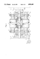
- FIG. 1 is a partly schematic broken front elevation showing the manner in which the form and rider rollers are mounted for oscillation with respect to the press water drum;
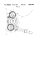
- FIG. 2 is a partly schematic side elevation showing the form roller and rider roller mounting structure.
- the numeral 10 designates the side frame members of a press, these frame members providing the principal support for most of the rolls and shafts of the press that are journaled therein.
- a plate cylinder 11 mounted for rotation between the side frame members.
- the water drum 12 is a roll which has an exterior layer of chrome of ceramic material which is hydrophilic so that the water that is present will become more uniformally dispersed for subsequent transfer.
- the water drum 12 is mounted for rotation on a shaft 15 that has its ends contained within journals 16 attached to side frame 10.
- the shaft 15 is stationary but the water drum 12 is mounted rotatably on shaft 15 and by means of the frictionless bearings 17.
- Retaining rings 18 are secured to the shaft 15 in the appropriate position to hold the water drum 12 in its preselected position between frame members 10.
- the present invention also contemplates a form roller 20 which is arranged for contact with the plate cylinder 11 when it is located in its operative position.
- the form roller 20 is supported by mounting means 21 which in the form shown is a plate like element 22 that has upwardly and downwardly extending lobes 23 and 24, respectively. Between the upwardly extending lobes the form roller 20 is held in position by means of threaded fasteners 25 acting against the shaft ends of the roll. The fasteners 25 can be adjusted to vary the distance between the form roller and the water roller 12 so that the amount of operating pressure between these rolls can be varied.
- Mounting means 21 are disposed on the shaft 15.
- the mounting means 21 are mounted on shaft 15 by means which permit axial movement of the mounting means parallel to the axis of the shaft of the water drum.
- the mounting means may comprise a linear bearing such as indicated by the numeral 30 or any other form of sleeve bearing that will permit axial movement.
- the mounting means 21 is shown being locked in position on the bearing means 30 by means of
- the downwardly extending portion 24 of mounting means 21 has a rider roller 31 mounted on it in the same fashion as the form roller 20 is mounted, specifically by means of fasteners 35 that attach directly to the mounting means 21.
- the rider roller 31 is covered with some sort of water absorbing material such as rubber or fabric and is used to receive water from a source of water such as the nozzle 40 and pass it on to the water drum 12 and from there on to the form roller 20 for deposition on the surface of plate cylinder 11. It should be noted at this point that the rider roller may or may not be present in all installations. Where the water or dampening solution is to be applied to the plate before the ink is applied, the rider roller 31 can be removed and the spray from nozzle 40 can be applied directly to the water drum 12. It is only when the ink is applied to the plate prior to the application of dampening fluid that the rider roller 31 is required.
- the mounting means 21 contains both the mounts for the form roller 20 and for the rider roller 31 so that by oscillating the mounting means to and fro between the opposite side frame members 10 the form and rider rollers will both also reciprocate. Reciprocating is effected by means of the drive means shown in FIG. 1. Specifically, a drive motor, not shown, has an eccentric 46 connected through linkage 47 to one of the mounting means 21. The rider roller 31 and the form roller 20 are oscillated at a slow rate for example at one cycle about every 30 seconds at a press operational speed of 50,000 impressions per hour. A DC motor is adequate to effect this mode of reciprocation.
- means are provided for rocking the mounting means 21 about the axis of the water drum 12.
- This means comprises a throw off cylinder 50 which is connected on one end to the mounting means 21 and at the other end to the side frame of the press. By tilting the mounting means 21 through action of the throw-off cylinder 50 the form roller can be moved out of contact with the plate cylinder or into contact with the plate cylinder, whichever position is desired.
Abstract
Description
Claims (5)
Priority Applications (7)
| Application Number | Priority Date | Filing Date | Title |
|---|---|---|---|
| US07/262,853 US4901640A (en) | 1988-10-19 | 1988-10-19 | Oscillating form roller dampener |
| CA000605674A CA1331848C (en) | 1988-10-19 | 1989-07-13 | Oscillating form roller dampener |
| DE198989113066T DE364675T1 (en) | 1988-10-19 | 1989-07-17 | DAMPING DEVICE WITH SWINGING APPLICATION ROLLER. |
| EP89113066A EP0364675B1 (en) | 1988-10-19 | 1989-07-17 | Oscillating form roller dampener |
| DE89113066T DE68911263T2 (en) | 1988-10-19 | 1989-07-17 | Moisture device with vibrating application roller. |
| JP1228484A JPH0315550A (en) | 1988-10-19 | 1989-09-05 | Offset printer |
| JP005207U JPH0744930U (en) | 1988-10-19 | 1995-05-30 | Offset printing machine |
Applications Claiming Priority (1)
| Application Number | Priority Date | Filing Date | Title |
|---|---|---|---|
| US07/262,853 US4901640A (en) | 1988-10-19 | 1988-10-19 | Oscillating form roller dampener |
Publications (1)
| Publication Number | Publication Date |
|---|---|
| US4901640A true US4901640A (en) | 1990-02-20 |
Family
ID=22999343
Family Applications (1)
| Application Number | Title | Priority Date | Filing Date |
|---|---|---|---|
| US07/262,853 Expired - Lifetime US4901640A (en) | 1988-10-19 | 1988-10-19 | Oscillating form roller dampener |
Country Status (5)
| Country | Link |
|---|---|
| US (1) | US4901640A (en) |
| EP (1) | EP0364675B1 (en) |
| JP (2) | JPH0315550A (en) |
| CA (1) | CA1331848C (en) |
| DE (2) | DE68911263T2 (en) |
Cited By (4)
| Publication number | Priority date | Publication date | Assignee | Title |
|---|---|---|---|---|
| US5540145A (en) * | 1993-02-22 | 1996-07-30 | Keller; James J. | Ink receptive dampening system for lithographic printing press |
| WO1998021045A1 (en) * | 1996-11-13 | 1998-05-22 | Keller James J | Ink receptive dampening system for lithographic printing press |
| US5979314A (en) * | 1994-08-19 | 1999-11-09 | Varn Products Company, Inc. | Lithographic dampener |
| USD740864S1 (en) * | 2012-12-14 | 2015-10-13 | Spiro International S.A. | Form roller assembly |
Citations (5)
| Publication number | Priority date | Publication date | Assignee | Title |
|---|---|---|---|---|
| US1012485A (en) * | 1911-06-22 | 1911-12-19 | Fred Waite | Rotary lithographic offset printing-machine. |
| US3994222A (en) * | 1976-04-30 | 1976-11-30 | Rockwell International Corporation | Ink roller vibrator mechanism |
| US4385559A (en) * | 1978-12-28 | 1983-05-31 | Roberto Jarach | Dampening device for offset printing machines for alternate and selective utilization of water or of a water-alcohol mixture |
| US4708058A (en) * | 1985-10-10 | 1987-11-24 | Smith Rpm Corporation | Water pulse spray dampening system and method for printing presses |
| US4809606A (en) * | 1987-06-19 | 1989-03-07 | Airsystems Inc. | Oscillating form roller and apparatus and method for controlling the oscillation thereof |
Family Cites Families (5)
| Publication number | Priority date | Publication date | Assignee | Title |
|---|---|---|---|---|
| US1730711A (en) * | 1926-04-06 | 1929-10-08 | Wood Newspaper Mach Corp | Inking mechanism for printing-press cylinders |
| DE8330123U1 (en) * | 1983-10-19 | 1984-01-12 | Heidelberger Druckmaschinen Ag, 6900 Heidelberg | INK FOR PRINTING MACHINES |
| US4493257A (en) * | 1983-10-25 | 1985-01-15 | Harris Graphics Corporation | Inker for a printing press |
| DE3424721C2 (en) * | 1984-07-05 | 1986-12-18 | M.A.N.- Roland Druckmaschinen AG, 6050 Offenbach | Inking unit for a printing press |
| JPH01229626A (en) * | 1988-03-10 | 1989-09-13 | Ikegai Gosu Kk | Dampening arrangement in offset press |
-
1988
- 1988-10-19 US US07/262,853 patent/US4901640A/en not_active Expired - Lifetime
-
1989
- 1989-07-13 CA CA000605674A patent/CA1331848C/en not_active Expired - Fee Related
- 1989-07-17 EP EP89113066A patent/EP0364675B1/en not_active Expired - Lifetime
- 1989-07-17 DE DE89113066T patent/DE68911263T2/en not_active Expired - Fee Related
- 1989-07-17 DE DE198989113066T patent/DE364675T1/en active Pending
- 1989-09-05 JP JP1228484A patent/JPH0315550A/en active Pending
-
1995
- 1995-05-30 JP JP005207U patent/JPH0744930U/en active Pending
Patent Citations (5)
| Publication number | Priority date | Publication date | Assignee | Title |
|---|---|---|---|---|
| US1012485A (en) * | 1911-06-22 | 1911-12-19 | Fred Waite | Rotary lithographic offset printing-machine. |
| US3994222A (en) * | 1976-04-30 | 1976-11-30 | Rockwell International Corporation | Ink roller vibrator mechanism |
| US4385559A (en) * | 1978-12-28 | 1983-05-31 | Roberto Jarach | Dampening device for offset printing machines for alternate and selective utilization of water or of a water-alcohol mixture |
| US4708058A (en) * | 1985-10-10 | 1987-11-24 | Smith Rpm Corporation | Water pulse spray dampening system and method for printing presses |
| US4809606A (en) * | 1987-06-19 | 1989-03-07 | Airsystems Inc. | Oscillating form roller and apparatus and method for controlling the oscillation thereof |
Cited By (5)
| Publication number | Priority date | Publication date | Assignee | Title |
|---|---|---|---|---|
| US5540145A (en) * | 1993-02-22 | 1996-07-30 | Keller; James J. | Ink receptive dampening system for lithographic printing press |
| US5865116A (en) * | 1993-02-22 | 1999-02-02 | Keller; James J. | Ink receptive dampening system for lithographic printing press |
| US5979314A (en) * | 1994-08-19 | 1999-11-09 | Varn Products Company, Inc. | Lithographic dampener |
| WO1998021045A1 (en) * | 1996-11-13 | 1998-05-22 | Keller James J | Ink receptive dampening system for lithographic printing press |
| USD740864S1 (en) * | 2012-12-14 | 2015-10-13 | Spiro International S.A. | Form roller assembly |
Also Published As
| Publication number | Publication date |
|---|---|
| CA1331848C (en) | 1994-09-06 |
| EP0364675B1 (en) | 1993-12-08 |
| DE68911263D1 (en) | 1994-01-20 |
| EP0364675A3 (en) | 1991-01-16 |
| DE364675T1 (en) | 1990-09-06 |
| EP0364675A2 (en) | 1990-04-25 |
| JPH0315550A (en) | 1991-01-23 |
| JPH0744930U (en) | 1995-12-05 |
| DE68911263T2 (en) | 1994-03-31 |
Similar Documents
| Publication | Publication Date | Title |
|---|---|---|
| JPH0236387B2 (en) | ||
| ATE25355T1 (en) | INKING UNIT FOR PRINTING PRESSES. | |
| JP2597906Y2 (en) | Wetting and inking equipment for offset printing presses | |
| US5778775A (en) | Printing unit with short inking system in a rotary printing machine for direct printing using a "waterless" planographic printing plate | |
| US4960052A (en) | Film inking apparatus for a printing press | |
| US2868118A (en) | Lithographic offset press plate dampening device | |
| US4901640A (en) | Oscillating form roller dampener | |
| US5341733A (en) | Short inking apparatus for a rotary press | |
| US5351614A (en) | Self-oscillating roller assembly and method | |
| US4404908A (en) | Arrangement for supplying ink to the printing plate of a printing press | |
| US2604848A (en) | Dampening apparatus and method for lithographic printing | |
| US3404626A (en) | Rotary priniting press | |
| US6827015B2 (en) | Form roller for printing press | |
| WO1998021045A1 (en) | Ink receptive dampening system for lithographic printing press | |
| US4621575A (en) | Printing unit of an offset rotary printing machine | |
| CA1066130A (en) | Ink ductor system | |
| US4981077A (en) | Dampening apparatus for lithographic press | |
| US3257940A (en) | Dampening system for lithographic offset printing presses | |
| JPH04234655A (en) | Improved non-key printing machine for non-key lithograph printing | |
| JPH03169555A (en) | Method to prepare for printing for printing device and usable printing device therefor | |
| US5265527A (en) | Offset printing press with emulsification control | |
| GB1559998A (en) | Letterpress and direct lithographic printing apparatus utilizing letterpress printing press | |
| US20100083856A1 (en) | Belted inker for a printing press | |
| US2866410A (en) | Inking mechanism | |
| US5423256A (en) | Form roller for printing press |
Legal Events
| Date | Code | Title | Description |
|---|---|---|---|
| AS | Assignment |
Owner name: ROCKWELL INTERNATIONAL CORPORATION, PITTSBURGH, PA Free format text: ASSIGNMENT OF ASSIGNORS INTEREST.;ASSIGNORS:NIEMIRO, THADDEUS A.;ZIMICH, DANIEL R.;REEL/FRAME:004965/0310 Effective date: 19880819 Owner name: ROCKWELL INTERNATIONAL CORPORATION, PENNSYLVANIA Free format text: ASSIGNMENT OF ASSIGNORS INTEREST;ASSIGNORS:NIEMIRO, THADDEUS A.;ZIMICH, DANIEL R.;REEL/FRAME:004965/0310 Effective date: 19880819 |
|
| STCF | Information on status: patent grant |
Free format text: PATENTED CASE |
|
| FEPP | Fee payment procedure |
Free format text: PAYOR NUMBER ASSIGNED (ORIGINAL EVENT CODE: ASPN); ENTITY STATUS OF PATENT OWNER: LARGE ENTITY |
|
| FPAY | Fee payment |
Year of fee payment: 4 |
|
| AS | Assignment |
Owner name: BANKERS TRUST COMPANY, A NEW YORK STATE BANKING CO Free format text: PATENT SECURITY AGREEMENT;ASSIGNOR:GOSS GRAPHIC SYSTEMS, INC., A DELAWARE CORPORATION;REEL/FRAME:008461/0095 Effective date: 19961015 |
|
| AS | Assignment |
Owner name: GOSS GRAPHIC SYSTEMS, INC., ILLINOIS Free format text: ASSIGNMENT OF ASSIGNORS INTEREST;ASSIGNOR:ROCKWELL INTERNATIONAL CORPORATION;REEL/FRAME:008104/0848 Effective date: 19961015 |
|
| FPAY | Fee payment |
Year of fee payment: 8 |
|
| AS | Assignment |
Owner name: BANKERS TRUST COMPANY, AS AGENT, CALIFORNIA Free format text: SECURITY AGREEMENT;ASSIGNOR:GOSS GRAPHIC SYSTEMS, INC.;REEL/FRAME:010514/0443 Effective date: 19991119 |
|
| FPAY | Fee payment |
Year of fee payment: 12 |
|
| AS | Assignment |
Owner name: U.S. BANK, N.A., AS COLLATERAL AGENT, MINNESOTA Free format text: SECURITY AGREEMENT;ASSIGNOR:GOSS INTERNATIONAL CORPORATION;REEL/FRAME:013913/0573 Effective date: 20030228 |
|
| AS | Assignment |
Owner name: GOSS INTERNATIONAL CORPORATION, ILLINOIS Free format text: ASSIGNMENT OF ASSIGNORS INTEREST;ASSIGNOR:GOSS GRAPHIC SYSTEMS, INC.;REEL/FRAME:013897/0864 Effective date: 20030325 |
|
| AS | Assignment |
Owner name: U.S. BANK, N.A., MINNESOTA Free format text: SECURITY AGREEMENT;ASSIGNOR:GOSS INTERNATIONAL CORPORATION;REEL/FRAME:015748/0855 Effective date: 20040806 Owner name: U.S. BANK, N.A.,MINNESOTA Free format text: SECURITY AGREEMENT;ASSIGNOR:GOSS INTERNATIONAL CORPORATION;REEL/FRAME:015748/0855 Effective date: 20040806 |
|
| AS | Assignment |
Owner name: U.S. BANK NATIONAL ASSOCIATION, AS COLLATERAL AGEN Free format text: SECURITY AGREEMENT;ASSIGNOR:GOSS INTERNATIONAL CORPORATION;REEL/FRAME:022960/0132 Effective date: 20090710 |
|
| AS | Assignment |
Owner name: GOSS INTERNATIONAL CORPORATION,ILLINOIS Free format text: RELEASE OF SECURITY INTEREST (GRANTED IN REEL 015748; FRAME: 0855);ASSIGNOR:U.S. BANK, N.A., AS COLLATERAL AGENT;REEL/FRAME:024563/0176 Effective date: 20100611 Owner name: GOSS INTERNATIONAL CORPORATION,ILLINOIS Free format text: RELEASE OF SECURITY INTEREST (GRANTED IN REEL 013913; FRAME: 0573);ASSIGNOR:U.S. BANK, N.A., AS COLLATERAL AGENT;REEL/FRAME:024563/0188 Effective date: 20100611 |
|
| AS | Assignment |
Owner name: GOSS INTERNATIONAL CORPORATION, ILLINOIS Free format text: RELEASE OF SECURITY INTEREST (GRANTED IN REEL 022960; FRAME 0132);ASSIGNOR:U.S. BANK, N.A., AS COLLATERAL AGENT;REEL/FRAME:025008/0324 Effective date: 20100914 |