US4901540A - Retifier colums for vapour generators - Google Patents
Retifier colums for vapour generators Download PDFInfo
- Publication number
- US4901540A US4901540A US07/207,808 US20780888A US4901540A US 4901540 A US4901540 A US 4901540A US 20780888 A US20780888 A US 20780888A US 4901540 A US4901540 A US 4901540A
- Authority
- US
- United States
- Prior art keywords
- column
- vapor
- reflux
- temperature
- valve
- Prior art date
- Legal status (The legal status is an assumption and is not a legal conclusion. Google has not performed a legal analysis and makes no representation as to the accuracy of the status listed.)
- Expired - Fee Related
Links
Images
Classifications
-
- B—PERFORMING OPERATIONS; TRANSPORTING
- B01—PHYSICAL OR CHEMICAL PROCESSES OR APPARATUS IN GENERAL
- B01D—SEPARATION
- B01D3/00—Distillation or related exchange processes in which liquids are contacted with gaseous media, e.g. stripping
- B01D3/14—Fractional distillation or use of a fractionation or rectification column
-
- B—PERFORMING OPERATIONS; TRANSPORTING
- B01—PHYSICAL OR CHEMICAL PROCESSES OR APPARATUS IN GENERAL
- B01D—SEPARATION
- B01D3/00—Distillation or related exchange processes in which liquids are contacted with gaseous media, e.g. stripping
- B01D3/007—Energy recuperation; Heat pumps
-
- B—PERFORMING OPERATIONS; TRANSPORTING
- B01—PHYSICAL OR CHEMICAL PROCESSES OR APPARATUS IN GENERAL
- B01D—SEPARATION
- B01D5/00—Condensation of vapours; Recovering volatile solvents by condensation
- B01D5/0057—Condensation of vapours; Recovering volatile solvents by condensation in combination with other processes
- B01D5/006—Condensation of vapours; Recovering volatile solvents by condensation in combination with other processes with evaporation or distillation
- B01D5/0063—Reflux condensation
Definitions
- This invention relates to a rectifier column in which one component is separated from a mixture of components and purified.
- a rectifier column having means for controlling a condensate supplied thereto to provide optimum operating conditions.
- vapor generated by a so-called reboiler, ascends the column through trays which collect intermediate concentrations of mixture by achieving an equilibrium in each tray between vapor ascending through the column and a liquid condensate descending through the tray system.
- Heat and mass are transferred in each tray by inducing turbulent contact of liquid and vapor phases so that ascending vapors are enriched with volatile components from the descending liquid while less volatile gases condense to dilute the descending liquid, thereby ensuring that ascending vapor is progressively concentrated while descending liquid is progressively diluted.
- a portion of the purified vapor provided by the column is condensed within the column by means of an internal heat exchanger to form the liquid condensate that is fed to the top tray and which passes down through the tray system to establish the aforesaid equilibrium conditions, so purifying the ascending vapor.
- This condensed vapor is termed reflux and directly affects product quality. If the quantity of reflux is too low, vapor concentration cannot occur to the required extent and the purity of the rectified vapor is unacceptably low, but if the quantity of reflux flow is too high, then the quantity of product, though of high quality, falls. Moreover heat is wastefully transferred from the reboiler to the rectifier column condenser.
- the invention provides a rectifier column for receiving a vapor output of a vapor generator, means for deriving reflux from the rectifier column output vapor externally of the column and means for modulating the flow of the reflux from said external means to the rectifier column.
- the reflux is obtained from a main system condenser which condenses the vapor output of the rectifier column and returns a portion as the reflux.
- Other arrangements are envisaged, though not described, in which an independent external condenser is employed for the purposes of generating the reflux.
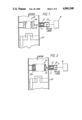
- FIG. 1 shows in diagrammatic form part of the rectifier column of a boiler showing the reflux liquid input incorporating a flow modulating valve
- FIG. 2 illustrates an alternative valve arrangement in the reflux column of FIG. 1;
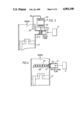
- FIG. 3 shows a further arrangement of the reflux column having a modified form of reflux modulating valve
- FIG. 4 shows yet another form of modulating valve for the rectifier column
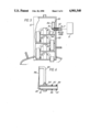
- FIG. 5 shows a typical rectifier column in section and including yet a further form of modulating valve for modulating the flow of reflux liquid
- FIG. 6 shows the construction of the modulating valve of FIG. 5 in greater detail
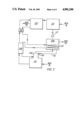
- FIG. 7 shows a novel heat pump system embodying the rectifier column fitted with a modulating valve according to the invention.
- FIG. 3 a somewhat different physical arrangement is shown.
- the spool valve though illustrated adjacent to the rectifier column, may in fact be remote therefrom.
- the bellows 16 is contained in a housing 22 which may be sited at a position which is intermediate the rectifier column 10 and the reflux condenser 9 and it may also be at ambient temperature.
- the bellows is linked to a sensor bulb 23, which is shown contained within the rectifier column, by means of suitably connecting tubing 24 and the whole actuator system is filled with an expansible wax.
- the temperature of the bulb changes the wax within it expands or contracts, thereby causing wax to be forced into the bellows or removed therefrom via the aforesaid tubing and causing actuation of the spool valve.
- This arrangement facilitates a simplification in the construction of the rectifier column, but the latter is not the only possible location for the bulb, as there are other locations within systems in which rectifier columns are used, where the temperature of fluids are related to the quantity of reflux required at any instant for optimum performance; downstream of an expansion valve in a heat pump is one such position.
- FIG. 4 A further alternative, this time again situated in the rectifier column, is shown in FIG. 4. It comprises a post 25 extending into the interior of the rectifier column, attached at one end to a plug 26 in the reflux inlet and having a free end.
- An apertured disc closure member 27 co-operates with an orifice in the plug 26 and is rotatably mounted upon the post.
- a helical element 28 formed from a bimetal strip has a first end attached to the disc at a radial position thereon and a second end attached to the free end of the post.
- the aperture in the plug is obstructed to a greater or a lesser degree by the disc, thus modulating the flow of reflux from the condenser 9.
- FIGS. 5 and 6 there is shown a typical rectifier column 10 fitted with yet a further form of reflux modulating valve.
- This is essentially an orifice 30 defined by a tube 31 which may be a simple sealing push fit into the reflux inlet duct 32 which enters the rectifier column through its vertical wall 33 and forms an end part of the conduit 7,
- a threaded collar 34 (best seen in FIG. 6) is carried on a corresponding threaded portion of the tube and to the collar is attached a dogleg support arm 35 which tends to overhang the orifice.
- a bimetal strip 36 is attached to the dogleg of this support arm at one end which at its other end co-operates with orifice 30 in the tube 31 to control the flow of reflux liquid therethrough.
- the bimetal strip is mounted with an orientation which causes it to engage the tube when the temperature around the reflux input falls and to move away therefrom when the temperature rises. In this way because the temperature falls with increasing ammonia content in the solution in the trays, the cooler vapor passing the bimetal strip tends to close the valve, and as the temperature rises due to reduced ammonia the valve tends to open to admit further quantities of reflux.
- the operation of the valve may be adjusted by rotating the collar on the tube, which by virtue of the threaded engagement, causes it to move in an axial direction therealong. Conveniently, once set, it is locked in position by means of a set screw (not shown). Also conveniently the collar may take the external form of a nut (not shown) for easy adjustment.
- Sealing engagment of the tube 30 in the reflux inlet duct 32 is provided by means of a pair of “O" rings 37, 38, which are respectively partially housed in circumferential slots 39, 40 provided on the external surface of the tube. These "O" rings engage the inner surface of the reflux inlet duct 32 when the valve is inserted therein.
- FIG. 7 An example of a novel advantageous heat pump system which has been realized by the use of a present reflux valve is disclosed in FIG. 7 which illustrates the aspects of the system concerned with the transportation of the system fluid mediums.
- a pump 100 pumps a strong solution from the absorber 102 to the rectifier column 104 via a heat receiving coil 105 in the condenser 106 and a weak/strong solution heat exchanger 108, on both occasions picking up heat from other fluids in the system.
- This pumped solution gives off a volatile fraction in the rectifier column and the remainder drains as a weak solution into the generator 110 where it receives further heat and as a consequence releases even more vapor.
- the heated but weakened solution is ducted to the pump as its working fluid, passing thereto via the heat exchanger 108 where some of its sensible heat is transferred to the aforesaid strong solution passing in the opposite direction. From the working chamber of the pump the weak solution flows into the input of the absorber 102 to complete the circulation of the solution.
- Vapor leaving the rectifier column 104 is ducted to the condenser 106 where its latent heat is removed.
- the condensate is split at the condenser, a fraction thereof being returned as reflux to the rectifier column 104 via a conduit 118 and the reflux valve 116, while the major proportion flows through an expansion valve 112 from there into an evaporator 114 where it is vaporized.
- the vapor is ducted to the absorber 102 where it enters into solution in the soluble medium of the system.
- the split in the condensate has to be controlled.
- This control is performed by the reflux valve 116 situated at the reflux inlet to the rectifier column.
- the control is exercised in one of the manners hereinbefore described.
Landscapes
- Chemical & Material Sciences (AREA)
- Chemical Kinetics & Catalysis (AREA)
- Air Humidification (AREA)
- Vaporization, Distillation, Condensation, Sublimation, And Cold Traps (AREA)
- Physical Or Chemical Processes And Apparatus (AREA)
- Devices For Medical Bathing And Washing (AREA)
- Temperature-Responsive Valves (AREA)
- Control Of Eletrric Generators (AREA)
- Engine Equipment That Uses Special Cycles (AREA)
- Synchronous Machinery (AREA)
Abstract
Description
Claims (16)
Applications Claiming Priority (2)
| Application Number | Priority Date | Filing Date | Title |
|---|---|---|---|
| GB878714337A GB8714337D0 (en) | 1987-06-18 | 1987-06-18 | Rectifier columns |
| GB8714337 | 1987-06-18 |
Publications (1)
| Publication Number | Publication Date |
|---|---|
| US4901540A true US4901540A (en) | 1990-02-20 |
Family
ID=10619177
Family Applications (1)
| Application Number | Title | Priority Date | Filing Date |
|---|---|---|---|
| US07/207,808 Expired - Fee Related US4901540A (en) | 1987-06-18 | 1988-06-17 | Retifier colums for vapour generators |
Country Status (7)
| Country | Link |
|---|---|
| US (1) | US4901540A (en) |
| EP (1) | EP0295951B1 (en) |
| AT (1) | ATE84237T1 (en) |
| CA (1) | CA1325997C (en) |
| DE (1) | DE3877266T2 (en) |
| ES (1) | ES2037832T3 (en) |
| GB (1) | GB8714337D0 (en) |
Cited By (1)
| Publication number | Priority date | Publication date | Assignee | Title |
|---|---|---|---|---|
| WO1991008426A1 (en) * | 1989-11-28 | 1991-06-13 | Erickson Donald C | Rectification reflux by latent heat exchange with partially depressurized absorbent |
Citations (7)
| Publication number | Priority date | Publication date | Assignee | Title |
|---|---|---|---|---|
| US2240177A (en) * | 1937-12-23 | 1941-04-29 | Hoover Co | Refrigeration |
| US2271542A (en) * | 1936-08-08 | 1942-02-03 | Hoover Co | Rectifier for refrigerating systems |
| US2556753A (en) * | 1948-09-03 | 1951-06-12 | Tide Water Associated Oil Comp | Electronic switching system |
| CH368948A (en) * | 1957-12-21 | 1963-04-30 | Basf Ag | Process for setting the reflux ratio in rectifications and device for carrying out the process |
| GB982452A (en) * | 1961-09-02 | 1965-02-03 | Mission Mfg Co | Filter unit for oil heating plants |
| US3658655A (en) * | 1969-09-19 | 1972-04-25 | Peter N Heere | Direct reading relux rating controller for a distillation apparatus |
| GB2164395A (en) * | 1984-09-04 | 1986-03-19 | Chausson Usines Sa | Pressure regulating and by- passing device for heat engine lubricating circuits |
-
1987
- 1987-06-18 GB GB878714337A patent/GB8714337D0/en active Pending
-
1988
- 1988-06-17 AT AT88305568T patent/ATE84237T1/en not_active IP Right Cessation
- 1988-06-17 DE DE8888305568T patent/DE3877266T2/en not_active Expired - Fee Related
- 1988-06-17 US US07/207,808 patent/US4901540A/en not_active Expired - Fee Related
- 1988-06-17 CA CA000569815A patent/CA1325997C/en not_active Expired - Fee Related
- 1988-06-17 EP EP88305568A patent/EP0295951B1/en not_active Expired - Lifetime
- 1988-06-17 ES ES198888305568T patent/ES2037832T3/en not_active Expired - Lifetime
Patent Citations (7)
| Publication number | Priority date | Publication date | Assignee | Title |
|---|---|---|---|---|
| US2271542A (en) * | 1936-08-08 | 1942-02-03 | Hoover Co | Rectifier for refrigerating systems |
| US2240177A (en) * | 1937-12-23 | 1941-04-29 | Hoover Co | Refrigeration |
| US2556753A (en) * | 1948-09-03 | 1951-06-12 | Tide Water Associated Oil Comp | Electronic switching system |
| CH368948A (en) * | 1957-12-21 | 1963-04-30 | Basf Ag | Process for setting the reflux ratio in rectifications and device for carrying out the process |
| GB982452A (en) * | 1961-09-02 | 1965-02-03 | Mission Mfg Co | Filter unit for oil heating plants |
| US3658655A (en) * | 1969-09-19 | 1972-04-25 | Peter N Heere | Direct reading relux rating controller for a distillation apparatus |
| GB2164395A (en) * | 1984-09-04 | 1986-03-19 | Chausson Usines Sa | Pressure regulating and by- passing device for heat engine lubricating circuits |
Cited By (2)
| Publication number | Priority date | Publication date | Assignee | Title |
|---|---|---|---|---|
| WO1991008426A1 (en) * | 1989-11-28 | 1991-06-13 | Erickson Donald C | Rectification reflux by latent heat exchange with partially depressurized absorbent |
| US5033274A (en) * | 1989-11-28 | 1991-07-23 | Erickson Donald C | Rectification reflux by latent heat exchange with partially depressurized absorbent |
Also Published As
| Publication number | Publication date |
|---|---|
| DE3877266T2 (en) | 1993-04-29 |
| EP0295951A3 (en) | 1989-05-31 |
| EP0295951A2 (en) | 1988-12-21 |
| DE3877266D1 (en) | 1993-02-18 |
| GB8714337D0 (en) | 1987-07-22 |
| ES2037832T3 (en) | 1993-07-01 |
| CA1325997C (en) | 1994-01-11 |
| ATE84237T1 (en) | 1993-01-15 |
| EP0295951B1 (en) | 1993-01-07 |
Similar Documents
| Publication | Publication Date | Title |
|---|---|---|
| US4258899A (en) | Actuating apparatus for adjusting a movable element, particularly the closure member of a valve | |
| CA1054812A (en) | Refrigeration system subcooling control | |
| US3621906A (en) | Control system for heat pipes | |
| US3651655A (en) | Control system for multiple stage absorption refrigeration system | |
| JP2637939B2 (en) | Coolant flow control device | |
| AU722139B2 (en) | Process for the control of a refrigeration system, as well as a refrigeration system and expansion valve | |
| US4309243A (en) | Vertical tube distillers | |
| US4901540A (en) | Retifier colums for vapour generators | |
| US3826719A (en) | Fractionator control system for reboiling narrow boiling range liquids | |
| US3451897A (en) | Apparatus for reconcentrating glycol and the like | |
| US4322951A (en) | Control device and method for conserving fuel in an absorption refrigeration system | |
| US4300626A (en) | Heat-pipe thermostats of high precision | |
| US4323220A (en) | Actuating apparatus for adjusting a movable element, particularly the closure member of a valve | |
| US2228767A (en) | Thermal control device | |
| US2269100A (en) | Refrigeration | |
| US2856160A (en) | Temperature control system | |
| US2150678A (en) | Condenser | |
| US1404844A (en) | Thermostatic regulating device | |
| US2269101A (en) | Heat transfer system | |
| CA1134157A (en) | Means and method for independently controlling vapor compression cycle device evaporator superheat and thermal transfer capacity | |
| US2333780A (en) | Continuous absorption refrigerating system | |
| CA1089402A (en) | Water distiller with cone shaped condenser | |
| US1981313A (en) | Thermostatically operated valve | |
| US2613505A (en) | Control valve, such as for refrigerating systems | |
| US1780417A (en) | Control device |
Legal Events
| Date | Code | Title | Description |
|---|---|---|---|
| AS | Assignment |
Owner name: FOSTER WHEELER ENERGY LIMITED, FOSTER WHEELER HOUS Free format text: ASSIGNMENT OF ASSIGNORS INTEREST.;ASSIGNORS:HOUGHTON, FRED;HOLMES, PAUL;REEL/FRAME:004930/0996 Effective date: 19880803 Owner name: FOSTER WHEELER ENERGY LIMITED,GREAT BRITAIN Free format text: ASSIGNMENT OF ASSIGNORS INTEREST;ASSIGNORS:HOUGHTON, FRED;HOLMES, PAUL;REEL/FRAME:004930/0996 Effective date: 19880803 |
|
| AS | Assignment |
Owner name: BRITISH GAS PLC Free format text: ASSIGNMENT OF ASSIGNORS INTEREST.;ASSIGNOR:FOSTER WHEELER ENERGY LIMITED;REEL/FRAME:005926/0302 Effective date: 19911028 |
|
| FEPP | Fee payment procedure |
Free format text: PAYOR NUMBER ASSIGNED (ORIGINAL EVENT CODE: ASPN); ENTITY STATUS OF PATENT OWNER: LARGE ENTITY |
|
| FPAY | Fee payment |
Year of fee payment: 4 |
|
| FPAY | Fee payment |
Year of fee payment: 8 |
|
| REMI | Maintenance fee reminder mailed | ||
| LAPS | Lapse for failure to pay maintenance fees | ||
| STCH | Information on status: patent discontinuation |
Free format text: PATENT EXPIRED DUE TO NONPAYMENT OF MAINTENANCE FEES UNDER 37 CFR 1.362 |
|
| FP | Lapsed due to failure to pay maintenance fee |
Effective date: 20020220 |