US4901532A - System for routing preseparator drains - Google Patents
System for routing preseparator drains Download PDFInfo
- Publication number
- US4901532A US4901532A US07/253,290 US25329088A US4901532A US 4901532 A US4901532 A US 4901532A US 25329088 A US25329088 A US 25329088A US 4901532 A US4901532 A US 4901532A
- Authority
- US
- United States
- Prior art keywords
- drain
- liquid
- collection tank
- preseparator
- eductor
- Prior art date
- Legal status (The legal status is an assumption and is not a legal conclusion. Google has not performed a legal analysis and makes no representation as to the accuracy of the status listed.)
- Expired - Fee Related
Links
Images
Classifications
-
- F—MECHANICAL ENGINEERING; LIGHTING; HEATING; WEAPONS; BLASTING
- F01—MACHINES OR ENGINES IN GENERAL; ENGINE PLANTS IN GENERAL; STEAM ENGINES
- F01K—STEAM ENGINE PLANTS; STEAM ACCUMULATORS; ENGINE PLANTS NOT OTHERWISE PROVIDED FOR; ENGINES USING SPECIAL WORKING FLUIDS OR CYCLES
- F01K7/00—Steam engine plants characterised by the use of specific types of engine; Plants or engines characterised by their use of special steam systems, cycles or processes; Control means specially adapted for such systems, cycles or processes; Use of withdrawn or exhaust steam for feed-water heating
- F01K7/16—Steam engine plants characterised by the use of specific types of engine; Plants or engines characterised by their use of special steam systems, cycles or processes; Control means specially adapted for such systems, cycles or processes; Use of withdrawn or exhaust steam for feed-water heating the engines being only of turbine type
- F01K7/22—Steam engine plants characterised by the use of specific types of engine; Plants or engines characterised by their use of special steam systems, cycles or processes; Control means specially adapted for such systems, cycles or processes; Use of withdrawn or exhaust steam for feed-water heating the engines being only of turbine type the turbines having inter-stage steam heating
- F01K7/223—Inter-stage moisture separation
Definitions
- This invention relates to steam turbines and, more particularly, to an apparatus for improving the effectiveness of transporting preseparator condensate from drain collection tanks to moisture separator reheaters drain tanks.
- 4,527,396 issued to Silvestri and assigned to Westinghouse Corporation, discloses a moisture preseparator for removing erosion-causing entrained liquid from a moisture-laden stream of gas flowing in the exhaust pipes of a steam turbine. That invention is part of a larger scheme to remove liquid entrained in the exhaust steam flowing in the entire steam turbine exhaust system and to diminish exhaust pipe erosion in steam turbines, as set forth in U.S. Pat. No. 4,622,819 by Silvestri and Draper, and assigned to Westinghouse Electric Corporation.
- a Swiss design for a moisture preseparator also discloses the problem of corrosion from the moisture content of steam leaving a high pressure turbine and is described in "Moisture Separator and Cycle Efficiency Improvements by Installing Moisture Preseparators", von Boekh, Hutton & Patrick, ASME Joint Power Generation Conference Paper No. 84-JPGC-Pwr-30, 1984.
- Moisture separated from the exhaust system is typically routed first to a collection tank and then to a moisture separator reheater drain tank.
- a major concern with respect to the incorporation of moisture preseparators into existing nuclear steam turbine systems is the avoidance of upsets in the drain system of the separator stage in the moisture separator reheaters. It has been found that the operating pressures of the moisture preseparators, customarily located close to the turbine exhaust, are higher than those of the drain lines from the moisture separator reheaters. The pressure differences are in the neighborhood of two to three percent of turbine exhaust pressure. There is also evidence of pressure recovery of steam velocity in the preseparator water collection zone, between the preseparator inner wall and either the exhaust snout or crossunder pipe wall. This phenomenon can increase the pressure differential to four percent of turbine exhaust pressure.
- MSR drain tank may be located above the preseparator collection tank.
- Preseparator drain water is ordinarily saturated with vapor. If it were to flow uphill, the two-to-four percent pressure differential would result in flashing.
- MSR drain tanks may have tank level control systems, such as a valve in the MSR drain line, which would be rendered ineffective by routing the preseparator drained liquid into the MSR exit drain line. In such a configuration, an alternative would be to rout the liquid from the preseparator drain tank to a heater with a level control and connection to the heater.
- the present invention provides a routing system for preseparator drain liquid, after it has exited the preseparator system, from its collection tank through an eductor and then to one or more MSR drain tanks.
- the eductor which operates on the Venturi principle, serves the function of acting as a pump to accelerate the liquid and to further cool the liquid.
- the preseparator collection tank liquid is used as the suction fluid.
- the motive fluid is pressurized condensate taken from the discharge of one or more turbine feedwater heaters. The combination is then discharged into the MSR drain tank or tanks.
- the pressurized heater condensate is ordinarily cooler than the collection tank water.
- the eductor mixes the condensate with the collection tank water thereby producing eductor discharge water cooler than the collection tank water by ten to twenty degrees Fahrenheit.
- the cooler eductor discharge can now incur a much greater drop in pressure, from thirteen to twenty percent of turbine exhaust pressure, before the danger of flashing arises.
- the collection tank for the preseparator drain water has a discharge line projecting inside the tank to maintain a minimum water level, which in turn provides for submerged entry of the preseparator drain water. This arrangement prevents the flow of steam down the preseparator drain pipes.
- the system also provides for spraying a small amount of heater condensate into the collection tank to slightly cool the drains in order to provide additional margin to protect against flashing in the line between the collection tank and the eductor.
- Benefits of the invention include an overall increase in plant thermal efficiency, compared to the output loss of a conventional drain system without an eductor in which insulation is removed to cool the drain water from the preseparator. Another benefit is the reduction in size of the preseparator piping system downstream of the collector drain tank.
- a conventional system without eductor requires twelve to sixteen inch diameter drain lines to prevent flashing, whereas with the eductor, the drain line diameter can be reduced to six inches, resulting in significant savings in the cost of purchasing and installing a preseparator system.
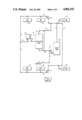
- FIG. 1 is a simplified schematic representation of a conventional preseparator drain routing system to a moisture separator reheater drain tank in one type of steam turbine;
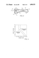
- FIG. 2 is a cross-sectional view of one form of eductor which may be used with the present invention showing the direction, inlet, mixing, compression and discharge of both motive and suction fluid;
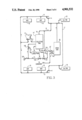
- FIG. 3 is a simplified representation of an improved preseparator drain routing system incorporating the teachings of the present invention
- FIG. 4 is a graph of performance data of two types of eductors comparing NPSH versus efficiency factor over a range of operation.
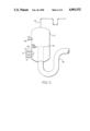
- FIG. 5 is a planar view of a collection tank and drain line configuration used with the present invention, upstream of the eductor.
- FIG. 1 A typical installation of a moisture preseparator drain system 10 in a nuclear steam turbine system is shown schematically in FIG. 1.
- Liquid separated from moisture-laden exhaust steam exits a turbine exhaust nozzle 12 and feeds into a collection tank 14.
- a high pressure steam turbine will have at least two steam exhaust nozzles or snouts 12, each of which will have a plurality of preseparation ports emptying liquid from exhaust nozzles 12 through one or more drain lines 13 into collection tank 14.
- Collection tank 14 is provided with a vent 16 through which vapor formed during transients is routed to second point feedwater heaters 18 via vent line 15 and extraction steam line 17.
- the illustrative system includes multiple moisture separator reheaters (MSR) 19 coupled to receive exhaust steam from nozzle 12 via various steam lines and cross-under piping 21.
- MSR moisture separator reheaters
- preseparation liquid is routed into the moisture separator reheater drain tank 20, the flow into the tank being controlled by a non-return valve 22.
- FIG. 2 A schematic representation of the eductor portion 102 of the present invention 100 is shown in FIG. 2.
- the eductor operates in the well-known Venturi effect, a corollary of Bernouilli's Law.
- Eductor 102 has a nozzle end 104 equipped with nozzle 110 through which the motive fluid, represented by arrow V1, is projected into the eductor 102 towards the diffuser 116.
- the motive fluid is high pressure condensate from the discharge of one or more heaters, not shown.
- Preseparator collection tank drain liquid, or suction fluid, represented by arrow Vs is entrained by motive fluid into eductor 102 through an inlet 114 in body 112 at the nozzle end 104.
- the motive fluid and suction fluid merge with a momentum interchange in the entrainment section 118 of the diffuser 116 wherein the body 112 tapers to a narrower throat section 120.
- the flow of the merged fluids through the entrainment section 118 is represented by arrow Vn.
- the merged fluids, indicated by arrow Vt have reached a common velocity, i.e., the motive fluid has slowed and the suction fluids has accelerated.
- the last section 124 of eductor 102 has a reverse taper to an outlet 126 larger than the throat 120. In this last section 124, the velocity of the combined fluids undergoes a corresponding decrease.
- the outlet 126 discharges the combined fluids, indicated by arrow V2, at lower temperature and at higher pressure than that of the suction fluid, Vs, into line 140'.
- a momentum interchange between the suction fluid and the motive fluid takes place in the eductor and effects a heat and pressure exchange between the motive fluid V1 and the suction fluid Vs which substantially reduces the risk of flashing downstream of the eductor 102.
- FIG. 3 is a schematic flow chart of the moisture preseparator drain system incorporating the teachings of the invention. It is identical in all respects to FIG. 1, except for the introduction of the eductor system. Eductor 102 is shown in line between collection tank 14' and non-return valve 22'.
- the motive fluid, V1 comes from a high pressure water supply, illustrated as a pump 100 although other sources of fluid at sufficient pressure and temperature are available within a turbine system as is discussed below.
- V1 The flow of motive fluid V1 is controlled upstream of eductor 102 by two valves, a shutoff valve 130 followed by a control valve 132.
- the valves 130 and 132 are controlled in response to water level in collection tank 14' (see level control or sensor 150 in FIG. 5).
- a controller 134 operates valves 130 and 132 to maintain a desired water level in tank 14'.
- the water level is selected to prevent flooding the tank so that water does not back-up into the exhaust system and to prevent the level from becoming so low that steam is pulled into the separator system.
- V1 is tapped either from a main condensate discharge of a heater cascading other heater drains, or from the discharge of a heater pumping ahead the drain from another heater (in lieu of pump 100).
- the heater discharge will have elevational pressure head in excess of that of the preseparator collection tank fluid.
- the heater discharge requires conventional pumping in any event to its next destination, a second-point heater. Tapping some of this discharge to use as motive fluid for the eductor results in a very small relative power loss which is more than offset by reduced demands on other elements of the entire power plant, as will become evident further on in this disclosure.
- FIG. 4 plots the performance characteristics of two types of eductor at various levels of net positive suction head (NPSH) and efficiency factor.
- the performance data of eductors was taken from Karassik, Krutzch, Fraser and Messina, Pump Handbook (McGraw-Hill, 1976). According to data published therein, three-and-a-half to six pounds of suction fluid can be pumped by one pound of motive fluid, depending on their respective pressures at the eductor. It is calculated from these data that the mixing of the motive fluid, pressurized condensate V1 from one or more turbine heaters with the preseparator drain collection tank liquid, Vs, would result in eductor water V2 cooler by ten to twenty degrees Fahrenheit than the collection tank liquid. V2 discharge at outlet 126 could incur a pressure drop of thirteen to twenty-one percent before it would flash.
- FIG. 5 shows collection tank 14' equipped with a discharge pipe 140 projecting upward within tank 14' to maintain water level 142 at sufficient height to allow submerged entry of drain lines 13 through apertures 14'. This feature of the invention will prevent unwanted steam flow down drain lines 13.
- a small vent line 144 is shown at the top of tank 14' which is routed to a downstream crossunder pipe, not shown.
- a sensor 150 senses the water level 142 and activates control valve 132 through controller 134 for controlling the flow of motive fluid V1 into eductor 102.
- Another feature of the invention comprises spraying a small amount of cool heater discharge condensate into collection tank 14' to slightly precool the drain lines 13, thereby providing an extra margin of flash prevention in discharge pipe 140 between collection tank 14' and eductor 102.
- Such spray may be obtained from the source of the motive fluid, e.g., pump 100, coupled by a control valve 146 to tank 14'.
- a spray head 148 may be positioned in tank 14' and coupled to valve 146 by water line 149.
- the calculated pressure differentials produced by the invention as noted herein are based upon a lowering of the saturation pressure of the contents of the preseparator drain collection tank 14' by 5 p.s.i. through the use of this spray.
- the present invention into an existing nuclear powered steam turbine generator system will result in a small loss in power output of the generator system.
- the loss varies with heater drain configuration, supply pressure of the motive fluid, discharge pressure from the eductor collection tank water pressure and MSR drain tank elevation.
- the output loss has been calculated to be between 117 kilowatts and 200 kilowatts out of a total output of 1,154,745 kilowatts, for condensate from a heater in a cycle which cascades all heater drains.
- the loss would be between twenty-nine and thirty-four kilowatts. These losses are negligible in relation to the alternative loss of 106 kilowatts of output in the case of a conventional drain system, without eductor, which relies on omitting insulation from the drain line to cool the preseparator drain liquid.
- the calculated power loss for the conventional system is related to increased load upon plant ventilation and cooling caused by dissipation of heat from the uninsulated drain lines, and does not take into account efficiency losses and costs of other problems associated with flashing in the moisture separator reheater system, which are not effectively prevented by the conventional drainage system.
- Another benefit of the invention is that it has little, if any, effect on existing plant ventilation and cooling systems.
- a preseparator installation using a conventional drain system without eductor makes additional demands on the ventilation systems in the area adjacent to the preseparators.
- the ventilation systems in some existing plants do not have the capacity for added heat load.
- Still another major benefit of the present invention is the reduction in the size of the preseparator drain pipe 142 downstream of the collection tank 14'. Without eductor 102, twelve to sixteen inch diameter pipe is required to protect against flashing. With eductor, the diameter of pipe 142 may be reduced to six inches. This results in a substantial saving in equipment and installation costs of an entire preseparator system.
- the subject invention is useful over a wide range of preseparator moisture removal effectiveness.
- the twelve and sixteen inch drain lines now in use as drain lines are typical for a preseparator effectiveness approaching thirty-five percent of total turbine exhaust moisture removal.
- the eductor system is more easily adapted to accommodate such improvements in conventional drain systems.
Landscapes
- Engineering & Computer Science (AREA)
- Chemical & Material Sciences (AREA)
- Combustion & Propulsion (AREA)
- Mechanical Engineering (AREA)
- General Engineering & Computer Science (AREA)
- Jet Pumps And Other Pumps (AREA)
- Control Of Turbines (AREA)
- Turbine Rotor Nozzle Sealing (AREA)
- Vaporization, Distillation, Condensation, Sublimation, And Cold Traps (AREA)
- Control Of Non-Electrical Variables (AREA)
Priority Applications (6)
| Application Number | Priority Date | Filing Date | Title |
|---|---|---|---|
| US07/253,290 US4901532A (en) | 1988-10-05 | 1988-10-05 | System for routing preseparator drains |
| IT8941704A IT1233547B (it) | 1988-10-05 | 1989-09-22 | Sistema di turbina a vapore impiegante un sistema di drenaggio pre-separatore di umidita' per impedire l'erosione di condutture di scarico. |
| ES8903336A ES2015495A6 (es) | 1988-10-05 | 1989-10-04 | Una instalacion de turbina de vapor. |
| KR1019890014327A KR0157042B1 (ko) | 1988-10-05 | 1989-10-05 | 사전 분리기 배수관의 경로에 대한 향상된 시스템 |
| CN89107650A CN1020495C (zh) | 1988-10-05 | 1989-10-05 | 改进的预分离器疏水输送系统 |
| JP1261225A JP2696124B2 (ja) | 1988-10-05 | 1989-10-05 | 蒸気タービン装置 |
Applications Claiming Priority (1)
| Application Number | Priority Date | Filing Date | Title |
|---|---|---|---|
| US07/253,290 US4901532A (en) | 1988-10-05 | 1988-10-05 | System for routing preseparator drains |
Publications (1)
| Publication Number | Publication Date |
|---|---|
| US4901532A true US4901532A (en) | 1990-02-20 |
Family
ID=22959651
Family Applications (1)
| Application Number | Title | Priority Date | Filing Date |
|---|---|---|---|
| US07/253,290 Expired - Fee Related US4901532A (en) | 1988-10-05 | 1988-10-05 | System for routing preseparator drains |
Country Status (6)
| Country | Link |
|---|---|
| US (1) | US4901532A (es) |
| JP (1) | JP2696124B2 (es) |
| KR (1) | KR0157042B1 (es) |
| CN (1) | CN1020495C (es) |
| ES (1) | ES2015495A6 (es) |
| IT (1) | IT1233547B (es) |
Cited By (2)
| Publication number | Priority date | Publication date | Assignee | Title |
|---|---|---|---|---|
| US6155054A (en) * | 1998-08-18 | 2000-12-05 | Asea Brown Boveri Ag | Steam power plant and method of and cleaning its steam/water cycle |
| US20100005806A1 (en) * | 2008-07-14 | 2010-01-14 | Donnelly Brian G | Eductor system for a gas turbine engine |
Families Citing this family (4)
| Publication number | Priority date | Publication date | Assignee | Title |
|---|---|---|---|---|
| US7735325B2 (en) * | 2002-04-16 | 2010-06-15 | Research Sciences, Llc | Power generation methods and systems |
| RU2425280C2 (ru) * | 2006-09-19 | 2011-07-27 | Альстом Текнолоджи Лтд | Водоотделитель для паротурбинных установок |
| CN104775861B (zh) * | 2015-05-08 | 2016-06-29 | 中国电力工程顾问集团华东电力设计院有限公司 | 火电厂抽水蓄能热力系统 |
| CN106168380B (zh) * | 2016-06-14 | 2018-03-27 | 蒙自矿冶有限责任公司 | 节能环保型烟气脱硫烟囱高效疏水排淤装置 |
Citations (4)
| Publication number | Priority date | Publication date | Assignee | Title |
|---|---|---|---|---|
| US3320729A (en) * | 1963-05-17 | 1967-05-23 | Westinghouse Electric Corp | Apparatus for removing liquid from a liquid laden gas stream |
| US4527396A (en) * | 1983-09-23 | 1985-07-09 | Westinghouse Electric Corp. | Moisture separating device |
| US4622819A (en) * | 1985-01-29 | 1986-11-18 | Westinghouse Electric Corp. | Steam turbine exhaust pipe erosion prevention system |
| US4803841A (en) * | 1987-09-30 | 1989-02-14 | Westinghouse Electric Corp. | Moisture separator for steam turbine exhaust |
-
1988
- 1988-10-05 US US07/253,290 patent/US4901532A/en not_active Expired - Fee Related
-
1989
- 1989-09-22 IT IT8941704A patent/IT1233547B/it active
- 1989-10-04 ES ES8903336A patent/ES2015495A6/es not_active Expired - Lifetime
- 1989-10-05 CN CN89107650A patent/CN1020495C/zh not_active Expired - Fee Related
- 1989-10-05 JP JP1261225A patent/JP2696124B2/ja not_active Expired - Fee Related
- 1989-10-05 KR KR1019890014327A patent/KR0157042B1/ko not_active IP Right Cessation
Patent Citations (4)
| Publication number | Priority date | Publication date | Assignee | Title |
|---|---|---|---|---|
| US3320729A (en) * | 1963-05-17 | 1967-05-23 | Westinghouse Electric Corp | Apparatus for removing liquid from a liquid laden gas stream |
| US4527396A (en) * | 1983-09-23 | 1985-07-09 | Westinghouse Electric Corp. | Moisture separating device |
| US4622819A (en) * | 1985-01-29 | 1986-11-18 | Westinghouse Electric Corp. | Steam turbine exhaust pipe erosion prevention system |
| US4803841A (en) * | 1987-09-30 | 1989-02-14 | Westinghouse Electric Corp. | Moisture separator for steam turbine exhaust |
Non-Patent Citations (2)
| Title |
|---|
| Dr. Peter von Boeckh et al.; "Moisture Separator and Cycle Efficiency Improvements by Installing Moisture Preseparators"; ASME Journal; pp. 1-6, (no date). |
| Dr. Peter von Boeckh et al.; Moisture Separator and Cycle Efficiency Improvements by Installing Moisture Preseparators ; ASME Journal; pp. 1 6, (no date). * |
Cited By (2)
| Publication number | Priority date | Publication date | Assignee | Title |
|---|---|---|---|---|
| US6155054A (en) * | 1998-08-18 | 2000-12-05 | Asea Brown Boveri Ag | Steam power plant and method of and cleaning its steam/water cycle |
| US20100005806A1 (en) * | 2008-07-14 | 2010-01-14 | Donnelly Brian G | Eductor system for a gas turbine engine |
Also Published As
| Publication number | Publication date |
|---|---|
| JP2696124B2 (ja) | 1998-01-14 |
| IT8941704A0 (it) | 1989-09-22 |
| CN1041637A (zh) | 1990-04-25 |
| CN1020495C (zh) | 1993-05-05 |
| KR0157042B1 (ko) | 1998-11-16 |
| ES2015495A6 (es) | 1990-08-16 |
| IT1233547B (it) | 1992-04-03 |
| KR900006641A (ko) | 1990-05-08 |
| JPH02218802A (ja) | 1990-08-31 |
Similar Documents
| Publication | Publication Date | Title |
|---|---|---|
| US4896500A (en) | Method and apparatus for operating a combined cycle power plant having a defective deaerator | |
| US4873829A (en) | Steam power plant | |
| US4674285A (en) | Start-up control system and vessel for LMFBR | |
| US6082110A (en) | Auto-reheat turbine system | |
| US5262091A (en) | Steam injector system | |
| US4901532A (en) | System for routing preseparator drains | |
| EP0005898A1 (en) | Method of operating a vapour generating system | |
| CA2687524C (en) | Blowoff tank | |
| US4734250A (en) | Concentric pipe loop arrangement for pressurized water nuclear reactors | |
| EP0125924B1 (en) | Start-up systems and start-up vessels for such systems | |
| GB2147050A (en) | Liquid ring pumps | |
| US3411484A (en) | Method of and apparatus for starting and stopping forced circulation boilers | |
| US2722920A (en) | Boiler feed water marine and like installations | |
| JPH11304102A (ja) | 自然循環方式のガス竪流れ型排ガスボイラ | |
| US1845548A (en) | Condenser water circulating system | |
| CN111852582B (zh) | 凝水系统和蒸汽动力装置 | |
| RU2086849C1 (ru) | Котельная установка | |
| SU1229511A1 (ru) | Регенеративный подогреватель паровой турбины | |
| SU1657851A1 (ru) | Система котлов-охладителей конвертерных газов | |
| CN114320506A (zh) | 一种火电厂汽轮机主再热蒸汽疏水系统 | |
| SU1323818A1 (ru) | Котельна установка | |
| SU1100484A1 (ru) | Устройство дл ограничени обратного потока пара в турбину из конденсатосборника теплообменника | |
| SU1048237A1 (ru) | Котельна установка | |
| SU1749612A2 (ru) | Котел | |
| JPS6134073B2 (es) |
Legal Events
| Date | Code | Title | Description |
|---|---|---|---|
| REMI | Maintenance fee reminder mailed | ||
| LAPS | Lapse for failure to pay maintenance fees | ||
| FP | Lapsed due to failure to pay maintenance fee |
Effective date: 19930220 |
|
| STCH | Information on status: patent discontinuation |
Free format text: PATENT EXPIRED DUE TO NONPAYMENT OF MAINTENANCE FEES UNDER 37 CFR 1.362 |