US4901503A - Apparatus for separating and packaging plastic parts - Google Patents
Apparatus for separating and packaging plastic parts Download PDFInfo
- Publication number
- US4901503A US4901503A US07/217,358 US21735888A US4901503A US 4901503 A US4901503 A US 4901503A US 21735888 A US21735888 A US 21735888A US 4901503 A US4901503 A US 4901503A
- Authority
- US
- United States
- Prior art keywords
- assembly
- collector
- parts
- receiving
- runner
- Prior art date
- Legal status (The legal status is an assumption and is not a legal conclusion. Google has not performed a legal analysis and makes no representation as to the accuracy of the status listed.)
- Expired - Fee Related
Links
Images
Classifications
-
- B—PERFORMING OPERATIONS; TRANSPORTING
- B29—WORKING OF PLASTICS; WORKING OF SUBSTANCES IN A PLASTIC STATE IN GENERAL
- B29C—SHAPING OR JOINING OF PLASTICS; SHAPING OF MATERIAL IN A PLASTIC STATE, NOT OTHERWISE PROVIDED FOR; AFTER-TREATMENT OF THE SHAPED PRODUCTS, e.g. REPAIRING
- B29C45/00—Injection moulding, i.e. forcing the required volume of moulding material through a nozzle into a closed mould; Apparatus therefor
- B29C45/17—Component parts, details or accessories; Auxiliary operations
- B29C45/1769—Handling of moulded articles or runners, e.g. sorting, stacking, grinding of runners
-
- B—PERFORMING OPERATIONS; TRANSPORTING
- B29—WORKING OF PLASTICS; WORKING OF SUBSTANCES IN A PLASTIC STATE IN GENERAL
- B29B—PREPARATION OR PRETREATMENT OF THE MATERIAL TO BE SHAPED; MAKING GRANULES OR PREFORMS; RECOVERY OF PLASTICS OR OTHER CONSTITUENTS OF WASTE MATERIAL CONTAINING PLASTICS
- B29B17/00—Recovery of plastics or other constituents of waste material containing plastics
- B29B17/0005—Direct recuperation and re-use of scrap material during moulding operation, i.e. feed-back of used material
-
- B—PERFORMING OPERATIONS; TRANSPORTING
- B29—WORKING OF PLASTICS; WORKING OF SUBSTANCES IN A PLASTIC STATE IN GENERAL
- B29C—SHAPING OR JOINING OF PLASTICS; SHAPING OF MATERIAL IN A PLASTIC STATE, NOT OTHERWISE PROVIDED FOR; AFTER-TREATMENT OF THE SHAPED PRODUCTS, e.g. REPAIRING
- B29C45/00—Injection moulding, i.e. forcing the required volume of moulding material through a nozzle into a closed mould; Apparatus therefor
- B29C45/17—Component parts, details or accessories; Auxiliary operations
- B29C45/1769—Handling of moulded articles or runners, e.g. sorting, stacking, grinding of runners
- B29C45/1771—Means for guiding or orienting articles while dropped from the mould, e.g. guide rails or skirts
- B29C2045/1772—Means for guiding or orienting articles while dropped from the mould, e.g. guide rails or skirts sorting different articles
-
- B—PERFORMING OPERATIONS; TRANSPORTING
- B29—WORKING OF PLASTICS; WORKING OF SUBSTANCES IN A PLASTIC STATE IN GENERAL
- B29C—SHAPING OR JOINING OF PLASTICS; SHAPING OF MATERIAL IN A PLASTIC STATE, NOT OTHERWISE PROVIDED FOR; AFTER-TREATMENT OF THE SHAPED PRODUCTS, e.g. REPAIRING
- B29C31/00—Handling, e.g. feeding of the material to be shaped, storage of plastics material before moulding; Automation, i.e. automated handling lines in plastics processing plants, e.g. using manipulators or robots
-
- Y—GENERAL TAGGING OF NEW TECHNOLOGICAL DEVELOPMENTS; GENERAL TAGGING OF CROSS-SECTIONAL TECHNOLOGIES SPANNING OVER SEVERAL SECTIONS OF THE IPC; TECHNICAL SUBJECTS COVERED BY FORMER USPC CROSS-REFERENCE ART COLLECTIONS [XRACs] AND DIGESTS
- Y02—TECHNOLOGIES OR APPLICATIONS FOR MITIGATION OR ADAPTATION AGAINST CLIMATE CHANGE
- Y02W—CLIMATE CHANGE MITIGATION TECHNOLOGIES RELATED TO WASTEWATER TREATMENT OR WASTE MANAGEMENT
- Y02W30/00—Technologies for solid waste management
- Y02W30/50—Reuse, recycling or recovery technologies
- Y02W30/62—Plastics recycling; Rubber recycling
Definitions
- the present invention relates to the receiving, of a plurality of plastic parts from a mold and automatically delivering such parts to receiving and/or packaging containers for further processing.
- multi-cavity molds such as used in plastic injection molding machines is of course well known in the prior art.
- such machines utilize plastic, heated to a flowable form and forced throughout each of the cavities until they are filled.
- Plastic material runners serve to interconnect the plurality of parts and the runners and parts are ejected from the mold in interconnected relation to one another in what may be considered an array of parts.
- the number of plastic parts of course are proportional in number to the number of cavities of the multi-cavity machine.
- Such a preferred assembly would therefore be positionable into a receiving position to first receive the parts and the runner from the mold and then maintain the runners separated from the plastic parts during delivery of the plastic parts to storage containers. Further, a preferred assembly would then serve to deliver the separated plastic parts into individual packaging and/or storage containers preferably independently of one another while still allowing numerous ones of the parts to be collected in bulk.
- one method of separating and/or delivering parts is the use of compressed air or like pressurized fluid which serves to effectively "blow" the parts from their point of ejection to their point of intended delivery.
- Patents representative of the handling, dispensing and/or delivery of a plurality of various types of parts or products include the Brewin et al, U.S. Pat. No. 3,163,470 disclosing a pneumatic system to dispatch lightweight articles, such as hosiery, through a plurality of various independent and separate conduits downstream to different specifically intended locations.
- the structure disclosed in this patent is not directed to any type of receiving, stripping, ejection, etc. of plastic parts from a runner structure per se.
- U.S. Pat. No. 4,422,810 is directed to a pneumatic system to dispatch granular material through various conduits to different locations. Again, there is no ejection feature associated with the development of pressurized fluid such as air under pressure to plastic parts which have been previously separated from one another and from any initially supporting runner structure.
- the Poteat et al, U.S. Pat. No. 3,207,559 discloses a means for dispatching items again of the hosiery type through pneumatic conduits under pressure fluid or compressed air to a central station where they are separated according to size and/or other requirements.
- This invention relates to an assembly for the receiving of a plurality of interconnected plastic parts from a plastic mold through the provision of a collector means movably mounted to travel on a base both in a vertical direction along the length of the base and also transversely substantially outwardly from the base into a receiving position relative to the parts issuing portion of the mold.
- the collector means of the present assembly includes a plurality of chambers proportional in number to the number of plastic parts being ejected from the mold such that each part of a given array of parts is received in an independent chamber.
- the collector means is moved into an ejector position and subsequently to a delivering position for the transfer of the collected plastic parts, by means of subjecting them to compressed air, causing the "parts" to be blown from the individual receiving chambers defining the collector means into a delivery assembly.
- compressed air or like fluid is used as the "driving force" for the transfer of parts and/or the runner structure between the various components of the subject assembly. It should be noted however, that means other than compressed air or any type of compressed fluid could be utilized to transfer the plastic parts and the runner structure, when such runner structure exists, and still be within the intended scope of the present invention.
- the delivering assembly includes a plurality of individual conduits or tubes initially disposed in aligned registry with the chambers of the collector means to define a delivery position. In such delivery position, the aforementioned plastic parts are blown, by compressed air, through the tubes to a point of delivery which may preferably be a plurality of containers. It is important to note that the structural features of the subject assembly allow for the individual collection of the plastic parts, and for the individual separated delivery of the parts relative to one another. The size, shape and/or general weight of the plastic parts of course may or may not vary greatly without structural modification of the assembly of the present invention.
- An ejector means including an ejector assembly may be incorporated within the subject assembly and be constructed to automatically eject the runner portion of the array of plastic parts from the collector means located adjacent to the entrance of the receiving chambers associated therewith. Accordingly, a plurality of separated parts pass into the collector means from the mold through the face or opening of the plurality of receiving chambers.
- the runner structure when one is present, is "caught" on the face without entering the chambers. The runner structure is then ejected from this position for delivery into a recycling assembly. At this point, the runner structure may be ground into a particulate material and fed back into the plastic supply source associated with the molding machine for reuse and the reduction of waste.
- All of the above features including the positioning of the collector means into the receiving position, delivery position and runner ejector position are accomplished through automatic movement of the collector means relative to the base and molding machine. Therefore, while passing into and out of the various positions required to perform the various features as set forth above, the collector means moves both vertically and transversely relative to the length of the support base and outwardly therefrom into receiving alignment with a parts issuing portion of the mold to receive the plastic parts therefrom.
- Another feature of the present invention is the ability to selectively eliminate or modify collection, handling and recycling of the runner structure. It is well known in the molding art that plastic parts are capable of being produced utilizing a "hot manifold" technique wherein the existence of a runner structure is eliminated.
- the assembly of the present invention could of course be utilized with such prior art techniques and the ejector means for removing a runner structure, as well as the recycling step associated therewith, would of course be eliminated from the subject assembly.
- the invention accordingly comprises the features of construction, a combination of elements, an arrangement of parts which will be exemplified in the construction hereinafter set forth, and the scope of the invention will be indicated in the claims.
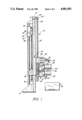
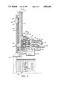
- FIG. 1 is a side elevational view of one embodiment of the subject assembly in partial cut-away.
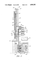
- FIG. 2 is a side elevation of the present invention in partial cut-away and shown in cooperative position relative to a molding machine.
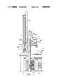
- FIG. 3 is a side elevation of the embodiments of FIGS. 1 and 2 in partial cut-away and phantom showing a different position of components of the subject assembly relative to the molding machine.
- FIG. 4 is a side elevation of the embodiments of FIGS. 1 through 3 in partial cut-away and phantom showing different positions of components of the subject assembly relative to the molding machine and a collection and recycling structure cooperatively disposed relative to the structure of the present invention.
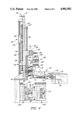
- FIG. 5 is a side elevation and partial cut-away and phantom of the embodiments of FIGS. 1 through 4 showing yet another position of the present invention.
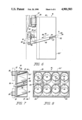
- FIG. 6 is a detail view in partial cut-away of one embodiment of the ejector assembly for removal of a runner structure from the plurality of plastic parts formed by the molding machine and its association with a collector assembly of the present invention.
- FIG. 7 is a sectional view in partial cut-away and phantom of the embodiment of the ejector assembly and its cooperative relation with the collector assembly.
- FIG. 8 is a front view of a receiving face of the collector assembly of the present invention as taken along line 8--8 of FIG. 7.
- Like reference numerals refer to like parts throughout the several views of the drawings.
- the assembly of the present invention is generally indicated as 10 and comprises an upstanding base 12 having an elongated substantially upright vertical orientation supported by a base plate structure 14 which is fixed to and mounted on a floor or other supporting member.
- the assembly comprises a collector means generally indicated as 16 including a collector housing 20 movably supported both vertically and transversely relative to the length of the base 12 as will be explained in greater detail hereinafter.
- the collector means 16 and more specifically the housing 20 is movably supported on the base 12 by a movable carriage generally indicated as 22.
- the carriage 22 is movable along the vertical length of the base 12 on support rods 24 and 24'.
- the carriage 22 may be pneumatically driven and may comprise an air cylinder 18.
- the carriage 22, in addition to the air cylinder 18, further includes a support portion 23 fixed to the cylinder 18 and further fixed to elongated upwardly extending arm member 25.
- the upper or distal portion of the arm member 25 is defined by an outwardly extending finger as at 25' which is disposed in lifting engagement with the upper end 27' of the bearing rods 27.
- the bearing or support or support rods 27 in fact move longitudinally of the base 12 with the carriage structure 22. Further, as shown in each of the FIGS.
- the collector means 16 including the housing 20 is fixed to move both vertically and transversely with the connector rods 27 due to a fixed interconnection therebetween as at 29 (see FIG. 7). Accordingly, as the carriage assembly 22, including the support portion 23, arm 25 and support or bearing rods 27 move vertically relative to the length of the base 12, so will the collector means 16 and housing 20 thereof so as to accomplish proper positioning of the collector housing 20 relative to the mold generally indicated as 100 as shown in FIGS. 2, 3, 4 and 5.
- the collector means 16 and housing 20 also moves transversely relative to the length of the base 12 and into and out of a parts receiving position relative to a parts issuing portion or face 101 of the mold 100. More specifically and also with reference to FIGS. 2 and 3, the collector housing 20, as set forth above, is fixed to and travels with the support and bearing rods 27 both vertically and transversely relative to base 12. As the carriage assembly 22 travels downwardly along the length of the base 12 and along the length of the support shafts 24 and 24', two roller cams 36, disposed on opposite sides of the support portion 23, are positioned to engage and pass into and along the length of elongated, angularly oriented receiving channels 38.
- the collector housing 20 is intended to travel both vertically and transversely along with the elongated support shafts 27, and further in that the support shafts 27 are connected to move transversely with the sub-assembly 40, each of the components including the sub-assembly 40, the support shafts 27 and the collector housing will move transversely in the direction indicated by directional arrows 41. This will bring the face 20' of the collector housing 20 into parts receiving relation to the mold face 101 from which the parts 110 and the runner 112 are ejected by a pushing mechanism generally indicated as 115 associated with the mold 100 as clearly shown in FIG. 3.
- the collector means 16 including the housing 20 comprises a plurality of open faces or open ended chambers 42 each designed to receive at least one part of an array of parts from the mold 100 as they issue in already separated relation from the face 101 thereof.
- the number of chambers 42 of course may vary and still be within the intended scope of the present invention. However, the actual number of chambers should be proportional to the number of parts issuing from the multi-cavity mold to insure that each part is placed within a separate chamber 42.
- each of the chambers 42 is disposed at a somewhat angular orientation relative to true horizontal. This orientation facilitates retaining of the individual parts in the chambers 42 and prevents or prevents or reduces the chance of inadvertent displacement of the parts from the respective chambers which may be caused by vibration of the subject assembly during its normal mode of operation.
- the position of the collector means including the collector housing 20 relative to the mold face 101 may define what is referred to herein as the parts receiving position wherein both the parts 110 and the runner 112, already having been separated, are received by the collector housing 20 directly from the mold 100.
- the mold 100 must in fact separate from its conventional molding position in order to expose mold face 101 and to lower and transversely orient the collector housing 20 into the receiving position shown in FIG. 3.
- the sequential steps of this vertical and transverse direction of travel of the collector housing 20 is shown consecutively in FIGS. 2 and 3.
- the carriage assembly 22 begins its upwardly vertical direction of travel.
- the roller cams 36 are forced upwardly through and along the length of the receiving channels 38. This will cause both an upward, vertical direction of travel of the housing 20 as well as an inward transverse direction of travel towards the base 12. Accordingly, the collector housing 20 will pass out of the parts receiving position relative to the mold face 101 as best shown in phantom lines in FIG. 4 and as noted in directional arrows 41' and 43.
- the subject invention further comprises an ejector assembly generally indicated as 50 and which is disposed and structured to effectively eject or "push" the runner structure 112 from its position generally adjacent the outer face 20' of the collector housing 20.
- an elongated arm 52 having its distal end as at 54 disposed in communicating relation to receiving slots 53 and 55 and any runner structure 112 contained therein.
- the slots 53 and 55 are disposed to receive the runner 112 therein as it is ejected or passes from the face 101 of the mold 100.
- the ejector means 50 When in such position and upon the upward travel of the collector housing 20, the ejector means 50 will be activated to cause an outward direction of travel of the ejector arm 52 in accordance with directional arrow 57. This in turn is accomplished by the interaction by the fixed elongated cam 63, having angled cam surface 63' fixedly positioned for abutting engagement with the roller cam rider 61 which in turn is attached to the pivot arm 56.
- the arm 56 is pivotally secured at one end 64 to a fixed brace as at 67 secured to the collector housing 20.
- the upward travel of the collector housing 20 forces the roller cam 61 into engagement with the cam surface 63' thereby forcing an outward direction of travel of the ejector arm 52.
- the distal end 54 then engages the runner 112 disposed within the slots 53 and 55 causing it to be ejected or kicked out into a runner receiver and recycling assembly generally indicated as 70.
- the collector housing 20 is at a level or vertical height on the base 12 such that the runner 112, once ejected, may fall into a receiving and recycling assembly 70 including a hopper 71. At this point, it is driven by compressed air or other applicable driving force along a conduct or like conveying structure 73 to a point where it may be re-ground (not shown for purposes of clarity) and eventually recycled once it is in a particulate material back to the plastic material supply for the mold 100.
- Directional arrows 75 track the path of travel of the runner 112 once it leaves the face or portion of the collector housing 20 to which it is secured after first being ejected from the face 101 of the mold 100.
- a runner structure 112 will not be produced, and accordingly, the aforementioned ejector means 50 will not be required or will be selectively rendered inoperative.
- a runner structure when a runner structure is produced and collected generally on the face 20' of the collector housing 20, it may be ejected into a receiving hopper for purposes of disposal rather than concurrent recycling thereof.
- it may be desired to use only "original" material. In such cases, the recycling of the collected runner, if such exists, would not be accomplished or alternately if recycling was in fact performed on the collected runner structure, the resulting recycled plastic material could be stored for a later, separate use.
- the carriage assembly 22 after ejection of the runner 112, continues its upward vertical travel along the base 12 as indicated by directional arrows 43 in FIG. 4. This will cause the collector means 16 and more specifically, the housing 20 to pass from the runner ejecting position as clearly defined in FIG. 4, upwardly into a delivery position relative to the delivery means generally indicated as 80.
- the delivery means comprises a plurality of separate conduits or tubular members as at 82 which may be formed of a flexible or like material.
- the receiving end as at 84 of each of the plurality of conveying conduits 82 is in aligned registered position with the open ends of the chambers 42 of the collector housing 20 such that the parts 110 (as clearly shown in FIG.
- each of the chambers 42 includes a first drive assembly including one or more nozzles 86 from which compressed air or like driving fluid issues.
- the compressed air blows the parts 110 from the chambers 42 of the collector housing 20, they pass along the length of the delivery conduits 82 to the distal end thereof wherein they are delivered to a plurality of storage and/or packaging containers as at 90.
- the directional arrows 85 and 87 are representative of the path of the driving pressurized fluid as they respectively enter the chambers 42 and the elongated delivery conduits 82.
- Pneumatic hoses or lines 89 represent a second drive assembly which is connected to the individual delivery conduits 82 for the delivery of pressurized air to the interior of the conduits for the driving force applied to the parts 110 as set forth above.
- Activation of a pressurized air supply to force the driving air into both the chambers 42 and the conduits 82 may be accomplished through the provision of a micro switch generally indicated as 93 disposed to engage the upper portion as at 25' of the support arm 25. Once so engaged, activation of the pressurized fluid supply will cause fluid to pass into both the chambers 42 and the conduits 82 in accordance with the aforementioned directional arrows 85 and 87 respectively.
Landscapes
- Engineering & Computer Science (AREA)
- Mechanical Engineering (AREA)
- Environmental & Geological Engineering (AREA)
- Manufacturing & Machinery (AREA)
- Moulds For Moulding Plastics Or The Like (AREA)
Abstract
Description
Claims (16)
Priority Applications (2)
| Application Number | Priority Date | Filing Date | Title |
|---|---|---|---|
| US07/217,358 US4901503A (en) | 1988-07-11 | 1988-07-11 | Apparatus for separating and packaging plastic parts |
| GB8915071A GB2220906A (en) | 1988-07-11 | 1989-06-30 | Apparatus for separating and packaging plastic parts. |
Applications Claiming Priority (1)
| Application Number | Priority Date | Filing Date | Title |
|---|---|---|---|
| US07/217,358 US4901503A (en) | 1988-07-11 | 1988-07-11 | Apparatus for separating and packaging plastic parts |
Publications (1)
| Publication Number | Publication Date |
|---|---|
| US4901503A true US4901503A (en) | 1990-02-20 |
Family
ID=22810740
Family Applications (1)
| Application Number | Title | Priority Date | Filing Date |
|---|---|---|---|
| US07/217,358 Expired - Fee Related US4901503A (en) | 1988-07-11 | 1988-07-11 | Apparatus for separating and packaging plastic parts |
Country Status (2)
| Country | Link |
|---|---|
| US (1) | US4901503A (en) |
| GB (1) | GB2220906A (en) |
Cited By (7)
| Publication number | Priority date | Publication date | Assignee | Title |
|---|---|---|---|---|
| US5329746A (en) * | 1990-01-18 | 1994-07-19 | Henri Vulliez | Device for packing protected articles for use in particular with foodstuffs into protective bags |
| US6146127A (en) * | 1998-12-31 | 2000-11-14 | Security Plastics, Inc. | Baffle sorting system for injection molding machines |
| US6155760A (en) * | 1999-05-03 | 2000-12-05 | Cannelli, Jr.; Victor | Workpiece receptacle for presses |
| US7204685B1 (en) | 2003-09-08 | 2007-04-17 | Crain Enterprises, Inc. | Modular mold |
| US7241405B1 (en) | 2003-09-08 | 2007-07-10 | Crain Enterprises, Inc. | Method of renewing a mold block |
| US20070286918A1 (en) * | 2004-09-08 | 2007-12-13 | Crain Enterprises, Inc. | Method of renewing a recyclable mold |
| US7497677B1 (en) | 2003-09-08 | 2009-03-03 | Crain Enterprises, Inc. | Mold having modular submold |
Families Citing this family (1)
| Publication number | Priority date | Publication date | Assignee | Title |
|---|---|---|---|---|
| DE10110225C2 (en) | 2001-03-02 | 2003-07-17 | Schott Glas | Glass-ceramic support material, process for its preparation and its use |
Citations (10)
| Publication number | Priority date | Publication date | Assignee | Title |
|---|---|---|---|---|
| US2995775A (en) * | 1957-12-26 | 1961-08-15 | Richardson Co | Injection molding |
| US3163470A (en) * | 1962-06-07 | 1964-12-29 | Corah St Margaret Ltd N | Pneumatic distributing system |
| US3207559A (en) * | 1962-08-23 | 1965-09-21 | Engineered Plastics Inc | Article collection system |
| US3246932A (en) * | 1959-03-09 | 1966-04-19 | Jr Roby B White | Coin conveyor |
| GB1039485A (en) * | 1964-04-29 | 1966-08-17 | Fives Lille Cail | Pneumatic separation installation |
| US3418694A (en) * | 1966-09-30 | 1968-12-31 | Pennsalt Chemicals Corp | Apparatus scrap grinder and plastic injection molding machine |
| US4045091A (en) * | 1972-08-26 | 1977-08-30 | Wolfgang Beneke | Device for the pneumatic feeding of a quantity of cards |
| US4067826A (en) * | 1974-07-31 | 1978-01-10 | Guy Emery | Recovery of mixed plastic materials |
| US4394259A (en) * | 1981-10-27 | 1983-07-19 | Temco, Inc. | Vacuum pneumatic conveying apparatus and method for transferring food products |
| US4422810A (en) * | 1978-12-20 | 1983-12-27 | Conair, Inc. | Apparatus for transporting pneumatically suspended particulates from a source to a plurality of receivers |
Family Cites Families (2)
| Publication number | Priority date | Publication date | Assignee | Title |
|---|---|---|---|---|
| DE1957546U (en) * | 1966-08-11 | 1967-03-23 | Gottfried Mehnert | ACCEPTANCE AND DISPENSING DEVICE FOR BLOWN BLOWED BODIES ON PLASTIC BLOW MACHINES. |
| US3729103A (en) * | 1971-02-16 | 1973-04-24 | Husky Mfg Tool Works Ltd | Transporter for molded parts and the like |
-
1988
- 1988-07-11 US US07/217,358 patent/US4901503A/en not_active Expired - Fee Related
-
1989
- 1989-06-30 GB GB8915071A patent/GB2220906A/en not_active Withdrawn
Patent Citations (10)
| Publication number | Priority date | Publication date | Assignee | Title |
|---|---|---|---|---|
| US2995775A (en) * | 1957-12-26 | 1961-08-15 | Richardson Co | Injection molding |
| US3246932A (en) * | 1959-03-09 | 1966-04-19 | Jr Roby B White | Coin conveyor |
| US3163470A (en) * | 1962-06-07 | 1964-12-29 | Corah St Margaret Ltd N | Pneumatic distributing system |
| US3207559A (en) * | 1962-08-23 | 1965-09-21 | Engineered Plastics Inc | Article collection system |
| GB1039485A (en) * | 1964-04-29 | 1966-08-17 | Fives Lille Cail | Pneumatic separation installation |
| US3418694A (en) * | 1966-09-30 | 1968-12-31 | Pennsalt Chemicals Corp | Apparatus scrap grinder and plastic injection molding machine |
| US4045091A (en) * | 1972-08-26 | 1977-08-30 | Wolfgang Beneke | Device for the pneumatic feeding of a quantity of cards |
| US4067826A (en) * | 1974-07-31 | 1978-01-10 | Guy Emery | Recovery of mixed plastic materials |
| US4422810A (en) * | 1978-12-20 | 1983-12-27 | Conair, Inc. | Apparatus for transporting pneumatically suspended particulates from a source to a plurality of receivers |
| US4394259A (en) * | 1981-10-27 | 1983-07-19 | Temco, Inc. | Vacuum pneumatic conveying apparatus and method for transferring food products |
Cited By (8)
| Publication number | Priority date | Publication date | Assignee | Title |
|---|---|---|---|---|
| US5329746A (en) * | 1990-01-18 | 1994-07-19 | Henri Vulliez | Device for packing protected articles for use in particular with foodstuffs into protective bags |
| US6146127A (en) * | 1998-12-31 | 2000-11-14 | Security Plastics, Inc. | Baffle sorting system for injection molding machines |
| US6155760A (en) * | 1999-05-03 | 2000-12-05 | Cannelli, Jr.; Victor | Workpiece receptacle for presses |
| US7204685B1 (en) | 2003-09-08 | 2007-04-17 | Crain Enterprises, Inc. | Modular mold |
| US7241405B1 (en) | 2003-09-08 | 2007-07-10 | Crain Enterprises, Inc. | Method of renewing a mold block |
| US7497677B1 (en) | 2003-09-08 | 2009-03-03 | Crain Enterprises, Inc. | Mold having modular submold |
| US20070286918A1 (en) * | 2004-09-08 | 2007-12-13 | Crain Enterprises, Inc. | Method of renewing a recyclable mold |
| US7500843B2 (en) | 2004-09-08 | 2009-03-10 | Crain Enterprises, Inc. | Mold system kit |
Also Published As
| Publication number | Publication date |
|---|---|
| GB2220906A (en) | 1990-01-24 |
| GB8915071D0 (en) | 1989-08-23 |
Similar Documents
| Publication | Publication Date | Title |
|---|---|---|
| US5650110A (en) | Method for thermoforming and stacking hollow objects | |
| US10343852B2 (en) | Device and method for delivering oriented elements | |
| US7690883B2 (en) | Pivoting basket stacker for deep-drawn articles | |
| US4901503A (en) | Apparatus for separating and packaging plastic parts | |
| US5407339A (en) | Triturate tablet machine | |
| CA1097279A (en) | Apparatus for filling containers with articles | |
| JPH03126520A (en) | Device and method for applying label on mold of plastic blow molder | |
| US6851920B2 (en) | Method for stacking parts comprising thermoplastic plastic, and apparatus for executing the method | |
| EP0957028A1 (en) | Method for packaging articles into containers | |
| EP0516072A2 (en) | Molded bottle removal apparatus and method | |
| DE69603693T2 (en) | Insert molding system | |
| US5439634A (en) | Method and device for separating runners/sprues from parts as they are ejected from a mold | |
| EP1201574A1 (en) | Method and device for piling parts made of thermoplastic material | |
| DE69804868T2 (en) | DEVICE FOR THE SEQUENTIAL TRANSPORTATION OF BOTTLES OF PLASTIC MATERIAL | |
| US6146127A (en) | Baffle sorting system for injection molding machines | |
| KR100231621B1 (en) | Handling device for layered cellulose products, in particular cotton wool pads | |
| CN214570585U (en) | Automatic buckling equipment for cup cover | |
| US3792955A (en) | Article transfer apparatus | |
| CN220594018U (en) | Plastic bottle shaping packaging production line | |
| US20050093207A1 (en) | Injection molding lid transfer apparatus and method | |
| EP4046916A1 (en) | Method and device for forming packaging stacks | |
| CN115367200A (en) | Molding container packing line | |
| GB2445933A (en) | Handling system for moulded parts | |
| JPS6144733B2 (en) | ||
| JPH08175661A (en) | Vessel aligning device |
Legal Events
| Date | Code | Title | Description |
|---|---|---|---|
| AS | Assignment |
Owner name: SECURITY PLASTICS, INC., 14427 N.W. 60TH AVE., MIA Free format text: ASSIGNMENT OF ASSIGNORS INTEREST.;ASSIGNORS:GOMEZ, ENIDIO A.;DOWNEY, ROBERT J.;REEL/FRAME:004953/0988 Effective date: 19880707 Owner name: SECURITY PLASTICS, INC.,FLORIDA Free format text: ASSIGNMENT OF ASSIGNORS INTEREST;ASSIGNORS:GOMEZ, ENIDIO A.;DOWNEY, ROBERT J.;REEL/FRAME:004953/0988 Effective date: 19880707 |
|
| FPAY | Fee payment |
Year of fee payment: 4 |
|
| FPAY | Fee payment |
Year of fee payment: 8 |
|
| REMI | Maintenance fee reminder mailed | ||
| LAPS | Lapse for failure to pay maintenance fees | ||
| AS | Assignment |
Owner name: SP DIVISION-NMC, LLC, FLORIDA Free format text: ASSIGNMENT OF ASSIGNORS INTEREST;ASSIGNOR:SECURITY PLASTICS, INC.;REEL/FRAME:012745/0640 Effective date: 20020207 Owner name: SECURITY PLASTICS DIVISION/NMC, LLC, FLORIDA Free format text: CHANGE OF NAME;ASSIGNOR:SP DIVISION-NMC, LLC;REEL/FRAME:012745/0656 Effective date: 20020226 |
|
| LAPS | Lapse for failure to pay maintenance fees |
Free format text: PATENT EXPIRED FOR FAILURE TO PAY MAINTENANCE FEES (ORIGINAL EVENT CODE: EXP.); ENTITY STATUS OF PATENT OWNER: SMALL ENTITY |
|
| STCH | Information on status: patent discontinuation |
Free format text: PATENT EXPIRED DUE TO NONPAYMENT OF MAINTENANCE FEES UNDER 37 CFR 1.362 |
|
| AS | Assignment |
Owner name: JP MORGAN CHASE BANK, NEW YORK Free format text: SECURITY INTEREST;ASSIGNOR:SP DIVISION-NMC, LLC;REEL/FRAME:012785/0072 Effective date: 20020205 |
|
| FP | Lapsed due to failure to pay maintenance fee |
Effective date: 20020220 |
|
| AS | Assignment |
Owner name: NATIONAL MOLDING, LLC, FLORIDA Free format text: ASSIGNMENT OF ASSIGNORS INTEREST;ASSIGNOR:SECURITY PLASTICS;REEL/FRAME:021398/0761 Effective date: 20080701 |
|
| AS | Assignment |
Owner name: TEXAS CAPITAL BANK, NATIONAL ASSOCIATION, TEXAS Free format text: SECURITY AGREEMENT;ASSIGNOR:NATIONAL MOLDING, LLC;REEL/FRAME:029990/0001 Effective date: 20130311 |