US4901497A - Fastener for form panels - Google Patents
Fastener for form panels Download PDFInfo
- Publication number
- US4901497A US4901497A US07/370,851 US37085189A US4901497A US 4901497 A US4901497 A US 4901497A US 37085189 A US37085189 A US 37085189A US 4901497 A US4901497 A US 4901497A
- Authority
- US
- United States
- Prior art keywords
- rod portion
- back face
- opposed
- insert rod
- face
- Prior art date
- Legal status (The legal status is an assumption and is not a legal conclusion. Google has not performed a legal analysis and makes no representation as to the accuracy of the status listed.)
- Expired - Fee Related
Links
- 229910000831 Steel Inorganic materials 0.000 description 3
- 230000000712 assembly Effects 0.000 description 3
- 238000000429 assembly Methods 0.000 description 3
- 239000010959 steel Substances 0.000 description 3
- 230000015572 biosynthetic process Effects 0.000 description 1
- 238000012986 modification Methods 0.000 description 1
- 230000004048 modification Effects 0.000 description 1
- 239000011120 plywood Substances 0.000 description 1
- 230000003014 reinforcing effect Effects 0.000 description 1
Images

Classifications
-
- E—FIXED CONSTRUCTIONS
- E04—BUILDING
- E04G—SCAFFOLDING; FORMS; SHUTTERING; BUILDING IMPLEMENTS OR AIDS, OR THEIR USE; HANDLING BUILDING MATERIALS ON THE SITE; REPAIRING, BREAKING-UP OR OTHER WORK ON EXISTING BUILDINGS
- E04G17/00—Connecting or other auxiliary members for forms, falsework structures, or shutterings
- E04G17/14—Bracing or strutting arrangements for formwalls; Devices for aligning forms
-
- E—FIXED CONSTRUCTIONS
- E04—BUILDING
- E04F—FINISHING WORK ON BUILDINGS, e.g. STAIRS, FLOORS
- E04F21/00—Implements for finishing work on buildings
-
- E—FIXED CONSTRUCTIONS
- E04—BUILDING
- E04G—SCAFFOLDING; FORMS; SHUTTERING; BUILDING IMPLEMENTS OR AIDS, OR THEIR USE; HANDLING BUILDING MATERIALS ON THE SITE; REPAIRING, BREAKING-UP OR OTHER WORK ON EXISTING BUILDINGS
- E04G17/00—Connecting or other auxiliary members for forms, falsework structures, or shutterings
- E04G17/04—Connecting or fastening means for metallic forming or stiffening elements, e.g. for connecting metallic elements to non-metallic elements
-
- Y—GENERAL TAGGING OF NEW TECHNOLOGICAL DEVELOPMENTS; GENERAL TAGGING OF CROSS-SECTIONAL TECHNOLOGIES SPANNING OVER SEVERAL SECTIONS OF THE IPC; TECHNICAL SUBJECTS COVERED BY FORMER USPC CROSS-REFERENCE ART COLLECTIONS [XRACs] AND DIGESTS
- Y10—TECHNICAL SUBJECTS COVERED BY FORMER USPC
- Y10T—TECHNICAL SUBJECTS COVERED BY FORMER US CLASSIFICATION
- Y10T403/00—Joints and connections
- Y10T403/57—Distinct end coupler
Definitions
- This invention relates to a fastener for a form assembly and particularly to a fastener which includes looped members and key members to be inserted in the looped members.
- a typical steel ply form panel includes a rectangular plywood facing secured to a rectangular steel reinforcing frame which includes vertical and horizontal bars projecting rearward from the form panel.
- the sides of the panel are bounded by two parallel vertical bars which are used to be connected to the vertical members of other form panels.
- vertical bars are abutted against one another and fastened to one another by means of wedge bolts each of which are inserted tightly in a slot of a cross piece which is threaded through two aligned slots of abutting bars.
- An object of the invention is to provide a form panel fastener which connect two edge-to-edge adjacent panel facings of adjacent modular panel units, thereby minimizing the creation of clearances between adjacent panel units.
- the present invention provides a fastening device to fasten at least two edge-to-edge contiguous panel facings each of which has two opposite longitudinal sides, two opposite transverse sides and a back face.
- the fastening device includes a plurality of looped members projecting from the back face of each of the panel facings along the longitudinal sides thereof, the looped members of one of the panel facings being respectively aligned with the looped members of an adjacent the panel facing, each looped member having an engagement face spaced parallely from the back face of the panel facing and two opposed flanks extending from two sides of the engagement face of the looped member and connected to the back face. The distance between the flanks is greater than that between the engagement face and the back face.
- Each key member to be inserted into the looped members has an insert rod portion to be inserted in at least two aligned looped members and a handle rod portion which forms an angle with the insert rod portion.
- the insert rod portion has a pair of first opposed longitudinal faces, and a pair of second opposed longitudinal faces. The distance between the first opposed faces is smaller than the distance between the engagement face and the back face so that the insert rod portion can be inserted into aligned looped members. The distance between the second opposed faces is greater than the distance between the engagement face and the back face so that the second opposed faces are engaged respectively with the engagement face and the back face when the insert rod portion is turned an angle after being inserted.
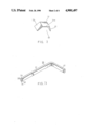
- FIG. 1 is a perspective view of two panel facings which are provided with fasteners of the present invention
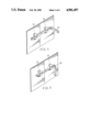
- FIG. 2 shows a looped member of a fastener according to the present invention
- FIG. 3 is a key member to be inserted into the looped member
- FIGS. 4 and 5 show how the panel facings are fastened by the looped member and key member
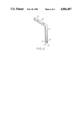
- FIG. 6 shows an alternative form of the key member.
- a fastening device embodying the present invention is used for fastening two adjacent panel facings 10 each of which will be connected a backing frame to constitute a form panel unit.
- the backing frame is detachably connected to the panel facings.
- the type of form panel unit is disclosed in a copending application of the inventor of the application.
- the fastening device includes a plurality of looped members 20 provided along adjacent longitudinal sides of the panel facing 10 and a plurality of key members 30 to be inserted in the looped members 20.
- the looped members 20 on one of the panel facings 10 are respectively aligned with the looped members 20 on the adjacent panel facing 10.
- Each looped member 20 has a substantially planar engagement member 21 with an inner engagement face 21a and two flanks 22, 23 which are welded to the back face of each panel facing.
- the engagement member 21 and the flanks 22, 23 of each looped member confine an opening with the back face of the panel facing.
- the fastener means to fasten the form panels also includes key members 30 each having an insert rod portion 31 to be inserted in two aligned looped members 20 and a handle rod portion 32 which forms an angle with the insert rod portion 31.
- the insert rod portion 31 has a substantially rectangular cross-section and has both a pair of first opposed longitudinal faces 33 and a pair of second opposed longitudinal faces 34. The length between the first opposed faces 33 is smaller than that between the engagement face 21a and the back face of the panel facing 10 so that the insert rod portion 31 can be inserted into the aligned looped members 20.
- the length between the second opposed faces 34 is greater than that between the engagement face 21a and the back face of the panel facing 10 so that the faces 34 engage respectively with the engagement face 21a of the looped member 20 and the back face of the panel facing 10 when the insert rod portion 31 is turned 90 deg after being inserted.
- the opposed faces 34 are slightly convexed so that the key member 30 can be turned smoothly.
- two panel facings are arranged in edge-to-edge contiguity and the looped members are aligned respectively.
- the key members 30 are inserted into the aligned looped members 20 and then turned 90 deg to cause the insert rod portions of the key members to engage tightly with the looped member, thereby fastening the panel facings 10.
- the panel facings are made of a steel plate having a thickness of 4 mm and a dimension of 3400 ⁇ 1260 sq.mm.
- the distance between two adjacent looped members is arranged to be about 100 mm.
- the insert rod portion of the key member 30 is longer than the handle portion, and the handle portion is turned to be in contact with the panel facing 10 when the key member is locked in the looped member.
- This fastener is suitable for fastening vertical panel facings.
- an alternative key 40 has a handle portion 41 which is longer than the insert portion 42 thereof.
- the key 40 also has a rectangular cross-section, being formed with two opposed engaging faces 44 and another two opposed faces 43.
- the engaging faces 44 will engage with the engagement face of the looped member and the back face of the panel facing when the key member 40 is in a locked position.
- the difference between the key members 30 and 40 is that the handle portion 41 projects from the panel facing 10 downwardly when in the locked position.
- This form is suitable for fastening panel facings to be arranged horizontally during the formation of a ceiling so that an operator can conveniently operate the key member 40 below the form.
Landscapes
- Engineering & Computer Science (AREA)
- Architecture (AREA)
- Civil Engineering (AREA)
- Structural Engineering (AREA)
- Mechanical Engineering (AREA)
- Connection Of Plates (AREA)
- Forms Removed On Construction Sites Or Auxiliary Members Thereof (AREA)
- Floor Finish (AREA)
- Conveying And Assembling Of Building Elements In Situ (AREA)
- Roof Covering Using Slabs Or Stiff Sheets (AREA)
- Joining Of Building Structures In Genera (AREA)
Abstract
A fastening device to fasten at least two edge-to-edge contiguous panel facings includes a plurality of looped members projecting from the back face of each panel facing along the longitudinal sides thereof. Each looped member has an engagement face spaced parallely from the back face and two opposed angled flanks connected to the back face. Key members are to be inserted into the looped members, each having an insert rod portion and a handle rod portion which forms an angle with the insert rod portion, the insert rod portion having a pair of first opposed longitudinal faces, and a pair of second opposed longitudinal faces. The distance between the first opposed faces is smaller than the distance between the engagement face and the back face so that the insert rod portion can be inserted into two aligned looped members, and the distance between the second opposed faces is greater than the distance between the engagement face and the back face. The second opposed faces engage with the engagement face and the back face when the insert rod portion is turned an angle after being inserted.
Description
This invention relates to a fastener for a form assembly and particularly to a fastener which includes looped members and key members to be inserted in the looped members.
It is now a common practice to assemble modular form panels into a large form board which can be stripped entirely from a formed concrete structure and which can be used repeatedly to form similar concrete structures without the need to dissemble and reassemble the form board. Various kinds of fasteners are provided to fasten panel units which constitute form assemblies in the art. In most of the known form assemblies, form panel units are interconnected by means of fasteners or connectors which are provided at adjacent backing members rather than on the panel facing of the form assemblies. For example, a typical steel ply form panel includes a rectangular plywood facing secured to a rectangular steel reinforcing frame which includes vertical and horizontal bars projecting rearward from the form panel. The sides of the panel are bounded by two parallel vertical bars which are used to be connected to the vertical members of other form panels. In such a kind of form panel, vertical bars are abutted against one another and fastened to one another by means of wedge bolts each of which are inserted tightly in a slot of a cross piece which is threaded through two aligned slots of abutting bars.
An object of the invention is to provide a form panel fastener which connect two edge-to-edge adjacent panel facings of adjacent modular panel units, thereby minimizing the creation of clearances between adjacent panel units.
The present invention provides a fastening device to fasten at least two edge-to-edge contiguous panel facings each of which has two opposite longitudinal sides, two opposite transverse sides and a back face. The fastening device includes a plurality of looped members projecting from the back face of each of the panel facings along the longitudinal sides thereof, the looped members of one of the panel facings being respectively aligned with the looped members of an adjacent the panel facing, each looped member having an engagement face spaced parallely from the back face of the panel facing and two opposed flanks extending from two sides of the engagement face of the looped member and connected to the back face. The distance between the flanks is greater than that between the engagement face and the back face. Each key member to be inserted into the looped members has an insert rod portion to be inserted in at least two aligned looped members and a handle rod portion which forms an angle with the insert rod portion. The insert rod portion has a pair of first opposed longitudinal faces, and a pair of second opposed longitudinal faces. The distance between the first opposed faces is smaller than the distance between the engagement face and the back face so that the insert rod portion can be inserted into aligned looped members. The distance between the second opposed faces is greater than the distance between the engagement face and the back face so that the second opposed faces are engaged respectively with the engagement face and the back face when the insert rod portion is turned an angle after being inserted.
The present exemplary preferred embodiment will be described in detail with reference to the accompanying drawings, in which:
FIG. 1 is a perspective view of two panel facings which are provided with fasteners of the present invention;
FIG. 2 shows a looped member of a fastener according to the present invention;
FIG. 3 is a key member to be inserted into the looped member;
FIGS. 4 and 5 show how the panel facings are fastened by the looped member and key member; and
FIG. 6 shows an alternative form of the key member.
Referring to the drawings, a fastening device embodying the present invention is used for fastening two adjacent panel facings 10 each of which will be connected a backing frame to constitute a form panel unit. The backing frame is detachably connected to the panel facings. The type of form panel unit is disclosed in a copending application of the inventor of the application.
The fastening device includes a plurality of looped members 20 provided along adjacent longitudinal sides of the panel facing 10 and a plurality of key members 30 to be inserted in the looped members 20. The looped members 20 on one of the panel facings 10 are respectively aligned with the looped members 20 on the adjacent panel facing 10.
Each looped member 20 has a substantially planar engagement member 21 with an inner engagement face 21a and two flanks 22, 23 which are welded to the back face of each panel facing. The engagement member 21 and the flanks 22, 23 of each looped member confine an opening with the back face of the panel facing.
The fastener means to fasten the form panels also includes key members 30 each having an insert rod portion 31 to be inserted in two aligned looped members 20 and a handle rod portion 32 which forms an angle with the insert rod portion 31. The insert rod portion 31 has a substantially rectangular cross-section and has both a pair of first opposed longitudinal faces 33 and a pair of second opposed longitudinal faces 34. The length between the first opposed faces 33 is smaller than that between the engagement face 21a and the back face of the panel facing 10 so that the insert rod portion 31 can be inserted into the aligned looped members 20. The length between the second opposed faces 34 is greater than that between the engagement face 21a and the back face of the panel facing 10 so that the faces 34 engage respectively with the engagement face 21a of the looped member 20 and the back face of the panel facing 10 when the insert rod portion 31 is turned 90 deg after being inserted. Preferably, the opposed faces 34 are slightly convexed so that the key member 30 can be turned smoothly.
In operation, two panel facings are arranged in edge-to-edge contiguity and the looped members are aligned respectively. The key members 30 are inserted into the aligned looped members 20 and then turned 90 deg to cause the insert rod portions of the key members to engage tightly with the looped member, thereby fastening the panel facings 10.
Preferably, the panel facings are made of a steel plate having a thickness of 4 mm and a dimension of 3400×1260 sq.mm. The distance between two adjacent looped members is arranged to be about 100 mm.
As shown in FIGS. 4 and 5, the insert rod portion of the key member 30 is longer than the handle portion, and the handle portion is turned to be in contact with the panel facing 10 when the key member is locked in the looped member. This fastener is suitable for fastening vertical panel facings.
As shown in FIG. 5 an alternative key 40 has a handle portion 41 which is longer than the insert portion 42 thereof. The key 40 also has a rectangular cross-section, being formed with two opposed engaging faces 44 and another two opposed faces 43. The engaging faces 44 will engage with the engagement face of the looped member and the back face of the panel facing when the key member 40 is in a locked position. The difference between the key members 30 and 40 is that the handle portion 41 projects from the panel facing 10 downwardly when in the locked position. This form is suitable for fastening panel facings to be arranged horizontally during the formation of a ceiling so that an operator can conveniently operate the key member 40 below the form.
With the invention thus explained, it is apparent that various modifications and variations can be made without departing from the scope of the invention. It is therefore intended that the invention be limited only as indicated in the appended claims.
Claims (2)
1. A fastening device to fasten at least two edge-to-edge contiguous panel facings each of which has two opposite longitudinal sides, two opposite transverse sides and a back face, comprising
a plurality of looped members projecting from said back face of each of the panel facings along said longitudinal sides, said looped members of one of said panel facings being respectively aligned with said looped members of an adjacent said panel facing, each of said looped members having an engagement face spaced parallely from said back face and two opposed flanks extending from two sides of said engagement face and being connected to said back face, the distance between said flanks being greater than that between said engagement face and said back face, and key members each having an insert rod portion to be inserted in at least two aligned said looped members and a handle rod portion which forms an angle with said insert rod portion, said insert rod portion having a pair of first opposed longitudinal faces, and a pair of second opposed longitudinal faces, the distance between said first opposed faces being smaller than the distance between said engagement face and said back face so that said insert rod portion can be inserted into aligned said looped members, the distance between said second opposed faces being greater than the distance between said first opposed faces, said second opposed faces being engaged respectively with said engagement face and said back face when said insert rod portion is turned a certain angle after being inserted.
2. A fastening device as claimed in claim 1, wherein said insert rod portion has a substantially rectangular cross-section, and said second opposed faces are slightly convexed.
Priority Applications (15)
| Application Number | Priority Date | Filing Date | Title |
|---|---|---|---|
| US07/370,851 US4901497A (en) | 1989-06-23 | 1989-06-23 | Fastener for form panels |
| EP90306675A EP0404514B1 (en) | 1989-06-23 | 1990-06-19 | Fastener for form panels |
| DK90306675.1T DK0404514T3 (en) | 1989-06-23 | 1990-06-19 | Fastening device for formwork plates |
| PL90285687A PL165562B1 (en) | 1989-06-23 | 1990-06-19 | Unit for connecting panels |
| PE1990170961A PE8291A1 (en) | 1989-06-23 | 1990-06-19 | FASTENERS FOR STRUCTURED PANELS |
| AU57630/90A AU603978B3 (en) | 1989-06-23 | 1990-06-19 | Fastener for form panels |
| AT90306675T ATE88788T1 (en) | 1989-06-23 | 1990-06-19 | CONNECTING ELEMENT FOR FORMWORK PANELS. |
| DE90306675T DE69001460T2 (en) | 1989-06-23 | 1990-06-19 | Connection element for formwork panels. |
| CN90209069U CN2067304U (en) | 1989-06-23 | 1990-06-19 | Combining device for steel formwork panels for construction |
| ES199090306675T ES2041508T3 (en) | 1989-06-23 | 1990-06-19 | A COMBINATION OF FIXING DEVICE AND PANEL BOARDS. |
| BR909002908A BR9002908A (en) | 1989-06-23 | 1990-06-20 | FASTENING DEVICE FOR SHAPED PANELS |
| AR90317169A AR248169A1 (en) | 1989-06-23 | 1990-06-20 | Fastener for form panels |
| MX021254A MX167232B (en) | 1989-06-23 | 1990-06-20 | PATTERN PANEL HOLDER |
| CA002019429A CA2019429C (en) | 1989-06-23 | 1990-06-20 | Fastener for form panels |
| SU904830333A RU2068480C1 (en) | 1989-06-23 | 1990-06-22 | Clamp device |
Applications Claiming Priority (1)
| Application Number | Priority Date | Filing Date | Title |
|---|---|---|---|
| US07/370,851 US4901497A (en) | 1989-06-23 | 1989-06-23 | Fastener for form panels |
Publications (1)
| Publication Number | Publication Date |
|---|---|
| US4901497A true US4901497A (en) | 1990-02-20 |
Family
ID=23461456
Family Applications (1)
| Application Number | Title | Priority Date | Filing Date |
|---|---|---|---|
| US07/370,851 Expired - Fee Related US4901497A (en) | 1989-06-23 | 1989-06-23 | Fastener for form panels |
Country Status (15)
| Country | Link |
|---|---|
| US (1) | US4901497A (en) |
| EP (1) | EP0404514B1 (en) |
| CN (1) | CN2067304U (en) |
| AR (1) | AR248169A1 (en) |
| AT (1) | ATE88788T1 (en) |
| AU (1) | AU603978B3 (en) |
| BR (1) | BR9002908A (en) |
| CA (1) | CA2019429C (en) |
| DE (1) | DE69001460T2 (en) |
| DK (1) | DK0404514T3 (en) |
| ES (1) | ES2041508T3 (en) |
| MX (1) | MX167232B (en) |
| PE (1) | PE8291A1 (en) |
| PL (1) | PL165562B1 (en) |
| RU (1) | RU2068480C1 (en) |
Cited By (15)
| Publication number | Priority date | Publication date | Assignee | Title |
|---|---|---|---|---|
| AU667794B3 (en) * | 1995-08-18 | 1996-04-04 | Kou-An Lee | Modular wall form assembly |
| US5544852A (en) * | 1995-01-18 | 1996-08-13 | Lee; Wen-Yuan | Modular form assembly for concrete structure |
| US5552103A (en) * | 1995-01-18 | 1996-09-03 | Lee; Wen-Yuan | Form set-up and method for stripping upright form panels of the form set-up from a concrete unit |
| US5651913A (en) * | 1995-01-18 | 1997-07-29 | Lee; Wen-Yuan | Modular form assembly for concrete structure |
| FR2745840A1 (en) * | 1995-08-08 | 1997-09-12 | Lee Wen Yuan | SUPPORT DEVICE FOR FLOOR FORM MOUNTING |
| US5695676A (en) * | 1995-01-18 | 1997-12-09 | Lee; Wen-Yuan | Modular form assembly for concrete structures |
| US5700106A (en) * | 1996-03-12 | 1997-12-23 | Young; James E. | Island form |
| US5802795A (en) * | 1997-11-14 | 1998-09-08 | Feather Lite Innovations, Inc. | Self-retaining pin for concrete wall panels |
| US6010276A (en) * | 1996-03-12 | 2000-01-04 | Young; James E. | Island form |
| US20050120663A1 (en) * | 2003-12-03 | 2005-06-09 | Geoplast S.P.A. | Re-usable modular formwork with improved ribs |
| US20090113828A1 (en) * | 2007-11-01 | 2009-05-07 | Radu Jr John | Galvannealed steel forms |
| US20110194893A1 (en) * | 2010-02-05 | 2011-08-11 | Open Range Energy Corp. | Container fastening assembly |
| USD766751S1 (en) * | 2013-02-24 | 2016-09-20 | Custom Glass Products Of Carolina, Inc. | Gauge with handle |
| JP2019203312A (en) * | 2018-05-24 | 2019-11-28 | 株式会社ダイケン | Junction structure for form panel, concrete construction method of form panel and floor inspection hole |
| USD915874S1 (en) * | 2020-08-12 | 2021-04-13 | Frank Locatell | Removable form tie |
Families Citing this family (4)
| Publication number | Priority date | Publication date | Assignee | Title |
|---|---|---|---|---|
| CN103541546A (en) * | 2013-09-27 | 2014-01-29 | 广东一百建筑科技有限公司 | Device for rapidly mounting and demounting building formworks |
| CN105804524A (en) * | 2016-03-24 | 2016-07-27 | 刘影 | Icehouse sealing door latch mechanism |
| CN106382006B (en) * | 2016-08-31 | 2018-07-24 | 赣州市嘉班钢模有限公司 | A kind of arch chuck and the method using the progress template installation of arch chuck |
| KR102848254B1 (en) * | 2023-03-10 | 2025-08-21 | 권오영 | a construction method of a building structure and the building structure |
Citations (4)
| Publication number | Priority date | Publication date | Assignee | Title |
|---|---|---|---|---|
| US2863683A (en) * | 1955-12-20 | 1958-12-09 | Rome Cable Corp | Connecting means |
| US3244248A (en) * | 1961-07-26 | 1966-04-05 | Westland Aircraft Ltd | Vehicles |
| US3986315A (en) * | 1975-11-07 | 1976-10-19 | Diamond Power Specialty Corporation | Adjustable height insulation panel |
| DE3017103A1 (en) * | 1980-01-28 | 1981-11-19 | Petz Electro, 3185 Schmitten | ARRANGEMENT FOR CONNECTING THE EDGE AREAS OF COMBINED THIN-WALLED BODIES |
Family Cites Families (4)
| Publication number | Priority date | Publication date | Assignee | Title |
|---|---|---|---|---|
| US1350084A (en) * | 1917-11-13 | 1920-08-17 | Charles H Schub | Clamp |
| US1552334A (en) * | 1923-10-13 | 1925-09-01 | Edgar H Mosher | Concrete-form clamp |
| US3751790A (en) * | 1970-10-05 | 1973-08-14 | S Frazier | Construction of a form for concrete molding |
| FR2615554B3 (en) * | 1987-05-22 | 1989-09-29 | Gendrot Fernand | DEVICE FOR ASSEMBLING TWO PARTS, PARTICULARLY A FORMWORK PANEL AND A STABILIZER FOR THIS PANEL |
-
1989
- 1989-06-23 US US07/370,851 patent/US4901497A/en not_active Expired - Fee Related
-
1990
- 1990-06-19 AU AU57630/90A patent/AU603978B3/en not_active Ceased
- 1990-06-19 ES ES199090306675T patent/ES2041508T3/en not_active Expired - Lifetime
- 1990-06-19 DE DE90306675T patent/DE69001460T2/en not_active Expired - Fee Related
- 1990-06-19 PL PL90285687A patent/PL165562B1/en unknown
- 1990-06-19 DK DK90306675.1T patent/DK0404514T3/en active
- 1990-06-19 EP EP90306675A patent/EP0404514B1/en not_active Expired - Lifetime
- 1990-06-19 PE PE1990170961A patent/PE8291A1/en unknown
- 1990-06-19 CN CN90209069U patent/CN2067304U/en not_active Expired - Lifetime
- 1990-06-19 AT AT90306675T patent/ATE88788T1/en active
- 1990-06-20 CA CA002019429A patent/CA2019429C/en not_active Expired - Fee Related
- 1990-06-20 BR BR909002908A patent/BR9002908A/en not_active IP Right Cessation
- 1990-06-20 MX MX021254A patent/MX167232B/en unknown
- 1990-06-20 AR AR90317169A patent/AR248169A1/en active
- 1990-06-22 RU SU904830333A patent/RU2068480C1/en active
Patent Citations (4)
| Publication number | Priority date | Publication date | Assignee | Title |
|---|---|---|---|---|
| US2863683A (en) * | 1955-12-20 | 1958-12-09 | Rome Cable Corp | Connecting means |
| US3244248A (en) * | 1961-07-26 | 1966-04-05 | Westland Aircraft Ltd | Vehicles |
| US3986315A (en) * | 1975-11-07 | 1976-10-19 | Diamond Power Specialty Corporation | Adjustable height insulation panel |
| DE3017103A1 (en) * | 1980-01-28 | 1981-11-19 | Petz Electro, 3185 Schmitten | ARRANGEMENT FOR CONNECTING THE EDGE AREAS OF COMBINED THIN-WALLED BODIES |
Cited By (23)
| Publication number | Priority date | Publication date | Assignee | Title |
|---|---|---|---|---|
| US5544852A (en) * | 1995-01-18 | 1996-08-13 | Lee; Wen-Yuan | Modular form assembly for concrete structure |
| US5552103A (en) * | 1995-01-18 | 1996-09-03 | Lee; Wen-Yuan | Form set-up and method for stripping upright form panels of the form set-up from a concrete unit |
| US5651913A (en) * | 1995-01-18 | 1997-07-29 | Lee; Wen-Yuan | Modular form assembly for concrete structure |
| US5695676A (en) * | 1995-01-18 | 1997-12-09 | Lee; Wen-Yuan | Modular form assembly for concrete structures |
| FR2745840A1 (en) * | 1995-08-08 | 1997-09-12 | Lee Wen Yuan | SUPPORT DEVICE FOR FLOOR FORM MOUNTING |
| FR2745837A1 (en) * | 1995-08-08 | 1997-09-12 | Lee Wen Yuan | SHAPE CONTRACTION DEVICE FOR FLOOR SHAPE MOUNTING |
| US5676874A (en) * | 1995-08-08 | 1997-10-14 | Lee; Wen-Yuan | Floor form assembly and apparatus used therewith |
| GB2304140B (en) * | 1995-08-08 | 1999-07-28 | Lee Wen Yuan | Floor form assembly |
| US5609323A (en) * | 1995-08-18 | 1997-03-11 | Lee; Kou-An | Modular wall form assembly |
| AU667794B3 (en) * | 1995-08-18 | 1996-04-04 | Kou-An Lee | Modular wall form assembly |
| US6010276A (en) * | 1996-03-12 | 2000-01-04 | Young; James E. | Island form |
| US5700106A (en) * | 1996-03-12 | 1997-12-23 | Young; James E. | Island form |
| US5802795A (en) * | 1997-11-14 | 1998-09-08 | Feather Lite Innovations, Inc. | Self-retaining pin for concrete wall panels |
| US20050120663A1 (en) * | 2003-12-03 | 2005-06-09 | Geoplast S.P.A. | Re-usable modular formwork with improved ribs |
| US7469873B2 (en) * | 2003-12-03 | 2008-12-30 | Geoplast S.P.A. | Re-usable modular formwork with improved ribs |
| US20090113828A1 (en) * | 2007-11-01 | 2009-05-07 | Radu Jr John | Galvannealed steel forms |
| US7950872B2 (en) * | 2007-11-01 | 2011-05-31 | Radu Jr John | Galvannealed steel forms |
| US20110186710A1 (en) * | 2007-11-01 | 2011-08-04 | Radu Jr John | Galvannealed steel forms |
| US9328469B2 (en) | 2007-11-01 | 2016-05-03 | John Radu, Jr. | Galvannealed steel forms |
| US20110194893A1 (en) * | 2010-02-05 | 2011-08-11 | Open Range Energy Corp. | Container fastening assembly |
| USD766751S1 (en) * | 2013-02-24 | 2016-09-20 | Custom Glass Products Of Carolina, Inc. | Gauge with handle |
| JP2019203312A (en) * | 2018-05-24 | 2019-11-28 | 株式会社ダイケン | Junction structure for form panel, concrete construction method of form panel and floor inspection hole |
| USD915874S1 (en) * | 2020-08-12 | 2021-04-13 | Frank Locatell | Removable form tie |
Also Published As
| Publication number | Publication date |
|---|---|
| AR248169A1 (en) | 1995-06-30 |
| ES2041508T3 (en) | 1993-11-16 |
| RU2068480C1 (en) | 1996-10-27 |
| CN2067304U (en) | 1990-12-12 |
| DK0404514T3 (en) | 1993-08-23 |
| EP0404514A1 (en) | 1990-12-27 |
| EP0404514B1 (en) | 1993-04-28 |
| AU603978B3 (en) | 1990-10-12 |
| BR9002908A (en) | 1991-08-20 |
| PL165562B1 (en) | 1995-01-31 |
| MX167232B (en) | 1993-03-10 |
| PE8291A1 (en) | 1991-03-18 |
| DE69001460D1 (en) | 1993-06-03 |
| ATE88788T1 (en) | 1993-05-15 |
| CA2019429C (en) | 1995-08-22 |
| PL285687A1 (en) | 1991-02-25 |
| CA2019429A1 (en) | 1990-12-23 |
| DE69001460T2 (en) | 1993-12-09 |
Similar Documents
| Publication | Publication Date | Title |
|---|---|---|
| US4901497A (en) | Fastener for form panels | |
| CA1045791A (en) | Composite concrete wall form unit with a special transition bolt | |
| US4957272A (en) | Modular concrete form | |
| US4363201A (en) | Panel joints | |
| US4189890A (en) | Panel joint | |
| JP2569865Y2 (en) | Connection structure of soundproof panel | |
| US4422277A (en) | Panel Joint | |
| US5709809A (en) | Modular wall form assembly | |
| JPH0351454A (en) | Support structure for concrete panel | |
| JP3192439B2 (en) | Joining structure of building components | |
| JP2527791Y2 (en) | Basement wall structure | |
| US5609323A (en) | Modular wall form assembly | |
| JPH0913538A (en) | Fastener between outer wall panel and frame | |
| JPH09144168A (en) | Connection device of panel | |
| JPH0932113A (en) | Connection earthquake-resistant reinforcing metal fitting | |
| JPS6017442Y2 (en) | C-type bar joint | |
| JPH076284B2 (en) | Edge timber, formwork panel having this edge timber, and method of assembling concrete formwork using this formwork panel | |
| JP3014646U (en) | Panel connection device for metal foam formwork for construction | |
| JPH04128455A (en) | floor equipment | |
| JPH08170371A (en) | Joint construction between horizontal members | |
| JP2514769B2 (en) | Beam receiving method and beam receiving bracket | |
| JP2570038Y2 (en) | Soundproof panel | |
| JPH06257U (en) | Alignment structure of the front hanging part of the connection counter | |
| JPH06185142A (en) | Wall panel connection structure | |
| JPH05295887A (en) | Erection method of form |
Legal Events
| Date | Code | Title | Description |
|---|---|---|---|
| FPAY | Fee payment |
Year of fee payment: 4 |
|
| FEPP | Fee payment procedure |
Free format text: PAYOR NUMBER ASSIGNED (ORIGINAL EVENT CODE: ASPN); ENTITY STATUS OF PATENT OWNER: SMALL ENTITY |
|
| FPAY | Fee payment |
Year of fee payment: 8 |
|
| REMI | Maintenance fee reminder mailed | ||
| LAPS | Lapse for failure to pay maintenance fees | ||
| STCH | Information on status: patent discontinuation |
Free format text: PATENT EXPIRED DUE TO NONPAYMENT OF MAINTENANCE FEES UNDER 37 CFR 1.362 |
|
| FP | Lapsed due to failure to pay maintenance fee |
Effective date: 20020220 |