US4901473A - Knockdown furniture - Google Patents
Knockdown furniture Download PDFInfo
- Publication number
- US4901473A US4901473A US07/109,398 US10939887A US4901473A US 4901473 A US4901473 A US 4901473A US 10939887 A US10939887 A US 10939887A US 4901473 A US4901473 A US 4901473A
- Authority
- US
- United States
- Prior art keywords
- pilaster
- post
- posts
- vertical
- planar side
- Prior art date
- Legal status (The legal status is an assumption and is not a legal conclusion. Google has not performed a legal analysis and makes no representation as to the accuracy of the status listed.)
- Expired - Fee Related
Links
Images


Classifications
-
- A—HUMAN NECESSITIES
- A47—FURNITURE; DOMESTIC ARTICLES OR APPLIANCES; COFFEE MILLS; SPICE MILLS; SUCTION CLEANERS IN GENERAL
- A47B—TABLES; DESKS; OFFICE FURNITURE; CABINETS; DRAWERS; GENERAL DETAILS OF FURNITURE
- A47B47/00—Cabinets, racks or shelf units, characterised by features related to dismountability or building-up from elements
- A47B47/04—Cabinets, racks or shelf units, characterised by features related to dismountability or building-up from elements made mainly of wood or plastics
- A47B47/05—Cabinets, racks or shelf units, characterised by features related to dismountability or building-up from elements made mainly of wood or plastics with panels on a separate frame, e.g. a metal frame
-
- A—HUMAN NECESSITIES
- A01—AGRICULTURE; FORESTRY; ANIMAL HUSBANDRY; HUNTING; TRAPPING; FISHING
- A01G—HORTICULTURE; CULTIVATION OF VEGETABLES, FLOWERS, RICE, FRUIT, VINES, HOPS OR SEAWEED; FORESTRY; WATERING
- A01G9/00—Cultivation in receptacles, forcing-frames or greenhouses; Edging for beds, lawn or the like
- A01G9/02—Receptacles, e.g. flower-pots or boxes; Glasses for cultivating flowers
Definitions
- This invention relates to knockdown furniture and more particularly to knockdown furniture which can be easily assembled in a wide variety of designs using throughout the same basic modular components of panels, posts, corner pilasters and an enveloping top.
- Knockdown furniture which can be assembled to provide a wide variety of designs has usually required a wide variety of components each suited to the particular design of furniture required. Further, such furniture all too often requires a wide variety of fasteners, special tools and special skills to assemble or disassemble.
- the object of the present invention is to provide knockdown furniture composed of four basic components, namely side panels, posts, corner pilasters and a continuous top for enveloping freely upstanding end parts of the posts.
- the components may be assembled together to provide a wide variety of furniture types such as a room divider, planters, seats display stands or any combination thereof.
- FIG. 1 is a perspective view of a knockdown furniture constructed in accordance with in the form of a planter
- FIG. 2 is a view similar to FIG. 1 except showing the top exploded above the base;
- FIG. 3 is a top plan, somewhat schematic view without the top, showing how the base is assembled to define a closed frame;
- FIG. 4 is a detailed view showing the manner by which the side panels and pilasters are joined to the posts;
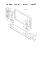
- FIG. 5 is an exploded perspective view showing the basic components of a typical side of the furniture.
- FIG. 6 is a schematic broken view on a reduced scale showing a preferred construction of the top and its manner of engagement with the posts.
- a typical knockdown furniture 10 in this case a planter, constructed in accordance with the invention is shown as comprising a plurality of planar side panels 12a, 12b, 12c and 12d, at least some of which when the furniture is assembled being angularly related to define a closed frame, as best seen in FIG. 3, of predetermined shape having corners, some of which may be right angled, as at 14 and 6, obtuse as at 18 or acute as at 20.
- each panel Located at each end of each panel on the inner side thereof is a separate identical vertical post 22 and each post and each panel have complementary interengaging releasable fastening means which may be downturned tongues or hooks 24 on the side edges of the panels which engaged with slot means 26 on the side faces of the posts as best seen in FIG. 5.
- FIG. 3 it can be seen that the sides of the obtusely angled pilaster 28c has the same degree of angularity as exists between the panels 12c and 12d.
- Complementary interengaging releasable fastening means such as the downwardly extending tongues 34 and slots 36 are provided respectively on each side of each pilaster and on each post for releasably connecting together the two posts 22a and 22b (FIG. 4) at the respective adjacent ends of a pair of panels such as 12a and 12b.
- each post has top and bottom ends 22a and 22b and, as can be seen in FIG. 2, each post has an upstanding end part 37 which extends freely above the pilasters and panels to position the top end 22a of each individual post 22 a predetermined distance above the pilasters and panels.
- a unitary cover member 38 having in horizontal cross section a shape complementary to the predetermined shape of the closed frame defined by the panels, posts and pilasters, includes a horizontal edge part 40 and a downturned flange 42 which is turned inwardly then upwardly and inwardly again in a reverse Z-shape as schematically shown in FIG. 6 to define a downwardly open channel 45 which closely embraces the upper ends 37 of the posts 22 and, as can be seen in FIG.
- the particular cover 38 illustrated is relatively deeply recessed at 46 to provide a receptical for plants.
- the upper surface of the cover could be flat or shallowly recessed to receive a seat cushion or to serve as a display surface for merchandise.
- FIGS. 1 through 3 The configuration of the frame as illustrated in FIGS. 1 through 3 is representative of the wide range of shapes permitted by the invention and where two panels converge to form an acute angle such as the angle 20 in FIG. 3, a single pilaster could be employed to join the adjacent posts together similar to the pilasters 28a, 28b, 28c. However, it is more esthetically pleasing as well as stronger to provide at acute angles of the frame a third post 22c as shown in FIG. 3 between the two end posts 22d and 22e, a first pilaster 47 joining one of the posts 22e at the end of panel 12a to the third post 22c and a second pilaster 48 joining the post 22d at the adjacent end of panel 12d to the third post 22c.
- the one pilaster 47 can be right angular similar to the pilasters 28c and 28b whereas the pilaster 48 can be similar to the obtuse angled pilaster 28a.
- the lengths of the panels defining the frame are preselected so that any desired frame shape will form angles corresponding to prefabricated pilasters, though it is, of course, within the purview of the invention to provide pilasters of any angularity to suit the user's tastes.
- the posts are preferably square in cross section with each post having a front face 49 and side faces 50, 52.
- the panels and pilasters have inturned side edges, as generally indicated at 54 and 56, respectively, in FIG. 4, adapted to abut the front faces 49 of the posts, the fastening tongues 24 and 34 being carried on the edges whereby the front faces of the pilasters and panels are spaced outwardly away from the front faces of the posts by the depth of the inturned side edges.
- the end pilasters extend the full height of the structure, and the panels may also extend the full height, or standard sized smaller panels may be stacked to define the sides of a relatively tall structure such as a room divider.
- the panels and pilasters may stop short of the floor with the posts having lower parts 57 (FIG.
- the side edges 54, 56 of the panels and pilasters are Z-shaped in horizontal cross section, the first legs 60, 62 thereof extending inwardly normal to the planes of the panel and pilaster faces, respectively, the central legs 64, 66 extending inwardly normal to the first legs parallel to and behind the panel and pilaster faces and the third legs defining the aforesaid downwardly extending tongues 24 and 34, respectively, for engagement with the slot means 26 and 36 on the side faces 50, 52 of each post.
- the respective central legs 64, 66 abut the front face 48 of each post, as seen in FIG. 4, with each center leg having a width such that the front faces of the posts are partly exposed between the first legs 60, 62 of the respective panel and pilaster side edges 54, 56 when the projections or tongues 24 and 34 are engaged with the slots 26, 36, respectively.
- the flat plates 58 may be provided with inwardly extending flanges 78 whose inner edge 80 may be bent upwardly to define a supporting track for the reception of the lower ends 57 of the posts.
- Corner brackets 82 are provided for abutting engagement with the faces of the plates 58 at the corners, fastening elements such as the screws 84 shown being provided for connecting the corner brackets 82 to the plates 58, the fastening elements also engaging the lower end of the posts.
- a straight side of an article of furniture may consist of two or more aligned panels joined together at their adjacent ends by a single common post, or the adjacent ends of the panels can each be joined to a separate post, and a generally planar pilaster can join the two posts together.
- the invention provides a wide range of uses of the component parts of panels, posts, pilasters and tops or covers to obtain different articles of furniture or different articles joined together to form a composite article as for example a planter between two seats, or a planter at one end of two seats or a room divider of any size and configuration.
- the side panels shown and described would normally be metal, e.g. stainless steel, the panels may for example comprise frames having fabric centers for use as a part or all of a wall of a room divider. Instead of stacked side panels forming the wall of a tall structure such as a room divider, cabinet drawers, shelves or lockers can be substituted.
Abstract
Description
Claims (6)
Priority Applications (1)
| Application Number | Priority Date | Filing Date | Title |
|---|---|---|---|
| US07/109,398 US4901473A (en) | 1987-10-19 | 1987-10-19 | Knockdown furniture |
Applications Claiming Priority (1)
| Application Number | Priority Date | Filing Date | Title |
|---|---|---|---|
| US07/109,398 US4901473A (en) | 1987-10-19 | 1987-10-19 | Knockdown furniture |
Publications (1)
| Publication Number | Publication Date |
|---|---|
| US4901473A true US4901473A (en) | 1990-02-20 |
Family
ID=22327450
Family Applications (1)
| Application Number | Title | Priority Date | Filing Date |
|---|---|---|---|
| US07/109,398 Expired - Fee Related US4901473A (en) | 1987-10-19 | 1987-10-19 | Knockdown furniture |
Country Status (1)
| Country | Link |
|---|---|
| US (1) | US4901473A (en) |
Cited By (12)
| Publication number | Priority date | Publication date | Assignee | Title |
|---|---|---|---|---|
| DE4334781A1 (en) * | 1993-10-13 | 1995-04-20 | Garpa Holert Handelsgesellscha | Plant tub constructed using prefabricated elements |
| US5953858A (en) * | 1997-08-22 | 1999-09-21 | Amaroo Enterprises, Inc. | Collapsible plastic planter box |
| US20050193624A1 (en) * | 2004-03-04 | 2005-09-08 | Singer Lisa R. | Garden bed assembly and method and kit therefor |
| US20050217175A1 (en) * | 2004-04-02 | 2005-10-06 | Modular Watergardens, Llc | Modular water garden construction |
| US20070101646A1 (en) * | 2005-11-07 | 2007-05-10 | Licht Jeff L | Modular planter system |
| US20080092442A1 (en) * | 2004-03-04 | 2008-04-24 | Modular Merchants, Inc., Dba Gardens To Grow A California Corporation | Garden bed assembly and method and kit therefor |
| US20100077660A1 (en) * | 2008-09-26 | 2010-04-01 | Laura Messano | Suspended planting platform for a plant container |
| US20120090256A1 (en) * | 2010-10-14 | 2012-04-19 | Andrews Robin D | Three dimensional tiled deck accessories |
| US20150201563A1 (en) * | 2014-01-17 | 2015-07-23 | Yi-Cheng Chiang | Planting box device |
| US9510518B2 (en) | 2012-07-11 | 2016-12-06 | Dimitri Shein | Sheet metal structure |
| US20220104638A1 (en) * | 2020-10-07 | 2022-04-07 | Christopher B. Peng | Modular flower bed systems |
| US11464174B1 (en) | 2021-11-30 | 2022-10-11 | Nick Suteerawanit | Disassemblable planter box |
Citations (19)
| Publication number | Priority date | Publication date | Assignee | Title |
|---|---|---|---|---|
| US151142A (en) * | 1874-05-19 | Xjixikft a ajijivh | ||
| US1109765A (en) * | 1913-09-06 | 1914-09-08 | Loose Wiles Biscuit Co | Display-stand. |
| AT73273B (en) * | 1914-03-10 | 1917-03-26 | Jan Pavlecka | Plant pot. |
| US1770722A (en) * | 1929-11-05 | 1930-07-15 | Wright Max | Table |
| US1808082A (en) * | 1928-12-26 | 1931-06-02 | Carl A Thompson | Scaffold |
| US1959800A (en) * | 1933-04-07 | 1934-05-22 | Angelo Lizzola | Flower box |
| US2480183A (en) * | 1945-01-06 | 1949-08-30 | Clarence L Dewey | Article of furniture |
| US3004814A (en) * | 1961-01-09 | 1961-10-17 | American Fixture Inc | Knockdown display tables |
| US3047183A (en) * | 1959-09-03 | 1962-07-31 | Papa Rene | Container constituting a dismantlable flower pot |
| US3331524A (en) * | 1964-07-06 | 1967-07-18 | Rudkin Wiley Corp | Window box for potted plants |
| US3759598A (en) * | 1972-06-20 | 1973-09-18 | B Limberger | Supporting frame |
| US3800470A (en) * | 1972-08-14 | 1974-04-02 | E Kleine | Window box planter |
| FR2289110A1 (en) * | 1974-10-31 | 1976-05-28 | Faysse Jean Jacques | Prefabricated window box container - has end, intermediate and corner units with connectors |
| US4009546A (en) * | 1975-10-01 | 1977-03-01 | D G Shelter Products Company | Pre-assembled unitary bay window construction |
| DE2931352A1 (en) * | 1979-08-02 | 1981-02-05 | Gerard Burgin | FURNITURE OR PART OF SUCH |
| GB2113533A (en) * | 1982-01-08 | 1983-08-10 | Ernst Koller | A frame assembly of profiled bars |
| DE3429336A1 (en) * | 1984-06-19 | 1986-02-20 | Dornheim Einrichtungen GmbH, 8591 Neusorg | Sales or presentation shelf unit |
| US4607576A (en) * | 1984-11-13 | 1986-08-26 | Stan Kranjec | Panel mounting arrangement |
| US4640045A (en) * | 1985-02-25 | 1987-02-03 | Nesbitt Richard L | Flower saddle for tombstones |
-
1987
- 1987-10-19 US US07/109,398 patent/US4901473A/en not_active Expired - Fee Related
Patent Citations (19)
| Publication number | Priority date | Publication date | Assignee | Title |
|---|---|---|---|---|
| US151142A (en) * | 1874-05-19 | Xjixikft a ajijivh | ||
| US1109765A (en) * | 1913-09-06 | 1914-09-08 | Loose Wiles Biscuit Co | Display-stand. |
| AT73273B (en) * | 1914-03-10 | 1917-03-26 | Jan Pavlecka | Plant pot. |
| US1808082A (en) * | 1928-12-26 | 1931-06-02 | Carl A Thompson | Scaffold |
| US1770722A (en) * | 1929-11-05 | 1930-07-15 | Wright Max | Table |
| US1959800A (en) * | 1933-04-07 | 1934-05-22 | Angelo Lizzola | Flower box |
| US2480183A (en) * | 1945-01-06 | 1949-08-30 | Clarence L Dewey | Article of furniture |
| US3047183A (en) * | 1959-09-03 | 1962-07-31 | Papa Rene | Container constituting a dismantlable flower pot |
| US3004814A (en) * | 1961-01-09 | 1961-10-17 | American Fixture Inc | Knockdown display tables |
| US3331524A (en) * | 1964-07-06 | 1967-07-18 | Rudkin Wiley Corp | Window box for potted plants |
| US3759598A (en) * | 1972-06-20 | 1973-09-18 | B Limberger | Supporting frame |
| US3800470A (en) * | 1972-08-14 | 1974-04-02 | E Kleine | Window box planter |
| FR2289110A1 (en) * | 1974-10-31 | 1976-05-28 | Faysse Jean Jacques | Prefabricated window box container - has end, intermediate and corner units with connectors |
| US4009546A (en) * | 1975-10-01 | 1977-03-01 | D G Shelter Products Company | Pre-assembled unitary bay window construction |
| DE2931352A1 (en) * | 1979-08-02 | 1981-02-05 | Gerard Burgin | FURNITURE OR PART OF SUCH |
| GB2113533A (en) * | 1982-01-08 | 1983-08-10 | Ernst Koller | A frame assembly of profiled bars |
| DE3429336A1 (en) * | 1984-06-19 | 1986-02-20 | Dornheim Einrichtungen GmbH, 8591 Neusorg | Sales or presentation shelf unit |
| US4607576A (en) * | 1984-11-13 | 1986-08-26 | Stan Kranjec | Panel mounting arrangement |
| US4640045A (en) * | 1985-02-25 | 1987-02-03 | Nesbitt Richard L | Flower saddle for tombstones |
Cited By (19)
| Publication number | Priority date | Publication date | Assignee | Title |
|---|---|---|---|---|
| DE4334781A1 (en) * | 1993-10-13 | 1995-04-20 | Garpa Holert Handelsgesellscha | Plant tub constructed using prefabricated elements |
| US5953858A (en) * | 1997-08-22 | 1999-09-21 | Amaroo Enterprises, Inc. | Collapsible plastic planter box |
| US20090152420A1 (en) * | 2004-03-04 | 2009-06-18 | Modular Merchants, Inc. Dba Gardens To Gro | Garden bed assembly and method and kit therefor |
| US20050193624A1 (en) * | 2004-03-04 | 2005-09-08 | Singer Lisa R. | Garden bed assembly and method and kit therefor |
| US20080092442A1 (en) * | 2004-03-04 | 2008-04-24 | Modular Merchants, Inc., Dba Gardens To Grow A California Corporation | Garden bed assembly and method and kit therefor |
| US7424787B2 (en) * | 2004-03-04 | 2008-09-16 | Modular Merchants, Inc. | Garden bed assembly and method and kit therefor |
| US20080313959A1 (en) * | 2004-03-04 | 2008-12-25 | Singer Lisa R | Garden bed assembly and method and kit therefor |
| US7490435B2 (en) | 2004-03-04 | 2009-02-17 | Modular Merchants, Inc. | Garden bed assembly and method and kit therefor |
| US7533488B2 (en) | 2004-03-04 | 2009-05-19 | Modular Merchants, Inc. | Garden bed assembly and method and kit therefor |
| US20050217175A1 (en) * | 2004-04-02 | 2005-10-06 | Modular Watergardens, Llc | Modular water garden construction |
| US20070101646A1 (en) * | 2005-11-07 | 2007-05-10 | Licht Jeff L | Modular planter system |
| US20100077660A1 (en) * | 2008-09-26 | 2010-04-01 | Laura Messano | Suspended planting platform for a plant container |
| US20120090256A1 (en) * | 2010-10-14 | 2012-04-19 | Andrews Robin D | Three dimensional tiled deck accessories |
| US9510518B2 (en) | 2012-07-11 | 2016-12-06 | Dimitri Shein | Sheet metal structure |
| US20150201563A1 (en) * | 2014-01-17 | 2015-07-23 | Yi-Cheng Chiang | Planting box device |
| US9572306B2 (en) * | 2014-01-17 | 2017-02-21 | Yi-Cheng Chiang | Planting box device |
| US20220104638A1 (en) * | 2020-10-07 | 2022-04-07 | Christopher B. Peng | Modular flower bed systems |
| US11751703B2 (en) * | 2020-10-07 | 2023-09-12 | Christopher B. Peng | Modular flower bed systems |
| US11464174B1 (en) | 2021-11-30 | 2022-10-11 | Nick Suteerawanit | Disassemblable planter box |
Similar Documents
| Publication | Publication Date | Title |
|---|---|---|
| US5595127A (en) | Shelving system | |
| US6152553A (en) | Modular furniture construction system | |
| US4901473A (en) | Knockdown furniture | |
| JP3525943B2 (en) | Cabinet assembly | |
| US3101817A (en) | Wall panel structure | |
| US4716692A (en) | Locking system for interconnecting panels | |
| US4536044A (en) | Work stations of knock-down modular components | |
| US4563040A (en) | Furniture assembly | |
| US5291700A (en) | Activities module | |
| US6681705B2 (en) | Support structure and method of assembly thereof | |
| US4324076A (en) | Wall units | |
| CA1291201C (en) | Modular furniture | |
| US4053192A (en) | Modular furniture | |
| US3844230A (en) | Displayer for paperback books | |
| US4714027A (en) | Knockdown furniture | |
| US4433880A (en) | Free standing modular unit for storing, displaying, and selling merchandise | |
| US4326760A (en) | Work stations of knock-down modular components | |
| US4699067A (en) | Knock-down display table | |
| US5826955A (en) | Modular cabinetry | |
| EP0245978B1 (en) | Cabinet | |
| US4206956A (en) | Knock-down cupboard assembly | |
| US4318576A (en) | Cabinet assembly | |
| US4976360A (en) | Merchandise display stand | |
| US4880284A (en) | Chest of drawers and method of assembly | |
| US4066370A (en) | Assembling piece |
Legal Events
| Date | Code | Title | Description |
|---|---|---|---|
| AS | Assignment |
Owner name: TAMCOR MANUFACTURING CORP., POST OFFICE BOX 695, T Free format text: ASSIGNMENT OF ASSIGNORS INTEREST.;ASSIGNOR:TAULE, JOAQUIN;REEL/FRAME:004796/0389 Effective date: 19871106 Owner name: TAMCOR MANUFACTURING CORP., POST OFFICE BOX 695, T Free format text: ASSIGNMENT OF ASSIGNORS INTEREST;ASSIGNOR:TAULE, JOAQUIN;REEL/FRAME:004796/0389 Effective date: 19871106 |
|
| FEPP | Fee payment procedure |
Free format text: PAYOR NUMBER ASSIGNED (ORIGINAL EVENT CODE: ASPN); ENTITY STATUS OF PATENT OWNER: SMALL ENTITY |
|
| FEPP | Fee payment procedure |
Free format text: PAYOR NUMBER ASSIGNED (ORIGINAL EVENT CODE: ASPN); ENTITY STATUS OF PATENT OWNER: SMALL ENTITY Free format text: PAYER NUMBER DE-ASSIGNED (ORIGINAL EVENT CODE: RMPN); ENTITY STATUS OF PATENT OWNER: SMALL ENTITY |
|
| FPAY | Fee payment |
Year of fee payment: 4 |
|
| REMI | Maintenance fee reminder mailed | ||
| LAPS | Lapse for failure to pay maintenance fees | ||
| FP | Lapsed due to failure to pay maintenance fee |
Effective date: 19980225 |
|
| STCH | Information on status: patent discontinuation |
Free format text: PATENT EXPIRED DUE TO NONPAYMENT OF MAINTENANCE FEES UNDER 37 CFR 1.362 |