US4901433A - Device for inserting a plurality of phase insulators in the cavities of the stator of a dynamo-electric machine - Google Patents
Device for inserting a plurality of phase insulators in the cavities of the stator of a dynamo-electric machine Download PDFInfo
- Publication number
- US4901433A US4901433A US07/211,012 US21101288A US4901433A US 4901433 A US4901433 A US 4901433A US 21101288 A US21101288 A US 21101288A US 4901433 A US4901433 A US 4901433A
- Authority
- US
- United States
- Prior art keywords
- guide blades
- stator
- cavities
- phase
- phase insulators
- Prior art date
- Legal status (The legal status is an assumption and is not a legal conclusion. Google has not performed a legal analysis and makes no representation as to the accuracy of the status listed.)
- Expired - Lifetime
Links
- 239000012212 insulator Substances 0.000 title claims abstract description 75
- 238000003780 insertion Methods 0.000 claims abstract description 30
- 230000037431 insertion Effects 0.000 claims abstract description 30
- 210000001331 nose Anatomy 0.000 claims description 2
- 238000004804 winding Methods 0.000 description 17
- 238000000034 method Methods 0.000 description 4
- 238000007796 conventional method Methods 0.000 description 1
- 238000003475 lamination Methods 0.000 description 1
- 238000004519 manufacturing process Methods 0.000 description 1
- 239000000463 material Substances 0.000 description 1
- 239000004033 plastic Substances 0.000 description 1
- 229920003023 plastic Polymers 0.000 description 1
- 230000000284 resting effect Effects 0.000 description 1
- 125000006850 spacer group Chemical group 0.000 description 1
- 230000003068 static effect Effects 0.000 description 1
Images
Classifications
-
- H—ELECTRICITY
- H02—GENERATION; CONVERSION OR DISTRIBUTION OF ELECTRIC POWER
- H02K—DYNAMO-ELECTRIC MACHINES
- H02K15/00—Processes or apparatus specially adapted for manufacturing, assembling, maintaining or repairing of dynamo-electric machines
- H02K15/10—Applying solid insulation to windings, stators or rotors, e.g. applying insulating tapes
-
- Y—GENERAL TAGGING OF NEW TECHNOLOGICAL DEVELOPMENTS; GENERAL TAGGING OF CROSS-SECTIONAL TECHNOLOGIES SPANNING OVER SEVERAL SECTIONS OF THE IPC; TECHNICAL SUBJECTS COVERED BY FORMER USPC CROSS-REFERENCE ART COLLECTIONS [XRACs] AND DIGESTS
- Y10—TECHNICAL SUBJECTS COVERED BY FORMER USPC
- Y10T—TECHNICAL SUBJECTS COVERED BY FORMER US CLASSIFICATION
- Y10T29/00—Metal working
- Y10T29/49—Method of mechanical manufacture
- Y10T29/49002—Electrical device making
- Y10T29/49009—Dynamoelectric machine
-
- Y—GENERAL TAGGING OF NEW TECHNOLOGICAL DEVELOPMENTS; GENERAL TAGGING OF CROSS-SECTIONAL TECHNOLOGIES SPANNING OVER SEVERAL SECTIONS OF THE IPC; TECHNICAL SUBJECTS COVERED BY FORMER USPC CROSS-REFERENCE ART COLLECTIONS [XRACs] AND DIGESTS
- Y10—TECHNICAL SUBJECTS COVERED BY FORMER USPC
- Y10T—TECHNICAL SUBJECTS COVERED BY FORMER US CLASSIFICATION
- Y10T29/00—Metal working
- Y10T29/53—Means to assemble or disassemble
- Y10T29/5313—Means to assemble electrical device
- Y10T29/53143—Motor or generator
- Y10T29/53152—Means to position insulation
-
- Y—GENERAL TAGGING OF NEW TECHNOLOGICAL DEVELOPMENTS; GENERAL TAGGING OF CROSS-SECTIONAL TECHNOLOGIES SPANNING OVER SEVERAL SECTIONS OF THE IPC; TECHNICAL SUBJECTS COVERED BY FORMER USPC CROSS-REFERENCE ART COLLECTIONS [XRACs] AND DIGESTS
- Y10—TECHNICAL SUBJECTS COVERED BY FORMER USPC
- Y10T—TECHNICAL SUBJECTS COVERED BY FORMER US CLASSIFICATION
- Y10T29/00—Metal working
- Y10T29/53—Means to assemble or disassemble
- Y10T29/5313—Means to assemble electrical device
- Y10T29/53143—Motor or generator
- Y10T29/53161—Motor or generator including deforming means
Definitions
- the present invention relates to a method and to a device for the insertion of a plurality of phase insulators in the cavities of a stator of a dynamo-electric machine.
- phase insulators indicates the insulating elements which are used to separate various windings which are engaged in the same cavities of the stator of a dynamo-electric machine.
- FIG. 1 of the appended drawings One example of a phase insulator normally used in the art is illustrated in perspective in FIG. 1 of the appended drawings.
- the insulator is constituted by a sheet of insulating plastics material generally indicated 1 and comprising two end portions 2 and a plurality of bridges 3 which interconnect them and define windows la.
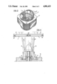
- FIG. 2 of the appended drawings illustrates in perspective a stator 4 of a dynamo-electric machine provided with a plurality of phase insulators 1 of the type illustrated in FIG. 1.
- the stator 4 has, in conventional manner, a structure constituted by a pack of laminations having a cylindrical central through aperture 5. A plurality of cavities 6 which are angularly spaced from each other open in the wall of the central aperture 5.
- Reference numeral 7 generally indicates a primary winding whose turns are inserted in some of the cavities 6 of the stator.
- a secondary winding (not illustrated) is inserted in the same cavities after the arrangement of phase insulators 1 in the latter.
- the bridges 3 of each phase insulator 1 are inserted each in a corresponding cavity of the stator to separate the primary winding from the secondary winding, while the end portions 2 of each phase insulator 1 project from the ends of the stator and serve to insulate the corresponding parts of the windings.
- a device for inserting a plurality of phase insulators in the cavities of the stator of a dynamo-electric machine which comprises:
- a plurality of guide blades for inserting the phase insulators disposed circumferentially around a central axis
- an insertion member which is slidable between the series of guide blades, having a circumferential series of axial grooves in its outer surface in which the various guide blades are engaged, this member being movable from a rest position, in which it allows a plurality of phase insulators to be pre-arranged on the guide blades, to an operative position to cause the phase insulators to slide over the guide blades and the subsequent insertion of these phase insulators within the cavities of a stator arranged at the end of the circumferential series of guide blades.
- the object of the present invention is to provide a new method and corresponding device for the insertion of the phase insulators in the cavities of the stator which allows the phase insulators to be pre-arranged on the guide blades particularly simply, easily and reliably so as to allow this operation to be carried out even by automatic equipment if so desired.
- this invention provides a device of the type indicated above, characterized in that at least some of the guide blades are movable from their normal operative positions to positions spaced radially outwardly in which it is easy to position the phase insulators above them.
- the guide blades are articulated to a support structure at their ends opposite those on which the stator is placed, about an axis perpendicular to the axis of the circumferential series of guide blades so that each of these guide blades can pivot about its articulation axis between its operative position and its open position diverging outwardly.
- the present invention also has as its subject a method which provides for the use of the device mentioned above, including the stage of pre-arranging the guide blades in their positions spaced radially outwardly relative to their normal operative positions, the stage of positioning a plurality of phase insulators on the guide blades so pre-arranged, he stage of returning the guide blades to their normal operative positions, and finally the stage of driving the movement of the insertion member to its operative position so as to cause the phase insulators to slide on the guide blades and their subsequent insertion in the cavities of a stator arranged in correspondence with the free ends of the circumferential series of guide blades.
- the present invention allows the phase insulators to be positioned above the guide blades even with automatic equipment.
- the spaces defined between the adjacent blades are sufficiently wide to ensure that the phase insulators can be positioned without any danger of their deformation.
- the insertion of the phase insulators is preferably carried out with a device dedicated solely to this operation, which is not used for the insertion of the prewound coils of a winding in the cavities of the stator at the same time as the phase insulators.
- automatic equipment which includes several machines in which the various successive stages of the manufacture are carried out, in particular, a first for the insertion of a first winding in the cavities of the stator, a second machine for the insertion of the phase insulators and a third machine for the insertion of a second winding in the cavities of the stator, the loading of the phase insulators onto the guide blades of the second being carried out by automatic equipment.
- FIG. 1 is a perspective view of a phase insulator
- FIG. 2 is a perspective view of a stator of a dynamo-electric machine, with a winding and the phase insulators already inserted in the cavities,
- FIG. 3 is a schematic sectional view of a device according to the present invention in a first operative condition
- FIG. 4 is a cross-section of the device of the invention in a second operative position
- FIG. 5 is a schematic plan view taken on the arrow V of FIG. 4.
- FIG. 6 is a cross-section taken on the line VI--VI of FIG. 1.
- FIGS. 1 and 2 of the appended drawings have already been described above.
- FIGS. 3 to 5 illustrate one embodiment of a device according to the invention.
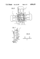
- the device for inserting the phase insulators comprises a plurality of fingers or guide blades 8 disposed circumferentially around a central axis 9 and extending parallel to this axis in their normal operative positions illustrated in FIG. 3.
- the blades 8 are arranged circumferentially so as to leave longitudinal spaces between them.
- the various blades 8 have different sectional dimensions and profiles for reasons which will be clarified below.
- a substantially conical insertion member 10 is slidable within the circumferential series of guide blades 8 and has a circumferential series of axial grooves 11 in its outer surface which are slidably engaged by the various guide blades 8.
- the insertion member 10 is fixed by a screw 12 and a key 13a to a movable shaft 13 intended to be driven by actuator means of any known type (not illustrated) to cause the axial movement of the insertion member 10.
- a stator 4 of the type illustrated in FIG. 2 having a laminated body with a central aperture 5 of circular section into which open a plurality of axial cavities 6.
- the coils 7 of a primary winding are already inserted in the cavities of the stator 6.
- the device illustrated is used to introduce a plurality of phase insulators 1 of the type illustrated in FIG. 1 into the cavities 6 before the stator is passed to another station where a subsequent winding is to be inserted.
- the circumferential series of guide blades 8 is conformed in such a manner that the stator 4 may be fitted onto it and rests on it in such a manner that the longitudinal spaces between adjacent blades face corresponding cavities of the stator.
- stator 4 rests on shoulders 14 on the outer surfaces of the guide blades 8.
- the thrust member 10 is predisposed in a lowered rest position (illustrated in continuous outline in FIG. 3) so as to enable the insulators 1 to be fitted over the blades 8, resting on the upper conical surface of the thrust member 10.
- Each insulator is fitted onto the guide blades in such a manner that each of the blades concerned engages a corresponding window 1a in the phase insulator.
- the thrust member 10 is moved to its operative position (illustrated in broken outline in FIG. 3) so as to cause the phase insulators 1 to slide over the guide blades 8 and to be inserted subsequently in the cavities 6 of the stator.
- the known art provides for the manual arrangement of the phase insulators 1 above the guide blades 8.
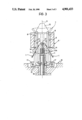
- the guide blades 8 are fixed rigidly in their normal operative positions (illustrated in broken outline in FIG. 5). It is clear from FIG. 5 that, in this condition, the insertion of the bridges 3 of each phase insulator 1 in a corresponding space between two adjacent blades 8 causes deformation of the insulator.
- the guide blades or at least some of these may be displaced from their normal operative positions (illustrated in broken outline in FIG. 5) to positions spaced radially outwardly (illustrated in continuous outline in FIG. 5) so as to facilitate the positioning of the phase insulators 1.
- FIG. 5 illustrates in plan four phase insulators intended to be fitted onto the circumferential series of guide blades. As seen, when the blades are in their most open positions, spaced radially outwardly from their normal operative positions, the phase insulators may be positioned without interference with the blades and consequent deformation of the phase insulators.
- FIG. 5 illustrates in plan four phase insulators intended to be fitted onto the circumferential series of guide blades. As seen, when the blades are in their most open positions, spaced radially outwardly from their normal operative positions, the phase insulators may be positioned without interference with the blades and consequent deformation of the phase insulators.
- FIG. 5 also shows how the spacing of the open positions of the guide blades relative to the normal operative positions should preferably vary for the various guide blades in order to avoid interference with the insulators during positioning of the latter.
- the blades indicated 8a in the embodiment illustrated in FIG. 5 must be spaced further outwardly from their normal operative positions in that otherwise these would interfere with the zone in which two adjacent insulators are to be superposed.
- a further preferred characteristic of the invention lies in the fact that the insertion device described is used solely for the insertion of the phase insulators and not for the insulators together with the coils of a winding.
- the device illustrated is thus preferably dedicated solely to the operation of introducing the phase insulators into the cavities of the stator.
- the sections of the various guide blades preferably differ in dependence on their use.
- the blades indicated 8b and 8c in FIG. 5 have sections corresponding to the width of the respective windows la which are engaged thereby.
- the movement of the guide blades 8 from their normal operative positions to their open positions spaced radially outwardly may be achieved in any manner.
- each blade may be pivoted about the axis 17 between the operative position illustrated in broken outline in FIG. 4 and an open position, diverging outwardly, illustrated in continuous outline in FIG. 4.
- the pivoting of the blades 8 may for example be controlled by a sleeve 18 slidable coaxially on the exterior of the shaft 13 and having a circumferential groove 19 which is engaged by projecting noses 20 of the levers 15.
- the loading of the phase insulators 1 onto the guide blades 8 may be effected by automatic equipment after the guide blades have been moved into their open positions.
- the phase insulators 1 may be positioned by take-up members 21 provided with suction pads 22 (FIG. 4). Once the take-up members 21 have positioned the phase insulators 1 above the guide blades, these latter may be returned to their normal operative positions, after which the stator 4 is fitted and the insertion member 10 is brought into its operative position so as to cause the insertion of the insulators into the cavities of the stator.
- Automatic equipment for inserting the windings and the phase insulators into the cavities of the stator, comprising a first machine including a device for inserting a first winding, a second machine in which the insertion of the phase insulators by means of the device according to the invention is carrie out completely automatically, and a third machine in which a further winding is inserted into the cavities of the stator.
- the bridges 3 of each phase insulator sometimes have a line of longitudinal folding to facilitate their insertion in the corresponding spaces between the guide blades.
- these folds are no longer necessary since the positioning of the phase insulators may be carried out easily after the guide blades have been arranged in their open positions.
- the blades 8 may have--in known manner--longitudinal lips on their outer surfaces for engaging the sides of the cavities of the stator.
- the insulators may also have shapes different from that illustrated in the appended drawings.
- means--of known type-- may be provided for ensuring the correct angular positioning of the stator on the blades.
Landscapes
- Engineering & Computer Science (AREA)
- Manufacturing & Machinery (AREA)
- Power Engineering (AREA)
- Manufacture Of Motors, Generators (AREA)
- Insulation, Fastening Of Motor, Generator Windings (AREA)
- Automatic Assembly (AREA)
Abstract
Description
Claims (5)
Applications Claiming Priority (2)
| Application Number | Priority Date | Filing Date | Title |
|---|---|---|---|
| IT67178A/88 | 1988-03-04 | ||
| IT67178/88A IT1219076B (en) | 1988-03-04 | 1988-03-04 | PROCEDURE AND DEVICE FOR INSERTING A MULTIPLE OF PHASE ISOLATORS IN THE STATOR GROOVES OF A DYNAMOELECTRIC MACHINE |
Related Child Applications (1)
| Application Number | Title | Priority Date | Filing Date |
|---|---|---|---|
| US07/454,588 Division US4970774A (en) | 1988-03-04 | 1989-12-21 | Method for inserting a plurality of phase insulators in the cavities of the stator of a dynamo-electric machine |
Publications (1)
| Publication Number | Publication Date |
|---|---|
| US4901433A true US4901433A (en) | 1990-02-20 |
Family
ID=11300246
Family Applications (2)
| Application Number | Title | Priority Date | Filing Date |
|---|---|---|---|
| US07/211,012 Expired - Lifetime US4901433A (en) | 1988-03-04 | 1988-06-24 | Device for inserting a plurality of phase insulators in the cavities of the stator of a dynamo-electric machine |
| US07/454,588 Expired - Lifetime US4970774A (en) | 1988-03-04 | 1989-12-21 | Method for inserting a plurality of phase insulators in the cavities of the stator of a dynamo-electric machine |
Family Applications After (1)
| Application Number | Title | Priority Date | Filing Date |
|---|---|---|---|
| US07/454,588 Expired - Lifetime US4970774A (en) | 1988-03-04 | 1989-12-21 | Method for inserting a plurality of phase insulators in the cavities of the stator of a dynamo-electric machine |
Country Status (6)
| Country | Link |
|---|---|
| US (2) | US4901433A (en) |
| EP (1) | EP0331651B1 (en) |
| JP (1) | JPH01228740A (en) |
| DE (1) | DE68903853T2 (en) |
| ES (1) | ES2037467T3 (en) |
| IT (1) | IT1219076B (en) |
Cited By (11)
| Publication number | Priority date | Publication date | Assignee | Title |
|---|---|---|---|---|
| US5553372A (en) * | 1992-03-09 | 1996-09-10 | Odawara Engineering Kk | Apparatus for inserting insulation sheets into slots of a stator core |
| US6141865A (en) * | 1997-09-04 | 2000-11-07 | Honda Giken Kogyo Kabushiki Kaisha | Winding method and winding apparatus for producing stators for electric motors |
| US6389678B1 (en) * | 1996-05-31 | 2002-05-21 | Emerson Electric Co. | Method of constructing a salient pole motor |
| US20150207391A1 (en) * | 2012-07-12 | 2015-07-23 | Honda Motor Co., Ltd. | Electrical conductor aligning device and aligning method |
| US20170302143A1 (en) * | 2013-10-18 | 2017-10-19 | Atop S.P.A. | Apparatus and method for manufacturing components of dynamoelectric machines |
| US10224789B2 (en) | 2011-03-07 | 2019-03-05 | Atop S.P.A. | Apparatus for aligning conductors of coil members in cores of electric dynamo machines |
| US10411570B2 (en) | 2011-05-16 | 2019-09-10 | Atop S.P.A. | Apparatus for manufacturing coil members for cores of dynamo electric machines by bending |
| US10749418B2 (en) | 2015-04-30 | 2020-08-18 | Atop S.P.A. | Methods for forming woven undulated coil assemblies |
| US11108308B2 (en) * | 2015-12-15 | 2021-08-31 | Grob-Werke Gmbh & Co. Kg | Apparatus for installing a wire package into an electrical machine |
| CN115008190A (en) * | 2022-07-21 | 2022-09-06 | 重庆水轮机厂有限责任公司 | Assembly process of water distributor of through-flow turbine |
| US11557946B2 (en) | 2015-07-20 | 2023-01-17 | Atop S.P.A. | Method for inserting undulated coil assemblies in slots of cores of dynamoelectric machines |
Families Citing this family (3)
| Publication number | Priority date | Publication date | Assignee | Title |
|---|---|---|---|---|
| US5454156A (en) * | 1994-04-18 | 1995-10-03 | Morr; Charles W. | Apparatus and method for inserting stator coils |
| US5829118A (en) * | 1996-03-11 | 1998-11-03 | Kollmorgen Corporation | Method and apparatus for slotless stator manufacturing |
| CN103084827B (en) * | 2013-01-11 | 2015-07-08 | 宁波永信汽车部件制造有限公司 | Spring press fitting device of adjusting block |
Citations (2)
| Publication number | Priority date | Publication date | Assignee | Title |
|---|---|---|---|---|
| US4276689A (en) * | 1979-04-05 | 1981-07-07 | General Electric Company | Apparatus and method for axial insertion of dynamoelectric machine end turn insulation |
| US4566180A (en) * | 1982-09-30 | 1986-01-28 | Industra Products, Inc. | Method and apparatus for placing coils and intermediate insulators in cores |
Family Cites Families (1)
| Publication number | Priority date | Publication date | Assignee | Title |
|---|---|---|---|---|
| US4831715A (en) * | 1983-03-07 | 1989-05-23 | Industra Products, Inc. | Method and apparatus for positioning intermediate insulators in cores |
-
1988
- 1988-03-04 IT IT67178/88A patent/IT1219076B/en active
- 1988-06-24 US US07/211,012 patent/US4901433A/en not_active Expired - Lifetime
- 1988-10-14 JP JP63260357A patent/JPH01228740A/en active Pending
-
1989
- 1989-02-28 EP EP89830083A patent/EP0331651B1/en not_active Expired - Lifetime
- 1989-02-28 ES ES198989830083T patent/ES2037467T3/en not_active Expired - Lifetime
- 1989-02-28 DE DE89830083T patent/DE68903853T2/en not_active Expired - Fee Related
- 1989-12-21 US US07/454,588 patent/US4970774A/en not_active Expired - Lifetime
Patent Citations (2)
| Publication number | Priority date | Publication date | Assignee | Title |
|---|---|---|---|---|
| US4276689A (en) * | 1979-04-05 | 1981-07-07 | General Electric Company | Apparatus and method for axial insertion of dynamoelectric machine end turn insulation |
| US4566180A (en) * | 1982-09-30 | 1986-01-28 | Industra Products, Inc. | Method and apparatus for placing coils and intermediate insulators in cores |
Cited By (18)
| Publication number | Priority date | Publication date | Assignee | Title |
|---|---|---|---|---|
| US5553372A (en) * | 1992-03-09 | 1996-09-10 | Odawara Engineering Kk | Apparatus for inserting insulation sheets into slots of a stator core |
| US6389678B1 (en) * | 1996-05-31 | 2002-05-21 | Emerson Electric Co. | Method of constructing a salient pole motor |
| US6141865A (en) * | 1997-09-04 | 2000-11-07 | Honda Giken Kogyo Kabushiki Kaisha | Winding method and winding apparatus for producing stators for electric motors |
| US10224789B2 (en) | 2011-03-07 | 2019-03-05 | Atop S.P.A. | Apparatus for aligning conductors of coil members in cores of electric dynamo machines |
| US10411570B2 (en) | 2011-05-16 | 2019-09-10 | Atop S.P.A. | Apparatus for manufacturing coil members for cores of dynamo electric machines by bending |
| US20150207391A1 (en) * | 2012-07-12 | 2015-07-23 | Honda Motor Co., Ltd. | Electrical conductor aligning device and aligning method |
| US9917494B2 (en) * | 2012-07-12 | 2018-03-13 | Honda Motor Co., Ltd. | Electrical conductor aligning device |
| US10523097B2 (en) | 2012-07-12 | 2019-12-31 | Honda Motor Co., Ltd. | Electrical conductor aligning method |
| US20170302143A1 (en) * | 2013-10-18 | 2017-10-19 | Atop S.P.A. | Apparatus and method for manufacturing components of dynamoelectric machines |
| US10305354B2 (en) * | 2013-10-18 | 2019-05-28 | Atop S.P.A. | Apparatus for manufacturing components of dynamoelectric machines |
| US10749418B2 (en) | 2015-04-30 | 2020-08-18 | Atop S.P.A. | Methods for forming woven undulated coil assemblies |
| US11336160B2 (en) | 2015-04-30 | 2022-05-17 | Atop S.Pa. | Methods for forming woven undulated coil assemblies |
| US11658553B2 (en) | 2015-04-30 | 2023-05-23 | Atop S.P.A. | Apparatuses for forming woven undulated coil assemblies |
| US11557946B2 (en) | 2015-07-20 | 2023-01-17 | Atop S.P.A. | Method for inserting undulated coil assemblies in slots of cores of dynamoelectric machines |
| US12470114B2 (en) | 2015-07-20 | 2025-11-11 | Atop S.P.A. | Apparatus for inserting an undulated coil assembly in slots of a core of a stator of a dynamoelectric machine |
| US11108308B2 (en) * | 2015-12-15 | 2021-08-31 | Grob-Werke Gmbh & Co. Kg | Apparatus for installing a wire package into an electrical machine |
| CN115008190A (en) * | 2022-07-21 | 2022-09-06 | 重庆水轮机厂有限责任公司 | Assembly process of water distributor of through-flow turbine |
| CN115008190B (en) * | 2022-07-21 | 2023-08-11 | 重庆水轮机厂有限责任公司 | Assembling process of tubular turbine water guide mechanism |
Also Published As
| Publication number | Publication date |
|---|---|
| JPH01228740A (en) | 1989-09-12 |
| EP0331651B1 (en) | 1992-12-16 |
| US4970774A (en) | 1990-11-20 |
| EP0331651A1 (en) | 1989-09-06 |
| IT1219076B (en) | 1990-04-24 |
| DE68903853T2 (en) | 1993-10-21 |
| IT8867178A0 (en) | 1988-03-04 |
| DE68903853D1 (en) | 1993-01-28 |
| ES2037467T3 (en) | 1993-06-16 |
Similar Documents
| Publication | Publication Date | Title |
|---|---|---|
| US4901433A (en) | Device for inserting a plurality of phase insulators in the cavities of the stator of a dynamo-electric machine | |
| EP0188601B1 (en) | Slotless and toothless wound stators and methods of production | |
| US4090290A (en) | Method of making an electric motor winding insulating barrier | |
| US5717273A (en) | Insulating armature end turn cap | |
| US4455743A (en) | Apparatus and method for placing coils and phase insulation in the slots of a dynamoelectric machine stator core member | |
| US8561447B2 (en) | Twisting device adapted to simultaneously twist a plurality of electric bar conductors for making a stator or rotor winding for an electric machine and an extractor assembly suitable for cooperating with said twisting device | |
| EP0006514B1 (en) | Method of assembly for electric motor stators | |
| CA1155272A (en) | Apparatus and method for axial insertion of dynamoelectric machine end turn insulation | |
| US4247978A (en) | Methods of making slot liners and stator assemblies including same | |
| US4351103A (en) | Method and apparatus for supporting slot liner cuffs during coil insertion | |
| US4216571A (en) | Methods and apparatus for inserting winding end turn phase insulation | |
| US6938322B2 (en) | Method of making an electric motor stator assembly having a novel winding arrangement | |
| US4831715A (en) | Method and apparatus for positioning intermediate insulators in cores | |
| US4151436A (en) | Electrical insulator for slotted magnetic cores | |
| EP0045125A1 (en) | Stators for electric motors | |
| US4160316A (en) | Apparatus for positioning insulating members in magnetic core slots | |
| GB2165170A (en) | Coil placing machine for placing prewound electrical coils in selected slots of a slotted core of a dynamo-electric machine stator | |
| US4205429A (en) | Methods and apparatus for inserting coils into dynamoelectric machine stator assemblies | |
| WO2000036732A3 (en) | Electric motor and a method for making an electric motor | |
| US4204318A (en) | Apparatus for retracting the stator coil of an electric motor | |
| EP0058351B1 (en) | Connecting device for the beginnings and ends of the coils of an induction motor rotor winding | |
| GB2081027A (en) | Insulating stators of electric motors | |
| ITTO20060336A1 (en) | APPLIANCES AND PROCEDURES FOR THE INSERTION OF REELS AND DOUBLES IN THE DRAWINGS OF DYNAMOELECTRIC MACHINES | |
| SU655035A1 (en) | Device for placing filled winding into electric machine stator slots | |
| JPH0353856B2 (en) |
Legal Events
| Date | Code | Title | Description |
|---|---|---|---|
| AS | Assignment |
Owner name: OFFICINE MECCANICHE PAVESI & C. S.P.A., AN ITALIA Free format text: ASSIGNMENT OF ASSIGNORS INTEREST.;ASSIGNOR:BARRERA, GIORGIO;REEL/FRAME:005195/0337 Effective date: 19880725 |
|
| STCF | Information on status: patent grant |
Free format text: PATENTED CASE |
|
| AS | Assignment |
Owner name: OFFICINE MECCANICHE PAVESI S.R.L. Free format text: MERGER;ASSIGNOR:OFFICINE MECCANICHE PAVESI E C. S.P.A.;REEL/FRAME:005437/0863 Effective date: 19891215 Owner name: OFFICINE MECCANICHE PAVESI & C. S.P.A. Free format text: MERGER;ASSIGNOR:MECBAR S.P.A.;REEL/FRAME:005437/0856 Effective date: 19730926 Owner name: PAVESI S.R.L. Free format text: CHANGE OF NAME;ASSIGNOR:OFFICINE MECCANICHE PAVESI S.R.L.;REEL/FRAME:005437/0873 Effective date: 19891004 |
|
| FEPP | Fee payment procedure |
Free format text: PAYOR NUMBER ASSIGNED (ORIGINAL EVENT CODE: ASPN); ENTITY STATUS OF PATENT OWNER: SMALL ENTITY |
|
| AS | Assignment |
Owner name: AXIS S.P.A., ITALY Free format text: ASSIGNMENT OF ASSIGNORS INTEREST.;ASSIGNOR:AIME, PIERO (AS TRUSTEE IN BANKRUPTCY OF PAVESI S.R.L.);REEL/FRAME:006425/0745 Effective date: 19921111 |
|
| FPAY | Fee payment |
Year of fee payment: 4 |
|
| FPAY | Fee payment |
Year of fee payment: 8 |
|
| FPAY | Fee payment |
Year of fee payment: 12 |