US4901287A - Underwater sonar array - Google Patents
Underwater sonar array Download PDFInfo
- Publication number
- US4901287A US4901287A US07/174,046 US17404688A US4901287A US 4901287 A US4901287 A US 4901287A US 17404688 A US17404688 A US 17404688A US 4901287 A US4901287 A US 4901287A
- Authority
- US
- United States
- Prior art keywords
- cable
- hydrophone
- array
- attached
- instrumentation unit
- Prior art date
- Legal status (The legal status is an assumption and is not a legal conclusion. Google has not performed a legal analysis and makes no representation as to the accuracy of the status listed.)
- Expired - Lifetime
Links
- URLKBWYHVLBVBO-UHFFFAOYSA-N Para-Xylene Chemical group CC1=CC=C(C)C=C1 URLKBWYHVLBVBO-UHFFFAOYSA-N 0.000 claims abstract description 8
- 229920002635 polyurethane Polymers 0.000 claims abstract description 5
- 239000004814 polyurethane Substances 0.000 claims abstract description 5
- 239000011347 resin Substances 0.000 claims abstract description 4
- 229920005989 resin Polymers 0.000 claims abstract description 4
- 238000013480 data collection Methods 0.000 claims description 7
- 239000000463 material Substances 0.000 claims description 3
- 238000004382 potting Methods 0.000 claims description 2
- 239000011248 coating agent Substances 0.000 claims 1
- 238000000576 coating method Methods 0.000 claims 1
- 239000004033 plastic Substances 0.000 claims 1
- 229920003023 plastic Polymers 0.000 claims 1
- 239000004020 conductor Substances 0.000 abstract description 6
- 230000000694 effects Effects 0.000 abstract description 3
- 239000002184 metal Substances 0.000 abstract 1
- 238000003491 array Methods 0.000 description 4
- 238000009413 insulation Methods 0.000 description 2
- XLYOFNOQVPJJNP-UHFFFAOYSA-N water Substances O XLYOFNOQVPJJNP-UHFFFAOYSA-N 0.000 description 2
- 230000009286 beneficial effect Effects 0.000 description 1
- 238000010276 construction Methods 0.000 description 1
- 238000012986 modification Methods 0.000 description 1
- 230000004048 modification Effects 0.000 description 1
Images


Classifications
-
- G—PHYSICS
- G01—MEASURING; TESTING
- G01V—GEOPHYSICS; GRAVITATIONAL MEASUREMENTS; DETECTING MASSES OR OBJECTS; TAGS
- G01V1/00—Seismology; Seismic or acoustic prospecting or detecting
- G01V1/16—Receiving elements for seismic signals; Arrangements or adaptations of receiving elements
- G01V1/20—Arrangements of receiving elements, e.g. geophone pattern
- G01V1/201—Constructional details of seismic cables, e.g. streamers
Definitions
- This invention relates to underwater sonar arrays and more particularly to an elongated array construction which is caused to remain essentially vertical despite being exposed to significant cross currents.
- the Applicants have devised a sonar array of substantial length in which a number of hydrophones are distributed along a cable and which has a minimum amount of deflection from the vertical if placed at a substantial depth in the ocean where the cross currents do not exceed 1-2 knots.
- the array is attached to a tethered data collection and instrumentation unit and may be suspended therefrom and held vertical by means of a weight or may be held above the data collection and instrumentation unit (hereafter "data unit”) by means of a float.
- the cable itself has been designed to present a minimum cross sectional area to the currents tending to push the array horizontally.
- the cable itself has been designed such that, as the need for conducting wires is reduced with distance from the data unit (since several hydrophones are connected close to the data unit and there is no need to extend their conductors further), the effective diameter of the cable may be reduced. Although this reduction could be done at each hydrophone, the practical choice is to divide the cable into a reasonable number of sections such as four or six and provide a smaller diameter section for each one-fourth or one-sixth of the entire cable length. This reduces the number of interconnections to a reasonable number and still has the very beneficial effect of reducing the effective area of the cable exposed to cross currents.
- FIG. 1 is a schematic drawing of the data unit, the sonar array, the tether and the anchor placed in the ocean;
- FIG. 1A is a large scale drawing of portion A of FIG. 1;
- FIG. 2 is a schematic drawing of a data unit, tether, anchor and another embodiment of the sonar array.
- FIG. 3 is a drawing of a portion of the cable with the jacket partly removed, showing the end fittings used for the strength members;
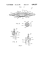
- FIG. 4 is a cross sectional view of a hydrophone unit used in the array of the present invention.
- FIG. 5 is a cross-sectional view taken through line 5--5 of FIG. 4;
- FIG. 6 is a perspective view of part of a portion of the bracket member used in the hydrophone unit of FIGS. 4 and 5;
- FIG. 7 is a perspective view of part of the bracket member of FIG. 6, seen from the opposite side;
- FIG. 8 is a schematic drawing of the array shown in association with cross sectional views of the cable used in the various sections designated Figures 8A, 8B, 8C and 8D.
- a data and instrumentation unit 10 is anchored to the ocean bottom by means of a tethering rope or cable 12, and an anchor 14.
- the tether is attached essentially at the center of an end panel 16 ofthe data unit 10.
- an acoustic array 18 including a cable 20 and a substantial number of hydrophone units 22 fastened to the cable.
- a weight 24, preferably in the form of an oblate spheroid is attached at the end of the array and tends to keep the array in a near vertical attitude.
- FIG. 1A is an enlarged view of a portion of array 18 showing the general arrangement of the hydrophone units 22 along the cable 20. It will be observed that the hydrophone units 22 are smoothly molded to the cable 20 to produce as little resistance or drag as possible, consistent with theirrequired diameter.
- FIG. 2 shows a second embodiment of our array attached to a data unit 26 which is tethered to the ocean bottom by means of a rope or cable 28 held in place with an anchor 30.
- the array 32 is attached to the data unit 26 at the top and is suspended from a float 34.
- the float 34 is preferablydesigned to present as small a surface as possible in the direction of the cross currents in order to keep the array 32 in as nearly vertical an attitude as possible.
- the conducting wires 36 and the strength member 38 which is a wire rope which may be three sixty-fourths inch (3/64") in diameter, or a comparable size depending somewhat upon the length the array used and the ballast weight employed.
- the strength member is cut and a portion removed which is slightly shorter than the length of the bracket employed in the hydrophone unit 22.
- a ball fitting 40 is swaged in place, attaching it very securely to the wire rope.
- FIG. 4 is a cross-sectional view of a hydrophone unit 22 showing two sections of the center strength member 38 with the attached ball fittings 40 engaged with opposite ends of a bracket member 42 which forms part of the hydrophone unit 22.
- the bracket 42 includes flattened end parts 46 which support a circuit board 48 containing a preamplifier and a pair of tension members 50 extending between the hook parts which form a receptacle for a cylindricalhydrophone 52.
- This entire assembly is covered with a first layer of paraxylene resin and then molded into a smooth tapered cylindrical form covering part of the cable 20 as shown with a potting 54 of polyurethane material.
- the conducting wires 36 are also included in the molded assembly.
- FIG. 5 is a cross-sectional view taken along line 5--5 of FIG. 4 and shows the bracket member 42 in end view with the flattened end part 46 supporting circuit board 48 and hook 44 which captures the ball fitting 40.
- the hydrophone 50 is shown in dotted outline with the entire assembly encased in the molded polyurethane material.
- FIGS. 6 and 7 are perspective views of opposite sides of one end of the bracket 42 shown in association with the ball fitting 40 attached to cable38.
- the open end of the hook portion 44 is facing the reader and the ball fitting member 40 is shown seated against hook portion 40.
- FIG. 7 the same structure is shown turned the opposite way with the flattened circuit board support part 46 facing the reader. It will be understood that the bracket 42 is symmetrical and that the lower half would appear as a mirror image of those shown in FIGS. 6 and 7.
- FIG. 8 is shown a diagrammatic representation of the array 18 in association with a number of cross-sections of cable 20 showing the mannerin which the cable is, or may be, reduced in cross-section with greater distances from the data unit 10.
- the array 18 contemplates a string of 32 hydrophones divided into four groups, each of which incorporates a different number of conductors. Beginning with the cable section nearest the data unit 10, the cable section shown in FIG. 8A includes the center strength member 38, a layer of insulation 56 covering member 38, thirty-five insulated conducting wires 36 and an outer jacket 58. The nextcable section outboard of the first is shown in FIG. 8B.
- this section has twenty-nine conducting wires and is significantly smaller in diameter.
- Thethird cable section shown in FIG. 8C is still smaller in diameter and carries 25 conductors.
- the fourth cable section shown in FIG. 8D is the smallest and, as shown, contains twelve conductors.
- the particular proportions of diameters and numbers of wires shown is purely exemplary, as are the numbers of sections shown. Choices may be made on the basis of available sizes and configurations of cable which are otherwise suitable since cables with optimum diameters and numbers of conductors may not be available for all of the desired combinations of hydrophone members and numbers of sections.
- Applicants have devised a sonar array which may be of substantial length and which, in deep water where current velocities are limited, will maintain an attitude very close to vertical.
- This array is comparatively straightforward in design and may be made in many forms. While Applicants have described an array which has thirty-two hydrophone units, is approximately eight-four feet long and is divided into four approximately equal length cable sections, others may choose to use fewer or greater numbers of hydrophone units and different numbers of cable sections. Other modifications will occur to those skilled in the art.
Landscapes
- Physics & Mathematics (AREA)
- Life Sciences & Earth Sciences (AREA)
- Engineering & Computer Science (AREA)
- Acoustics & Sound (AREA)
- Environmental & Geological Engineering (AREA)
- Geology (AREA)
- Remote Sensing (AREA)
- General Life Sciences & Earth Sciences (AREA)
- General Physics & Mathematics (AREA)
- Geophysics (AREA)
- Transducers For Ultrasonic Waves (AREA)
- Measurement Of Velocity Or Position Using Acoustic Or Ultrasonic Waves (AREA)
Abstract
Description
Claims (12)
Priority Applications (1)
| Application Number | Priority Date | Filing Date | Title |
|---|---|---|---|
| US07/174,046 US4901287A (en) | 1988-03-28 | 1988-03-28 | Underwater sonar array |
Applications Claiming Priority (1)
| Application Number | Priority Date | Filing Date | Title |
|---|---|---|---|
| US07/174,046 US4901287A (en) | 1988-03-28 | 1988-03-28 | Underwater sonar array |
Publications (1)
| Publication Number | Publication Date |
|---|---|
| US4901287A true US4901287A (en) | 1990-02-13 |
Family
ID=22634571
Family Applications (1)
| Application Number | Title | Priority Date | Filing Date |
|---|---|---|---|
| US07/174,046 Expired - Lifetime US4901287A (en) | 1988-03-28 | 1988-03-28 | Underwater sonar array |
Country Status (1)
| Country | Link |
|---|---|
| US (1) | US4901287A (en) |
Cited By (17)
| Publication number | Priority date | Publication date | Assignee | Title |
|---|---|---|---|---|
| USH1371H (en) * | 1993-08-25 | 1994-11-01 | The United States Of America As Represented By The Secretary Of The Navy | Submerged sensing system using line array segments |
| US5367499A (en) * | 1993-09-23 | 1994-11-22 | Whitehall Corporation | Vibration isolation module for towed hydrophone streamer |
| US5367497A (en) * | 1993-08-12 | 1994-11-22 | Marschall Richard A | Extended frequency range hydrophone |
| US5400298A (en) * | 1993-09-23 | 1995-03-21 | Whitehall Corporation | Towed hydrophone streamer with distributed electronics housings |
| US5408442A (en) * | 1993-09-23 | 1995-04-18 | Whitehall Corporation | Hydrophone element with filter circuit |
| US5412621A (en) * | 1993-09-23 | 1995-05-02 | Whitehall Corporation | Encapsulated hydrophone element for towed hydrophone array |
| US5450369A (en) * | 1993-09-23 | 1995-09-12 | Whitehall Corporation | Telemetry transmission protocol for towed hydrophone streamer |
| US5523983A (en) * | 1993-09-23 | 1996-06-04 | Whitehall Corporation | Dual rope vibration isolation module for towed hydrophone streamer |
| US5561640A (en) * | 1995-05-22 | 1996-10-01 | The United States Of America As Represented By The Secretary Of The Navy | Multi-section sonar array cable |
| US5583824A (en) * | 1993-09-23 | 1996-12-10 | Whitehall Corporation | Telemetry data transmission circuit having selectable clock source |
| US6088299A (en) * | 1998-12-04 | 2000-07-11 | Syntron, Inc. | Vertical hydrophone array |
| WO2000054081A1 (en) | 1999-03-09 | 2000-09-14 | Litton Systems, Inc. | Sensor array cable and fabrication method |
| US6536364B1 (en) * | 1999-06-29 | 2003-03-25 | Mcdermott David Ken | Mooring apparatus |
| GB2391124B (en) * | 2002-07-18 | 2006-04-12 | Pgs Americas Inc | Fiber-optic seismic array telemetry, system, and method |
| US20060133199A1 (en) * | 2004-12-17 | 2006-06-22 | Tenghamn Stig R L | Apparatus for steering a marine seismic streamer via controlled bending |
| US10620329B2 (en) * | 2011-12-21 | 2020-04-14 | Seabed Geosolutions B.V. | Water-coupled underwater node for seismic surveys |
| US11257472B2 (en) * | 2015-06-26 | 2022-02-22 | Underwater Communications & Navigation Laboratory (Limited Liability Company) | Hydroacoustic device |
Citations (9)
| Publication number | Priority date | Publication date | Assignee | Title |
|---|---|---|---|---|
| US3371739A (en) * | 1966-05-23 | 1968-03-05 | Whitehall Electronics Corp Of | Means for variably controlling the buoyancy of a seismic detection streamer |
| US3812455A (en) * | 1973-01-16 | 1974-05-21 | Whitehall Electronics Corp | Marine seismic streamer connector structure |
| US4272835A (en) * | 1977-05-23 | 1981-06-09 | The United States Of America As Represented By The Secretary Of The Navy | Master buoy system for acoustic array deployment, using underwater glide bodies remotely launched from a submerged pod |
| US4351036A (en) * | 1979-08-23 | 1982-09-21 | Western Geophysical Co. Of America | Submarine cable connector link |
| US4450543A (en) * | 1982-03-19 | 1984-05-22 | Mobil Oil Corporation | Sectionalized marine seismic cable |
| US4491939A (en) * | 1981-08-13 | 1985-01-01 | The Commonwealth Of Australia | Hydrophone cable |
| US4503526A (en) * | 1981-07-02 | 1985-03-05 | Institut Francais Du Petrole | Device for water inflow detection inside a seismic streamer |
| US4530075A (en) * | 1983-09-09 | 1985-07-16 | Whitehall Corporation | Marine seismic streamer coupler |
| US4716554A (en) * | 1985-05-02 | 1987-12-29 | Sparton Corporation | Tapered wiring harness |
-
1988
- 1988-03-28 US US07/174,046 patent/US4901287A/en not_active Expired - Lifetime
Patent Citations (9)
| Publication number | Priority date | Publication date | Assignee | Title |
|---|---|---|---|---|
| US3371739A (en) * | 1966-05-23 | 1968-03-05 | Whitehall Electronics Corp Of | Means for variably controlling the buoyancy of a seismic detection streamer |
| US3812455A (en) * | 1973-01-16 | 1974-05-21 | Whitehall Electronics Corp | Marine seismic streamer connector structure |
| US4272835A (en) * | 1977-05-23 | 1981-06-09 | The United States Of America As Represented By The Secretary Of The Navy | Master buoy system for acoustic array deployment, using underwater glide bodies remotely launched from a submerged pod |
| US4351036A (en) * | 1979-08-23 | 1982-09-21 | Western Geophysical Co. Of America | Submarine cable connector link |
| US4503526A (en) * | 1981-07-02 | 1985-03-05 | Institut Francais Du Petrole | Device for water inflow detection inside a seismic streamer |
| US4491939A (en) * | 1981-08-13 | 1985-01-01 | The Commonwealth Of Australia | Hydrophone cable |
| US4450543A (en) * | 1982-03-19 | 1984-05-22 | Mobil Oil Corporation | Sectionalized marine seismic cable |
| US4530075A (en) * | 1983-09-09 | 1985-07-16 | Whitehall Corporation | Marine seismic streamer coupler |
| US4716554A (en) * | 1985-05-02 | 1987-12-29 | Sparton Corporation | Tapered wiring harness |
Cited By (22)
| Publication number | Priority date | Publication date | Assignee | Title |
|---|---|---|---|---|
| US5367497A (en) * | 1993-08-12 | 1994-11-22 | Marschall Richard A | Extended frequency range hydrophone |
| USH1371H (en) * | 1993-08-25 | 1994-11-01 | The United States Of America As Represented By The Secretary Of The Navy | Submerged sensing system using line array segments |
| US5631874A (en) * | 1993-09-23 | 1997-05-20 | Whitehall Corporation | Telemetry transmission protocol for towed hydrophone streamer |
| US5400298A (en) * | 1993-09-23 | 1995-03-21 | Whitehall Corporation | Towed hydrophone streamer with distributed electronics housings |
| US5408442A (en) * | 1993-09-23 | 1995-04-18 | Whitehall Corporation | Hydrophone element with filter circuit |
| US5412621A (en) * | 1993-09-23 | 1995-05-02 | Whitehall Corporation | Encapsulated hydrophone element for towed hydrophone array |
| US5450369A (en) * | 1993-09-23 | 1995-09-12 | Whitehall Corporation | Telemetry transmission protocol for towed hydrophone streamer |
| US5523983A (en) * | 1993-09-23 | 1996-06-04 | Whitehall Corporation | Dual rope vibration isolation module for towed hydrophone streamer |
| US5583824A (en) * | 1993-09-23 | 1996-12-10 | Whitehall Corporation | Telemetry data transmission circuit having selectable clock source |
| US5367499A (en) * | 1993-09-23 | 1994-11-22 | Whitehall Corporation | Vibration isolation module for towed hydrophone streamer |
| US5561640A (en) * | 1995-05-22 | 1996-10-01 | The United States Of America As Represented By The Secretary Of The Navy | Multi-section sonar array cable |
| US6088299A (en) * | 1998-12-04 | 2000-07-11 | Syntron, Inc. | Vertical hydrophone array |
| WO2000054081A1 (en) | 1999-03-09 | 2000-09-14 | Litton Systems, Inc. | Sensor array cable and fabrication method |
| EP1173785B1 (en) * | 1999-03-09 | 2012-02-08 | Litton Systems, Inc. | Sensor array cable and fabrication method |
| US6536364B1 (en) * | 1999-06-29 | 2003-03-25 | Mcdermott David Ken | Mooring apparatus |
| GB2391124B (en) * | 2002-07-18 | 2006-04-12 | Pgs Americas Inc | Fiber-optic seismic array telemetry, system, and method |
| GB2420177A (en) * | 2002-07-18 | 2006-05-17 | Pgs Americas Inc | Attaching optical sensors to a fiber optic seismic array telemetry system |
| GB2420177B (en) * | 2002-07-18 | 2006-09-06 | Pgs Americas Inc | Fiber-optic seismic array telemetry,system,and method |
| US20060133199A1 (en) * | 2004-12-17 | 2006-06-22 | Tenghamn Stig R L | Apparatus for steering a marine seismic streamer via controlled bending |
| US7167412B2 (en) * | 2004-12-17 | 2007-01-23 | Pgs Americas, Inc. | Apparatus for steering a marine seismic streamer via controlled bending |
| US10620329B2 (en) * | 2011-12-21 | 2020-04-14 | Seabed Geosolutions B.V. | Water-coupled underwater node for seismic surveys |
| US11257472B2 (en) * | 2015-06-26 | 2022-02-22 | Underwater Communications & Navigation Laboratory (Limited Liability Company) | Hydroacoustic device |
Similar Documents
| Publication | Publication Date | Title |
|---|---|---|
| US4901287A (en) | Underwater sonar array | |
| US4942557A (en) | Marine seismic system | |
| US4463451A (en) | System for seismic digital data acquisition over water covered areas | |
| US4694435A (en) | Vertical marine streamer | |
| JPS58501289A (en) | hydrophone cable | |
| CA1214404A (en) | Mechanical spacer for towed acoustic array | |
| WO2008024646A2 (en) | A mooring line for an oceanographic buoy system | |
| US6018493A (en) | Sonar suspension apparatus | |
| US4725990A (en) | Marine shear cable | |
| CA2013392A1 (en) | Acoustic sensing arrangements | |
| CA1166029A (en) | Truss array for supporting devices within a fluid medium | |
| US4910715A (en) | Marine seismic streamer cable | |
| US3434451A (en) | Method and apparatus for underwater towing of seismic hydrophone arrays | |
| US4716554A (en) | Tapered wiring harness | |
| US4692907A (en) | Means for maintaining a fixed relative orientation of two sensors | |
| CA1310103C (en) | Marine streamer for use in seismic surveys | |
| US9823371B2 (en) | Methods and systems for towing acoustic source sub-arrays | |
| JP2001174259A (en) | Sea surface displacement measuring device | |
| USH549H (en) | Apparatus and method for locating towed seismic apparatus | |
| Vachon | Scale model testing of drogues for free drifting buoys | |
| USH462H (en) | Marine cable geophone assembly | |
| US3386526A (en) | Multiple short streamer marine seismic detector system | |
| US4161716A (en) | Very low frequency sonobuoy (VLF sonobuoy) | |
| JPH0646017Y2 (en) | Multi-core cable for underwater array type sensor | |
| USH240H (en) | Variable length and sensor spacing thermistor array |
Legal Events
| Date | Code | Title | Description |
|---|---|---|---|
| AS | Assignment |
Owner name: ALLIED-SIGNAL INC., COLUMBIA ROAD AND PARK AVENUE, Free format text: ASSIGNMENT OF ASSIGNORS INTEREST.;ASSIGNORS:HATHAWAY, DANIEL G.;BRIDGES, ROBERT M.;REEL/FRAME:004878/0508 Effective date: 19880323 Owner name: ALLIED-SIGNAL INC., A DELAWARE CORPORATION, NEW JE Free format text: ASSIGNMENT OF ASSIGNORS INTEREST;ASSIGNORS:HATHAWAY, DANIEL G.;BRIDGES, ROBERT M.;REEL/FRAME:004878/0508 Effective date: 19880323 |
|
| STCF | Information on status: patent grant |
Free format text: PATENTED CASE |
|
| FEPP | Fee payment procedure |
Free format text: PAYOR NUMBER ASSIGNED (ORIGINAL EVENT CODE: ASPN); ENTITY STATUS OF PATENT OWNER: LARGE ENTITY |
|
| FPAY | Fee payment |
Year of fee payment: 4 |
|
| FEPP | Fee payment procedure |
Free format text: PAYER NUMBER DE-ASSIGNED (ORIGINAL EVENT CODE: RMPN); ENTITY STATUS OF PATENT OWNER: LARGE ENTITY |
|
| FEPP | Fee payment procedure |
Free format text: PAYOR NUMBER ASSIGNED (ORIGINAL EVENT CODE: ASPN); ENTITY STATUS OF PATENT OWNER: LARGE ENTITY |
|
| FPAY | Fee payment |
Year of fee payment: 8 |
|
| FPAY | Fee payment |
Year of fee payment: 12 |