US4901255A - Method and apparatus for evaluating quadrature encoders - Google Patents
Method and apparatus for evaluating quadrature encoders Download PDFInfo
- Publication number
- US4901255A US4901255A US07/171,473 US17147388A US4901255A US 4901255 A US4901255 A US 4901255A US 17147388 A US17147388 A US 17147388A US 4901255 A US4901255 A US 4901255A
- Authority
- US
- United States
- Prior art keywords
- wave train
- phase
- time interval
- train signals
- records
- Prior art date
- Legal status (The legal status is an assumption and is not a legal conclusion. Google has not performed a legal analysis and makes no representation as to the accuracy of the status listed.)
- Expired - Lifetime
Links
Images
Classifications
-
- G—PHYSICS
- G01—MEASURING; TESTING
- G01D—MEASURING NOT SPECIALLY ADAPTED FOR A SPECIFIC VARIABLE; ARRANGEMENTS FOR MEASURING TWO OR MORE VARIABLES NOT COVERED IN A SINGLE OTHER SUBCLASS; TARIFF METERING APPARATUS; MEASURING OR TESTING NOT OTHERWISE PROVIDED FOR
- G01D5/00—Mechanical means for transferring the output of a sensing member; Means for converting the output of a sensing member to another variable where the form or nature of the sensing member does not constrain the means for converting; Transducers not specially adapted for a specific variable
- G01D5/12—Mechanical means for transferring the output of a sensing member; Means for converting the output of a sensing member to another variable where the form or nature of the sensing member does not constrain the means for converting; Transducers not specially adapted for a specific variable using electric or magnetic means
- G01D5/244—Mechanical means for transferring the output of a sensing member; Means for converting the output of a sensing member to another variable where the form or nature of the sensing member does not constrain the means for converting; Transducers not specially adapted for a specific variable using electric or magnetic means influencing characteristics of pulses or pulse trains; generating pulses or pulse trains
- G01D5/245—Mechanical means for transferring the output of a sensing member; Means for converting the output of a sensing member to another variable where the form or nature of the sensing member does not constrain the means for converting; Transducers not specially adapted for a specific variable using electric or magnetic means influencing characteristics of pulses or pulse trains; generating pulses or pulse trains using a variable number of pulses in a train
- G01D5/2451—Incremental encoders
-
- G—PHYSICS
- G01—MEASURING; TESTING
- G01R—MEASURING ELECTRIC VARIABLES; MEASURING MAGNETIC VARIABLES
- G01R25/00—Arrangements for measuring phase angle between a voltage and a current or between voltages or currents
Definitions
- This invention relates to a method and apparatus for evaluating the performance of devices which generate at least two electrical wave train signals, with each wave train signal varying between first and second states and the two wave train signals normally being out of phase one with the other.
- One class of such devices are known as quadrature encoders, used to sense the movement of mechanical components such as rotating shafts or laterally moving table or the like, and are common in certain types of machine tools.
- Quadrature encoders are well known, commercially available devices.
- the interested reader is referred to the literature available from suppliers of such devices, such as BEI Electronics of Goleta, Calif.
- such devices have one or more optical gratings formed by lines printed or etched onto transparent material such as glass and an associated pair of light source and sensor devices capable of detecting and responding to the lines.
- the devices are arranged for movement of the grating or source and sensor on movement of a mechanical component, such as the rotation of a shaft or the translation of a table or the like.
- a mechanical component such as the rotation of a shaft or the translation of a table or the like.
- the wave train signals can be interpreted by appropriate electronic circuitry and provide position information for control of a mechanical apparatus such as a machine tool.
- Such technology is, as mentioned, well known and is not within the scope of the present invention.
- a problem in the use of such devices which generate wave train signals used to control positioning servo systems and the like is that of assuring that the quality of the signals generated and emitted is sufficiently high to provide assurance that desired or necessary accuracy is maintained.
- a low quality signal generated by a quadrature encoder will result in inaccurate manufacture by an associated machine tool.
- "low quality” refers to a signal, or more particularly a pair or set of related wave train signals, which lacks a designed and anticipated correlation.
- the usual design criteria is that the two wave train signals have a phase relation, one to the other, of ninety degrees.
- Departure from that criteria is a degradation which, should it extend into an undesirably low range, renders the device unacceptable. More particularly, one way of expressing the criteria relates the rate of signal generation to mechanical movement as a frequency response for an encoder, with a typical anticipated response being on the order of 100 kilohertz. As the phase shift between signals approaches zero, the frequency response decreases. For example, should the design criteria a ninety degree phase shift degrade to a forty five degree shift, then the effective response of the encoder is reduced by fifty percent to 50 kilohertz (in the example given here).
- phase measuring instruments have been proposed heretofore, such as in Nessler U.S. Pat. No. 3,906,361, no such instrument has been proposed which addresses the determination of the quality of signal generated by a device of the general type described above.
- the present invention contemplates distinguishing among four types of phase changes which occur between two out of phase wave train signals, selecting that one type of change which departs furthest from the mean time of all such types of change, and displaying a quality signal which indicates the extent of such deviation.
- Yet a further object of this invention is to provide an apparatus which may be readily connected with a device of the type described, such as a quadrature encoder, for rapidly and easily determining and displaying a quality signal by which the performance of the device is evaluated.
- a device of the type described such as a quadrature encoder
- an apparatus which has processor means for operative connection with an encoder and for receiving the wave train signals generated by the encoder.
- the processor with associated gate and register means, distinguishes sets of signals representing four types of phase relation changes between at least two signals and computes, compares and derives a signal indicative of the greatest deviation of any such phase change from the mean phase relation for all four types.
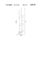
- FIG. 1 is a schematic representation of a pair of signals generated by a device of the type to be evaluated by the method and apparatus of this invention
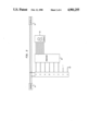
- FIG. 2 is a schematic representation of an apparatus in accordance with this invention.
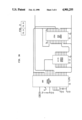
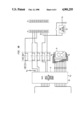
- FIG. 3 divided into FIG. 3A and FIG. 3B, is an alternate, more detailed, schematic representation of an apparatus in accordance with this invention.
- FIG. 1 illustrates a pattern of two wave train signals 10, 11 such as are generated by devices of the types with which this invention is concerned.
- Each signal 10, 11 isan electrical signal varying over time between two voltage levels and generally having the form of a square wave.
- Such wave train signals are generated by quadrature encoders such as those described briefly hereinabove.
- the two signals 10, 11 have a particular phase relation between them, and four separate types of changes between them may be identified. For a first time interval (at the extreme left side of FIG. 1), both signals are low. The one signal 10 goes high and one signal is high while the other is low. This state continues for a time interval identified as t1, after which the second signal 11 goes high.
- This state then continues for a time interval identified as t2, after which the firstsignal 10 goes low. This state then continues for a time interval identified as t3, after which the second signal goes low to return the pattern to its first state. This state continues for an interval identified as t4, and the pattern then repeats.
- the apparatus according to this invention is adapted for connection between an encoder 14 and a controller 15 which normally receives wave train signals from the encoder and uses them to read and display or control the physical position of a mechanical component.
- a controller 15 which normally receives wave train signals from the encoder and uses them to read and display or control the physical position of a mechanical component.
- the apparatus of this invention is contemplated as capable of evaluating the performance of a quadrature encoder which generates two electrical wave train signals indicative of the rotation of a shaft, generally as described above with reference to FIG. 1.
- the apparatus is equally capableof evaluating the performance of other devices generating wave train signals and of encoders coupled for sensing translation. It is only appropriate that each wave train signal vary between first and second states and the two wave train signals normally be out of phase one with the other.
- the contemplated apparatus has an appropriate electronic processor means and associated gate and register means for performing a series of functions under the control of appropriate instructions.
- Those functions include distinguishing, from a succession of changes of thetwo wave train signals between respective first and second states, four types of change of phase relation between the two wave train signals, as described above with reference to FIG. 1.
- the interval required for each type of phase change is timed, recorded in a register and accumulated into a predetermined plurality of sets of records of timed intervals for each of the four typesof change of phase relation between the two wave train signals.
- Means are provided for sensing the presence of each of the two wave train signals and for responding to the absence of the sensed presence of one wave trainsignal by interrupting the accumulation of sets of records and generating and displaying an error signal.
- means are provided for sensing theoccurrence of simultaneous changes in state in the two wave train signals and for responding to a sensed occurrence of such changes by interrupting the accumulation of sets of records and generating and displaying an errorsignal.
- errors if passed unnoticed, might permit an encoder having ascratched or partially obscured optical grating to be deemed acceptable.
- means are provided for sensing the sequence of changes in state in the two wave train signals and for responding to a sensed occurrence of a reversal in such sequence by interrupt in the accumulation of sets of records.
- the processor, gate and register means senses the accumulation of the predetermined plurality of sets of records and computes from the accumulated plurality of sets of records the mean time interval for a change of phase relation between the two wave train signals.
- the accumulation of sets of records may accumulate a set of sixtyfour successive changes and the time intervals required for those changes. The number accumulated is chosen to be a number divisible by four and is checked for that divisibility in order to assure that the accumulated set is proper. At each change, the states of the signals and the time since the last change are recorded.
- the attempted accumulation has occurred with an excessively fast rate of change of the phase relations between the signals and any attempted evaluation is likelyto be erroneous. Accordingly, any such accumulation is discarded without proceeding further and a new sampling begun.
- the time interval between phase changes is excessive, the attempted accumulation has occurred with an excessively slow rate of change of the phase relations between the signals and any attempted evaluation is likely to beerroneous. Accordingly, any such accumulation is discarded without proceeding further and a new sampling begun.
- the present invention contemplates that the two signals which aresupposedly inverse one to the other may be compared. If the relationship isnot properly inverse, then an error signal may be generated and displayed in order that an evaluator may know that the device is unacceptable.
- the processor sums the time intervals for all records registered and then divides by the predetermined number ofrecords accumulated. That computed mean time is then compared by an appropriate means with the accumulated sets of records of timed intervals and the one type of phase change for which the difference from the mean time interval is the greatest is determined. Means are then provided for computing a number indicative of the phase duration of that type of changeof phase which has the greatest difference from the mean time interval and for deriving, from the record of timed intervals which has the greatest difference from the mean time interval and the computed mean time interval, an encoder quality signal representative of the performance of the quadrature encoder generating the wave train signals. Stated in mathematical equations and referring to the illustration in FIG.
- the computations include: ##EQU1##Thus the quality signal will be understood to be a computed number representative of the phase difference least likely to be acceptable and may be displayed as a one digit number (on a scale of from 0 to 9) or a two digit number (on a scale of from 0 to 99) where a threshold of acceptability may be a quality of (for example only) 6 or 60. As will be understood, the maximum attainable quality should be a 9 or 90.
- the process of computation done by the electronic circuitry as described hereinabove may include certain rounding and smoothing steps where appropriate.
- the computation is accomplished using a processor means generally indicated at 16 in FIG. 2, which may be distributed among a number of known types of microcircuits or "chips" or possibly, through theuse of large scale integration technology or the like, formed into a singlededicated purpose microcomputer.
- the schematic of FIG. 3 illustrates the distribution of certain functions among such a plurality of known devices,including an 8085 processor indicated at 18 and an 81C55 display driver incorporating random access memory and indicated at 19.
- the quality signal derived by operation of the apparatus as described to this point is supplied to a suitable means for displaying theencoder quality signal.
- a suitable means for displaying theencoder quality signal takes the form of a display device 20 capable of showing a single digit in the rangeof from zero to nine, and thus adaptable to the range indicated above. Where a double digit indication is to be given, a second such display device is provided.
- the apparatus of this invention is connected with a wave train signal generating device or is interposed between a quadrature encoder anda controller as illustrated in FIG. 2. Thereafter, the encoder is caused togenerate signals, as by spinning the shaft of the encoder or moving the movable element of a translating encoder. As such mechanical movement occurs, at least two wave train signals are generated and supplied to the apparatus of this invention.
- the performance of the device or encoder is then evaluated by the steps of first distinguishing, from a succession of changes of the two wave train signals between respective first and second states, four types of change of phase relation between the two wave train signals.
- the method then proceeds by timing and recording the interval required for each type of phase change, and accumulating a predetermined plurality of sets of records of timed intervals for each of the four types of change of phase relation between the two wave train signals.
- the method includes sensing the presence of each of the two wave train signals, and responding to the absence of the sensed presence of one wave train signal by interrupting the accumulation of sets of records and generating and displaying an error signal.
- the method may also include sensing the occurrence of simultaneous changes in state in the two wave train signals, and responding to a sensed occurrenceof such changes by interrupting the accumulation of sets of records and generating and displaying an error signal.
- the method includes sensing the sequence of changes in state in the two wave train signals, and responding to a sensed occurrence of a reversal in such sequence by interrupting the accumulation of sets of records.
- the method then proceeds by computing from the accumulated plurality of sets of records the mean time interval for a change of phase relation between the two wave train signals; comparing the computed mean time interval with the accumulated sets of records of timed intervals and determining the one type of phase change for which the difference from themean time interval is the greatest; computing a number indicative of the phase duration of that type of change of phase which has the greatest difference from the mean time interval and deriving, from the record of timed intervals which has the greatest difference from the mean time interval and the computed mean time interval, and encoder quality signal representative of the performance and of quadrature encoder generating thewave train signals. That encoder quality signal is then used to drive a display for displaying the encoder quality signal.
- the present invention contemplates making, provision for communication of the quality signal to a remote sensing location, such as by the inclusion of an RS232 communication port in the apparatus of this invention. It is also possible, and contemplated by this invention, to process the data derived as described hereinabove in such ways as to determine other characteristics of encoders or the like, such as the distance through which the coupled mechanical movement has moved, or the direction, velocity, acceleration or jerk of such movements.
Abstract
Description
Claims (24)
Priority Applications (3)
| Application Number | Priority Date | Filing Date | Title |
|---|---|---|---|
| US07/171,473 US4901255A (en) | 1988-03-21 | 1988-03-21 | Method and apparatus for evaluating quadrature encoders |
| PCT/US1989/001134 WO1989009450A1 (en) | 1988-03-21 | 1989-03-20 | Method and apparatus for evaluating quadrature encoders |
| JP1504307A JPH03504159A (en) | 1988-03-21 | 1989-03-20 | Method and apparatus for evaluating quadrature encoders |
Applications Claiming Priority (1)
| Application Number | Priority Date | Filing Date | Title |
|---|---|---|---|
| US07/171,473 US4901255A (en) | 1988-03-21 | 1988-03-21 | Method and apparatus for evaluating quadrature encoders |
Publications (1)
| Publication Number | Publication Date |
|---|---|
| US4901255A true US4901255A (en) | 1990-02-13 |
Family
ID=22623860
Family Applications (1)
| Application Number | Title | Priority Date | Filing Date |
|---|---|---|---|
| US07/171,473 Expired - Lifetime US4901255A (en) | 1988-03-21 | 1988-03-21 | Method and apparatus for evaluating quadrature encoders |
Country Status (3)
| Country | Link |
|---|---|
| US (1) | US4901255A (en) |
| JP (1) | JPH03504159A (en) |
| WO (1) | WO1989009450A1 (en) |
Cited By (5)
| Publication number | Priority date | Publication date | Assignee | Title |
|---|---|---|---|---|
| US5118932A (en) * | 1990-11-13 | 1992-06-02 | Hughes Aircraft Company | Shaft rotation rate sensor with a diffraction grating producing a velocity-related beat frequency |
| US5406267A (en) * | 1991-07-22 | 1995-04-11 | Curtis; Stephen J. | Method and apparatus for the monitoring of the operation of linear and rotary encoders |
| WO2002004895A2 (en) * | 2000-07-07 | 2002-01-17 | Fluidsense Corporation | Optical position sensor and position determination method |
| US7066591B2 (en) | 2004-02-14 | 2006-06-27 | Hewlett-Packard Development Company, L.P. | Analog encoder |
| CN109883465A (en) * | 2017-12-06 | 2019-06-14 | 上海三菱电梯有限公司 | Encoder detection method |
Families Citing this family (2)
| Publication number | Priority date | Publication date | Assignee | Title |
|---|---|---|---|---|
| DE10041092A1 (en) * | 2000-08-22 | 2002-03-07 | Bosch Gmbh Robert | Method for correcting a phase angle when scanning a code track |
| US8339556B2 (en) | 2008-03-03 | 2012-12-25 | Hitachi Displays, Ltd. | Electro-optical device and display device with interdigital electrode portions on at least first and second substrates which are non-overlapping in a direction normal to the substrates |
Citations (13)
| Publication number | Priority date | Publication date | Assignee | Title |
|---|---|---|---|---|
| US3906361A (en) * | 1973-09-26 | 1975-09-16 | Us Air Force | Digital phase measuring system |
| US3953794A (en) * | 1975-03-27 | 1976-04-27 | Motorola Inc. | Digital phase detector |
| US4001682A (en) * | 1972-09-28 | 1977-01-04 | Cubic Corporation | Ambiguity free digital averaging phase meter |
| US4085362A (en) * | 1976-05-10 | 1978-04-18 | Stone-Platt Crawley Limited | Check synchronism |
| US4119910A (en) * | 1976-03-18 | 1978-10-10 | Shin Shirasuna Electric Corp. | Method and apparatus for detecting whether phase difference between two signals is constant |
| US4128812A (en) * | 1977-08-09 | 1978-12-05 | The United States Of America As Represented By The Secretary Of The Army | Phase discriminator |
| US4400664A (en) * | 1981-05-26 | 1983-08-23 | Motorola, Inc. | Digital phase detector |
| US4426620A (en) * | 1981-09-23 | 1984-01-17 | The United States Of America As Represented By The United States Department Of Energy | Analog quadrature signal to phase angle data conversion by a quadrature digitizer and quadrature counter |
| US4496936A (en) * | 1982-06-04 | 1985-01-29 | Atari, Inc. | Digital-analog conversion for shaft encoders |
| US4600994A (en) * | 1982-10-06 | 1986-07-15 | Takeda Riken Kogyo Kabushikikaisha | Phase difference measuring apparatus |
| US4636719A (en) * | 1984-11-01 | 1987-01-13 | Environmental Research Institute Of Michigan | Apparatus for extended precision phase measurement |
| US4700129A (en) * | 1985-08-30 | 1987-10-13 | Anritsu Corporation | Phase measurement apparatus with automatic calibration |
| US4754216A (en) * | 1987-09-03 | 1988-06-28 | National Semiconductor Corporation | Method and apparatus for qualifying the decode window margin of a phase locked loop data synchronizer |
-
1988
- 1988-03-21 US US07/171,473 patent/US4901255A/en not_active Expired - Lifetime
-
1989
- 1989-03-20 JP JP1504307A patent/JPH03504159A/en active Pending
- 1989-03-20 WO PCT/US1989/001134 patent/WO1989009450A1/en unknown
Patent Citations (13)
| Publication number | Priority date | Publication date | Assignee | Title |
|---|---|---|---|---|
| US4001682A (en) * | 1972-09-28 | 1977-01-04 | Cubic Corporation | Ambiguity free digital averaging phase meter |
| US3906361A (en) * | 1973-09-26 | 1975-09-16 | Us Air Force | Digital phase measuring system |
| US3953794A (en) * | 1975-03-27 | 1976-04-27 | Motorola Inc. | Digital phase detector |
| US4119910A (en) * | 1976-03-18 | 1978-10-10 | Shin Shirasuna Electric Corp. | Method and apparatus for detecting whether phase difference between two signals is constant |
| US4085362A (en) * | 1976-05-10 | 1978-04-18 | Stone-Platt Crawley Limited | Check synchronism |
| US4128812A (en) * | 1977-08-09 | 1978-12-05 | The United States Of America As Represented By The Secretary Of The Army | Phase discriminator |
| US4400664A (en) * | 1981-05-26 | 1983-08-23 | Motorola, Inc. | Digital phase detector |
| US4426620A (en) * | 1981-09-23 | 1984-01-17 | The United States Of America As Represented By The United States Department Of Energy | Analog quadrature signal to phase angle data conversion by a quadrature digitizer and quadrature counter |
| US4496936A (en) * | 1982-06-04 | 1985-01-29 | Atari, Inc. | Digital-analog conversion for shaft encoders |
| US4600994A (en) * | 1982-10-06 | 1986-07-15 | Takeda Riken Kogyo Kabushikikaisha | Phase difference measuring apparatus |
| US4636719A (en) * | 1984-11-01 | 1987-01-13 | Environmental Research Institute Of Michigan | Apparatus for extended precision phase measurement |
| US4700129A (en) * | 1985-08-30 | 1987-10-13 | Anritsu Corporation | Phase measurement apparatus with automatic calibration |
| US4754216A (en) * | 1987-09-03 | 1988-06-28 | National Semiconductor Corporation | Method and apparatus for qualifying the decode window margin of a phase locked loop data synchronizer |
Cited By (7)
| Publication number | Priority date | Publication date | Assignee | Title |
|---|---|---|---|---|
| US5118932A (en) * | 1990-11-13 | 1992-06-02 | Hughes Aircraft Company | Shaft rotation rate sensor with a diffraction grating producing a velocity-related beat frequency |
| US5406267A (en) * | 1991-07-22 | 1995-04-11 | Curtis; Stephen J. | Method and apparatus for the monitoring of the operation of linear and rotary encoders |
| WO2002004895A2 (en) * | 2000-07-07 | 2002-01-17 | Fluidsense Corporation | Optical position sensor and position determination method |
| WO2002004895A3 (en) * | 2000-07-07 | 2002-04-11 | Fluidsense Corp | Optical position sensor and position determination method |
| US7066591B2 (en) | 2004-02-14 | 2006-06-27 | Hewlett-Packard Development Company, L.P. | Analog encoder |
| CN109883465A (en) * | 2017-12-06 | 2019-06-14 | 上海三菱电梯有限公司 | Encoder detection method |
| CN109883465B (en) * | 2017-12-06 | 2021-10-01 | 上海三菱电梯有限公司 | Encoder detection method |
Also Published As
| Publication number | Publication date |
|---|---|
| WO1989009450A1 (en) | 1989-10-05 |
| JPH03504159A (en) | 1991-09-12 |
Similar Documents
| Publication | Publication Date | Title |
|---|---|---|
| US5088055A (en) | Coordinate measuring apparatus having a stylus friction compensating means | |
| US4794251A (en) | Apparatus for measuring lengths or angles | |
| CN100437027C (en) | Method of calibrating a coordinate positioning apparatus | |
| US4831510A (en) | Encoder and resolver signal processing circuit | |
| EP0666520B1 (en) | Position detecting method and apparatus | |
| US5301005A (en) | Method and apparatus for determining the position of a retroreflective element | |
| JPS57158829A (en) | Production of glasses | |
| EP0111642B1 (en) | Method and apparatus for measuring a displacement of one member relative to another | |
| US4901255A (en) | Method and apparatus for evaluating quadrature encoders | |
| US3987278A (en) | Moving object identifying system | |
| US5239297A (en) | Position-encoded screw and method and system for calibrating a position-encoded screw | |
| US7359826B2 (en) | Method and device for detection of oscillations by a position measuring system | |
| JP2635913B2 (en) | Length measuring or angle measuring method | |
| US4823000A (en) | Apparatus for indicating the value of a variable | |
| US5781282A (en) | Distance measurement device | |
| JPH03156339A (en) | Apparatus for measuring deviation of tooth of gear | |
| JPH05196451A (en) | Length measuring or angle measuring device | |
| JP2678386B2 (en) | Position detection device | |
| GB2208936A (en) | Method of and apparatus for conducting a run-out velocity and acceleration test on a surface | |
| EP0328611A1 (en) | Signal processing apparatus | |
| JPH0478984A (en) | Conveying speed measuring system for magnetic card | |
| JPH03272412A (en) | Angle measuring method and speed measuring apparatus | |
| SU1672377A1 (en) | Method for measuring velocity of conductor through which current is passed | |
| JPH0244002B2 (en) | ||
| SU1013745A1 (en) | Device for checking articles having threaded surface |
Legal Events
| Date | Code | Title | Description |
|---|---|---|---|
| AS | Assignment |
Owner name: LYNN ELECTRONICS CORPORATION, CHARLOTTE, COUNTY OF Free format text: ASSIGNMENT OF ASSIGNORS INTEREST.;ASSIGNOR:FOX, GLENN B.;REEL/FRAME:004878/0215 Effective date: 19880301 Owner name: LYNN ELECTRONICS CORPORATION, CHARLOTTE, COUNTY OF Free format text: ASSIGNMENT OF ASSIGNORS INTEREST.;ASSIGNOR:JENRETTE, WILLIAM I.;REEL/FRAME:004878/0237 Effective date: 19880222 Owner name: LYNN ELECTRONICS CORPORATION, CHARLOTTE, COUNTY OF Free format text: ASSIGNMENT OF ASSIGNORS INTEREST.;ASSIGNOR:LYNN, JOHN S.;REEL/FRAME:004878/0240 Effective date: 19880222 Owner name: LYNN ELECTRONICS CORPORATION, A NC CORP., NORTH CA Free format text: ASSIGNMENT OF ASSIGNORS INTEREST;ASSIGNOR:FOX, GLENN B.;REEL/FRAME:004878/0215 Effective date: 19880301 Owner name: LYNN ELECTRONICS CORPORATION, A NC CORP., NORTH CA Free format text: ASSIGNMENT OF ASSIGNORS INTEREST;ASSIGNOR:JENRETTE, WILLIAM I.;REEL/FRAME:004878/0237 Effective date: 19880222 Owner name: LYNN ELECTRONICS CORPORATION, A NC CORP., NORTH CA Free format text: ASSIGNMENT OF ASSIGNORS INTEREST;ASSIGNOR:LYNN, JOHN S.;REEL/FRAME:004878/0240 Effective date: 19880222 |
|
| STCF | Information on status: patent grant |
Free format text: PATENTED CASE |
|
| FPAY | Fee payment |
Year of fee payment: 4 |
|
| SULP | Surcharge for late payment | ||
| FEPP | Fee payment procedure |
Free format text: PAYOR NUMBER ASSIGNED (ORIGINAL EVENT CODE: ASPN); ENTITY STATUS OF PATENT OWNER: SMALL ENTITY |
|
| FPAY | Fee payment |
Year of fee payment: 8 |
|
| FPAY | Fee payment |
Year of fee payment: 12 |