US4901104A - Image recording apparatus - Google Patents
Image recording apparatus Download PDFInfo
- Publication number
- US4901104A US4901104A US07/196,977 US19697788A US4901104A US 4901104 A US4901104 A US 4901104A US 19697788 A US19697788 A US 19697788A US 4901104 A US4901104 A US 4901104A
- Authority
- US
- United States
- Prior art keywords
- photo
- halftone screen
- original
- recording medium
- sensitive recording
- Prior art date
- Legal status (The legal status is an assumption and is not a legal conclusion. Google has not performed a legal analysis and makes no representation as to the accuracy of the status listed.)
- Expired - Fee Related
Links
Images


Classifications
-
- G—PHYSICS
- G03—PHOTOGRAPHY; CINEMATOGRAPHY; ANALOGOUS TECHNIQUES USING WAVES OTHER THAN OPTICAL WAVES; ELECTROGRAPHY; HOLOGRAPHY
- G03F—PHOTOMECHANICAL PRODUCTION OF TEXTURED OR PATTERNED SURFACES, e.g. FOR PRINTING, FOR PROCESSING OF SEMICONDUCTOR DEVICES; MATERIALS THEREFOR; ORIGINALS THEREFOR; APPARATUS SPECIALLY ADAPTED THEREFOR
- G03F7/00—Photomechanical, e.g. photolithographic, production of textured or patterned surfaces, e.g. printing surfaces; Materials therefor, e.g. comprising photoresists; Apparatus specially adapted therefor
- G03F7/002—Photomechanical, e.g. photolithographic, production of textured or patterned surfaces, e.g. printing surfaces; Materials therefor, e.g. comprising photoresists; Apparatus specially adapted therefor using materials containing microcapsules; Preparing or processing such materials, e.g. by pressure; Devices or apparatus specially designed therefor
- G03F7/0022—Devices or apparatus
-
- G—PHYSICS
- G03—PHOTOGRAPHY; CINEMATOGRAPHY; ANALOGOUS TECHNIQUES USING WAVES OTHER THAN OPTICAL WAVES; ELECTROGRAPHY; HOLOGRAPHY
- G03B—APPARATUS OR ARRANGEMENTS FOR TAKING PHOTOGRAPHS OR FOR PROJECTING OR VIEWING THEM; APPARATUS OR ARRANGEMENTS EMPLOYING ANALOGOUS TECHNIQUES USING WAVES OTHER THAN OPTICAL WAVES; ACCESSORIES THEREFOR
- G03B27/00—Photographic printing apparatus
- G03B27/32—Projection printing apparatus, e.g. enlarger, copying camera
-
- G—PHYSICS
- G03—PHOTOGRAPHY; CINEMATOGRAPHY; ANALOGOUS TECHNIQUES USING WAVES OTHER THAN OPTICAL WAVES; ELECTROGRAPHY; HOLOGRAPHY
- G03B—APPARATUS OR ARRANGEMENTS FOR TAKING PHOTOGRAPHS OR FOR PROJECTING OR VIEWING THEM; APPARATUS OR ARRANGEMENTS EMPLOYING ANALOGOUS TECHNIQUES USING WAVES OTHER THAN OPTICAL WAVES; ACCESSORIES THEREFOR
- G03B2227/00—Photographic printing apparatus
- G03B2227/32—Projection printing apparatus, e.g. enlarging apparatus, copying camera
- G03B2227/325—Microcapsule copiers
Definitions
- This invention relates to an image recording apparatus for recording an image onto a photo-sensitive recording medium in accordance with given image information.
- An image recording apparatus of the kind referred to above is conventionally known, in which a light is applied to an original, and the light reflected by or transmitted through the original is caused to pass through an optical system including a reflecting mirror, an optical filter, lenses and the like. A photo-sensitive recording medium is exposed to the light by the optical system, so that a latent image corresponding to an image on the original is formed on the photo-sensitive recording medium.
- the photo-sensitive recording medium high in gamma value is employed in which a color-development concentration changes abruptly with respect to a light exposure so that a contrasty image can be recorded on the photo-sensitive recording medium.
- a halftone screen having a dot pattern is arranged on an optical path extending between the original and the photo-sensitive recording medium, to expose the recording medium to the light having passed through the halftone screen.
- the exposure of the light transmitted through one of transparent portions of the halftone screen and arriving at the photo-sensitive recording medium varies depending upon the darks and lights of the image on the original as indicated respectively by (a) and (b) in FIG. 13.
- a portion on the recording medium, at which the light arrives is developed with a constant concentration so that the darks and lights of the image on the original are replaced respectively by a large spot and a small spot as indicated respectively by (c) and (d) in FIG. 13.
- the difference between the darks and lights of the image on the original is expressed as an area gradation by the size and distribution density of dots.
- the halftone screen is employed when the image on the original is of a continuous tone, the gradation of the image recorded on the photo-sensitive recording medium is improved.
- the halftone screen is employed for the original in which the lights and darks of the image on the original are expressed by dots different in size from each other, interference between the dots of the image on the original and the halftone screen causes interference fringes or moire to be formed on the image recorded onto the photo-sensitive recording medium. This raises such a problem that the image recorded onto the recording medium becomes blurred.
- an apparatus for recording an image on an original onto a photo-sensitive recording medium high in gamma value which comprises:
- light source means for emitting a light with which the original is illuminated, the light from the light source means passing along a predetermined optical path extending between the light source means and the photo-sensitive recording medium;
- an optical system arranged on the predetermined optical path for exposing the photo-sensitive recording medium to the light from the original to form an image on the photo-sensitive recording medium, which image corresponds to the image on the original;
- halftone screen means having its light transmittance varying regularly, the halftone screen means being arranged on the optical path for movement therealong between an operative position where a screening effect of the halftone screen means is validated and an inoperative position where the screening effect of the halftone screen means is invalidated;
- control means for controlling the moving means in such a manner that when the image on the original is of a continuous tone, the moving means moves the halftone screen means to the operative position, while when the image on the original is of a dot tone, the moving means moves the halftone screen means to the inoperative position.
- the image recording apparatus With the arrangement of the image recording apparatus according to the invention, it is possible to record, onto the photo-sensitive recording medium, an image which is always sharp and high in gradation, in accordance with the type of the image on the original.
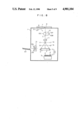
- FIG. 1 is a schematic structural view of a color image recording apparatus embodying the invention
- FIG. 2 is an exaggerated fragmental cross-sectional view of a photo and pressure sensitive recording sheet employed in the apparatus illustrated in FIG. 1;
- FIG. 3 is a graphical representation of a characteristic curve showing a change in color-development concentration with respect to an exposure of light to which the photo and pressure sensitive recording sheet illustrated in FIG. 2 is exposed;
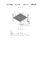
- FIG. 4 is a perspective view of a halftone screen employed in the apparatus illustrated in FIG. 1, and a mechanism for adjusting a position of the halftone screen, with dots on the screen shown exaggeratedly;
- FIG. 5 is a graphical representation of a transmittance of the halftone screen along line V--V in FIG. 4, with the waveform shown exaggeratedly;
- FIG. 6a is a view showing the intensity of a light transmitted through a sectoral filter section for cyan, of a color separating filter
- FIG. 6b is a view showing an exposure distribution on the photo and pressure sensitive recording sheet exposed to the light transmitted through the halftone screen;
- FIG. 7 is a view showing a color-development concentration distribution of a red color on the photo and pressure sensitive recording sheet
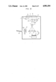
- FIG. 8 is a schematic structural view of a modification of the apparatus.
- FIG. 9 is a perspective view of a halftone screen employed in modification illustrated in FIG. 8.
- FIG. 10 is a graphical representation of a transmittance of the halftone screen along line X--X in FIG. 9;
- FIG. 11 is a schematic structural view of another modification of the apparatus.
- FIG. 12 is a schematic structural view of still another modification of the apparatus.
- FIG. 13 is a view for explanation of a manner in which dots are formed on the photo-sensitive recording medium when a halftone screen is employed.
- a color image recording apparatus embodying the invention which comprises a body 1.
- a sheet feed cassette 3 is arranged at a lower location within the body 1.
- a stack of photo and pressure sensitive recording sheets 2 serving as a photo-sensitive recording medium is accommodated in the sheet feed cassette 3.
- the recording sheets 2 are adapted to be fed one by one by a sheet feed roller 4 and the like, onto an exposure platen 5 in the form of an endless belt.
- the photo and pressure sensitive recording sheet 2 is composed of a sheet of substrate or carrier 2a and microcapsules coated on one side of the carrier 2a.
- the microcapsules include cyan microcapsules 2C primarily containing a cyan dye precursor, magenta microcapsules 2M primarily containing a magenta dye precursor, and yellow microcapsules 2Y primarily containing a yellow dye precursor.
- Each of the microcapsules 2C, 2M and 2Y also contains a photo-curable resin, a photo-sensitizer, a photo-polymerization initiator and the like.
- the one side of the carrier 2a is coated also with a developing agent which reacts with the dye precursors contained in the microcapsules 2C, 2M and 2Y to develop the color.
- FIG. 3 shows a characteristic curve or a so-called sensitometry curve representative of a change in color-development concentration with respect to the exposure of light to which the photo and pressure sensitive recording sheet 2 is exposed.
- An original platen 6 formed of a transparent glass is mounted in the top wall of the body 1 for reciprocative movement in the horizontal plane in a known manner.
- An original cover 8 is provided for covering an original 7 resting on the original platen 6.
- a lamp 9 serving as a light source emitting a light to scan a downwardly facing side of the original 7.
- the light from the lamp 9 is adapted to pass along a predetermined optical path L extending between the lamp 9 and the photo and pressure sensitive recording sheet 2 on the exposure platen 5.
- the optical system comprises a three-color separating filter 10 and an imaging lens 11.
- a halftone screen 12 is arranged on the optical path L and between the imaging lens 11 and the recording sheet 2 on the exposure platen 5.
- the three-color separating filter 10 is composed of three sectoral filter sections including a red sectoral filter section 10C for cyan through which only the light having wavelengths sensible by the cyan microcapsules 2C is allowed to pass, a green sectoral filter section 10M for magenta through which only the light having wavelengths sensible by the magenta microcapsules 2M is allowed to pass, and a blue sectoral filter section 10Y for yellow through which only the light having wavelengths sensible by the yellow microcapsules 2Y is allowed to pass.
- a red sectoral filter section 10C for cyan through which only the light having wavelengths sensible by the cyan microcapsules 2C is allowed to pass
- a green sectoral filter section 10M for magenta through which only the light having wavelengths sensible by the magenta microcapsules 2M is allowed to pass
- a blue sectoral filter section 10Y for yellow through which only the light having wavelengths sensible by the yellow microcapsules 2Y is allowed to pass.
- the halftone screen 12 employed in the illustrated embodiment is one generally called a contact screen.
- the halftone screen 12 has a multiplicity of minute dots arranged in the form of a checkered pattern on a transparent resinous substrate at a distribution density of 175 per inch so that the lights and darks vary continuously.
- the halftone screen 12 has its light transmittance T 1 which varies continuously in the form of a sinusoidal curve as shown in FIG. 5.
- T 1 which varies continuously in the form of a sinusoidal curve as shown in FIG. 5.
- a screening effect of the halftone screen 12 is validated when it is located in close relation to the photo and pressure sensitive recording sheet 2, but the screening effect is invalidated when the halftone screen 12 is located apart from the recording sheet 2.
- the size of the dots in FIG. 4 and the size of the waveform indicative of the transmittance in FIG. 5 are shown exaggeratedly.
- moving means comprised of a position adjusting mechanism 13 is associated with the halftone screen 12 for moving the same along the optical path L between an operative position located in close relation to the photo and pressure sensitive recording sheet 2 on the exposure platen 5 as indicated by the solid line in FIG. 1, and an inoperative position located approximately 5 to 60 mm apart away from the recording sheet 2 as indicated by the phantom line in FIG. 1.
- the screening effect of the halftone screen 12 is validated, while in the inoperative position, the screening effect of the halftone screen 12 is invalidated.
- the position adjusting mechanism 13 comprises a pair of support members 14 and 14 which support respectively opposite side edges of the halftone screen 12.
- the support members 14 and 14 are mounted respectively on a vertical guide rod 15 and a vertical screw rod 16 for movement therealong.
- the screw rod 16 is drivingly connected to a stepping motor 17 through a pair of gear wheels 18 and 19.
- the support members 14 and 14 are moved together with the halftone screen 12 along the guide rod 15 and the screw rod 16.
- Control means associated with the stepping motor 17 comprises a CPU (central processing unit) 20 electrically connected to the stepping motor 17 and a selector switch SW 1 electrically connected to the CPU 20.
- CPU central processing unit
- the selector switch SW 1 is arranged on an operating panel (not shown) on the top wall of the body 1 and is selectively movable between a continuous-tone position and a dot-tone position.
- the arrangement is such that when the selector switch SW 1 is moved to the continuous-tone position, the CPU 20 controls the stepping motor 17 so as to move the halftone screen 12 to the operative position, while when the selector switch SW 1 is moved to the dot-tone position, the CPU 20 controls the stepping motor 17 so as to move the halftone screen 12 to the inoperative position.
- the original 7 on the original platen 6 is illuminated with the light from the lamp 9.
- the light reflected by the original 7 is caused to pass through the selected sectoral filter section of the color separating filter 10, the imaging lens 11 and the halftone screen 12.
- the photo and pressure sensitive recording sheet 2 on the exposure platen 5 is exposed to the light reflected from the original 7 in such a manner that only one of the three groups of microcapsules 2C, 2M and 2Y, corresponding to the selected filter sectoral section, is photo-cured by the light in accordance with the image on the original 7.
- the remaining two filter sectoral sections are successively located on the optical path L, and the remaining two groups of microcapsules are successively photo-cured respectively by the lights transmitted through the respective remaining two sectoral filter sections.
- three color-decomposed latent images are formed on the recording sheet 2 in accordance with the image on the original 7.
- a developing unit 21 for developing the latent images on the photo and pressure sensitive recording sheet 2 is arranged on the left-hand side of the exposure platen 5 as viewed in FIG. 1.
- the developing unit 21 comprises a pair of pressure-developing rollers 21a and 21b.
- the recording sheet 2 after having been subjected to the predetermined exposure processing on the exposure platen 5 is transported by running of the exposure platen 5 into the nip between the pair of pressure-developing rollers 21a and 21b of the developing unit 21.
- the recording sheet 2 is caused to pass under pressure through the nip between the pressure-developing rollers 21a and 21b to rupture the microcapsules 2C, 2M and 2Y remaining uncured, so that the dye precursors are squeezed out of the ruptured microcapsules.
- the dye precursors squeezed out of the ruptured microcapsules react with the developing agent to develop the latent images on the recording sheet 2.
- a color image is formed on the recording sheet 2.
- the recording sheet 2 having formed thereon the color image is transported by rotation of the pressure-developing rollers 21a and 21b and is discharged onto a tray 22.
- the selector switch SW 1 is moved to the continuous-tone position.
- the CPU 20 controls rotation of the stepping motor 17 so as to move the halftone screen 12 to the operative position indicated by the solid line in FIG. 1 where the halftone screen 12 is located in close relation to the recording sheet 2 on the exposure platen 5.
- the halftone screen 12 With the halftone screen 12 located in the operative position, latent images corresponding respectively to cyan, magenta and yellow are formed, in the mentioned order, on the recording sheet 2 on the exposure platen 5. Specifically, the recording sheet 2 is fed from the sheet feed cassette 3 onto the exposure platen 5, and the three-color separating filter 10 is angularly moved successively in such a manner that the sectoral filter section 10C for cyan is first located on the optical path L, the sectoral filter section 10M for magenta is then located on the optical path L, and the sectoral filter section 10Y for yellow is lastly located on the optical path L.
- the lamp 9 is turned on each time one of the sectoral filter sections 10C, 10M and 10Y is located on the optical path L, to scan the downwardly facing side of the original 7.
- the sectoral filter section 10C located on the optical path L, of the light reflected by the original 7, only the wavelengths sensible by the cyan microcapsules 2C are allowed to pass through the sectoral filter section 10C.
- the reflected light having the wavelengths having passed through the sectoral filter section 10C is applied to the photo and pressure sensitive recording sheet 2 on the exposure platen 5 through the imaging lens 11 and the halftone screen 12. That is, supposing that the reflected light having transmitted through the sectoral filter section 10C for cyan has the light intensity L 1 which varies continuously from 0 to 100% as shown in FIG.
- the recording sheet 2 is exposed to the reflected light in such a fashion that passage of the reflected light through the halftone screen 12 causes a change in the light intensity L 1 to be replaced by dots different in size from each other.
- the intensity L 1 of the reflected light is low, exposed portions on the recording sheet 2 are represented by spots small in area.
- the exposed portions on the recording sheet 2 are represented by spots gradually increasing in area.
- the recording sheet 2 is exposed in such a fashion that exposed portions and unexposed portions form a checkered pattern.
- exposed portions increase in area, while unexposed portions are represented by spots small in area.
- the exposed portions are indicated in a painted-out manner.
- the cyan microcapsules 2C in the regions on the recording sheet 2 corresponding to the red portions of the image on the original 7 are photo-cured to form a latent image on the recording sheet 2.
- Exposure of the magenta and yellow microcapsules 2M and 2Y is carried out in a manner similar to that described above. Specifically, with the sectoral filter section 10M for magenta or the sectoral filter section 10Y for yellow is selectively located on the optical path L, the lamp 9 is turned on to illuminate the original 7. Only the light having wavelengths sensible by the magenta microcapsules 2M or the yellow microcapsules 2Y is allowed to pass through the sectoral filter section, so that a latent image corresponding to green or blue portions of the image on the original 7 is formed in the form of dots on the recording sheet 2. These latent images corresponding respectively to red, green and blue are formed on the recording sheet 2 in a superposed fashion.
- the photo and pressure sensitive recording sheet 2 is caused to pass under pressure through the nip between the pressure-developing rollers 21a and 21b to rupture the microcapsules 2C, 2M and 2Y remaining uncured, so that the dye precursors are squeezed out of the ruptured microcapsules.
- the dye precursors squeezed out of the ruptured microcapsules react with the developing agent so that the color image is brought out on the recording sheet 2.
- the recording sheet 2 having formed thereon the color image is discharged onto the tray 22 by rotation of the pressure-developing rollers 21a and 21b.
- the cyan microcapsules 2C are photo-cured in the regions on the recording sheet 2 which are exposed to the red light from the original 7.
- the magenta and yellow microcapsules 2M and 2Y are ruptured so that the magenta and yellow dye precursors react with the developing agent to produce the red color.
- the lights and darks of the red color are represented by the size and distribution density of red dots.
- the yellow and cyan microcapsules 2Y and 2C are ruptured so that the yellow and cyan dye precursors react with the developing agent to produce the green color.
- the selector switch SW 1 is moved to the dot-tone position.
- the stepping motor 17 is rotatively driven under the control of the CPU 20, to move the halftone screen 12 to the inoperative position spaced apart from the recording sheet 2, as indicated by the phantom line in FIG. 1.
- the recording sheet 2 With the halftone screen 12 located at the inoperative position, the recording sheet 2 is exposed successively to the lights transmitted respectively through the sectoral filter sections 10C, 10M and 10Y for cyan, magenta and yellow, in the mentioned order, in a manner like that for the aforesaid image of the continuous tone. Since the halftone screen 12 is located at the inoperative position, three color-decomposed latent images are formed on the recording sheet 2, in the form of dots corresponding to the dots of the image on the original 7.
- the recording sheet 2 having formed thereon the latent images is caused to pass under pressure through the nip between the pressure-developing rollers 21a and 21b to develop the latent images, in a manner like that for the image of the continuous tone. Subsequently, the recording sheet 2 is discharged onto the tray 22.
- the halftone screen 12 arranged between the recording sheet 2 on the exposure platen 5 and the imaging lens 11 is located at the operative position close to the recording sheet 2 where the screening effect of the halftone screen 12 is validated, so that a sharp and high gradation image, in which a difference between the lights and darks is clear, can be recorded onto the recording sheet 2.
- the halftone screen 12 is located at the inoperative position where the screening effect of the halftone screen 12 is invalidated, so that a sharp image can be recorded onto the recording sheet 2 without occurrence of interference fringes due to interference between the dots of the image on the original 7 and the halftone screen 12.
- FIGS. 8 through 10 A modification of the image recording apparatus will be described with reference to FIGS. 8 through 10.
- components and parts like or similar to those of the embodiment illustrated in FIGS. 1 through 7 are designated by like or similar reference numerals, and the detailed description of such like or similar components and parts will therefore be omitted to avoid repetition.
- the modification is different from the previously mentioned embodiment in that a halftone screen 31 having a cross stripe pattern shown in FIG. 9 is employed in substitution for the halftone screen 12.
- the halftone screen 31 is one generally called a glass screen in which a first group of a multiplicity of black lines extending in parallel relation to each other are intersected at right angles with a second group of multiplicity of black lines extending in parallel relation to each other.
- the black lines in each of the first and second groups are equidistantly spaced from each other at intervals of 120 per inch.
- the halftone screen 31 has its transmittance T 2 which varies continuously in the form of a rectangular wave.
- the halftone screen 31 when the halftone screen 31 is arranged between the imaging lens 11 and the photo and pressure sensitive recording sheet 2 to record an image of the continuous tone on the original 7 onto the recording sheet 2, the halftone screen 31 is located at an operative position spaced the predetermined distance apart from the recording sheet 2 on the exposure platen 5 as indicated by the solid line in FIG. 8.
- the halftone screen 31 when the image of a dot tone on the original 7 is recorded onto the recording sheet 2, the halftone screen 31 is located at an inoperative position spaced apart from the recording sheet 2 a distance longer than the predetermined distance, as indicated by the phantom line in FIG. 8.
- FIGS. 11 and 12 show respectively another and still another modifications of the image recording apparatus according to the invention.
- components and parts like or similar to those of the embodiment illustrated in FIGS. 1 through 7 are designated by like or similar reference numerals, and the detailed description of such like or similar components and parts will therefore be omitted for simplification.
- the modification illustrated in FIG. 11 employs a transmitted-light exposure system, in substitution for the reflected-light exposure system of the embodiment illustrated in FIG. 1 in which the light is applied to the original 7 and the recording sheet 2 is exposed to the light reflected from the original 7.
- a reflector 141 is provided for reflecting the light from the lamp 9 toward a condenser lens 142.
- a transparent original 107 such as a slide is illuminated with the light passing through the condenser lens 142.
- the light is transmitted through the transparent original 107 and passes along the predetermined optical path L.
- the recording sheet 2 is exposed to the light transmitted through the transparent original 107.
- the halftone screen 12 is arranged between the lamp 9 and the original 7, unlike the embodiment shown in FIG. 1 in which the halftone screen 12 is arranged between the imaging lens 11 and the recording sheet 2 on the exposure platen 5.
- the operative position of the halftone screen 12 in the modification of FIG. 12 is located remote from the original 7 on the original platen 6, while the inoperative position of the halftone screen 12 is located adjacent the original 7. It is needless to say that the halftone screen 13 shown in FIG. 8 can be substituted for the halftone screen 12 illustrated in FIG. 12.
- each dot on the halftone screen 12 may be in the form of a circle, a rhomboid or the like, other than the square.
- the halftone screen 12 may have dots different in size or distribution density from the illustrated ones.
- the spacing between each pair of adjacent black lines and the intersecting angle between the first and second groups of black lines on the halftone screen 31 may suitably be modified.
- the halftone screen 12 or 31 may be so arranged as to be angularly moved in the horizontal plane intermittently by a minute angle.
- each photo and pressure sensitive recording sheet may be employed, in which each photo and pressure sensitive recording sheet has coated thereon with only the microcapsules 2C, 2M and 2Y corresponding to the respective colors, while a developing agent is coated on each separate transfer sheet.
- each of the microcapsules coated on the recording sheet 2 may contain a resin capable of being photo-softened such that the microcapsules are photo-softened at exposure. In this case, it is required to employ a three-color separating filter which selectively absorbs only a light of wavelengths photo-softening the microcapsules.
- Photo and heat sensitive recording sheets, silver chloride photographing sheets or other photo-sensitive recording sheets may be used in substitution for the photo and pressure sensitive recording sheets 2.
- a continuous roll of photo and pressure sensitive web may be employed in substitution for the cut recording sheets 2.
- the photo and pressure sensitive recording sheet may be coated with microcapsules which contain only one of individual dye precursors for black, yellow, magenta and cyan to provide a single-color image recording apparatus.
- the color-separating filter 10 may have a fourth sectoral filter section which allows passage of a light having wavelengths sensible by all the microcapsules 2C, 2M and 2Y on the photo and pressure sensitive recording sheet 2.
- the halftone screen 12 is once located at the inoperative position to expose the recording sheet 2 to the light, thereby shortening a period of time for the pre-exposure until the microcapsules 2C, 2M and 2Y initiate photo-curing, or thereby improving the gradation reproducibility of the highlight portions of the original 7.
Abstract
Description
Claims (12)
Applications Claiming Priority (2)
| Application Number | Priority Date | Filing Date | Title |
|---|---|---|---|
| JP62-127482 | 1987-05-25 | ||
| JP62127482A JPS63291048A (en) | 1987-05-25 | 1987-05-25 | Exposing device |
Publications (1)
| Publication Number | Publication Date |
|---|---|
| US4901104A true US4901104A (en) | 1990-02-13 |
Family
ID=14961031
Family Applications (1)
| Application Number | Title | Priority Date | Filing Date |
|---|---|---|---|
| US07/196,977 Expired - Fee Related US4901104A (en) | 1987-05-25 | 1988-05-20 | Image recording apparatus |
Country Status (2)
| Country | Link |
|---|---|
| US (1) | US4901104A (en) |
| JP (1) | JPS63291048A (en) |
Cited By (4)
| Publication number | Priority date | Publication date | Assignee | Title |
|---|---|---|---|---|
| US5019866A (en) * | 1989-10-11 | 1991-05-28 | Eastman Kodak Company | Pressurized screen assembly for exposure of a continuous tone image |
| US5055877A (en) * | 1989-01-09 | 1991-10-08 | Sharp Kabushiki Kaisha | Copying apparatus with moveable screen and method |
| US5408296A (en) * | 1991-04-23 | 1995-04-18 | Fuji Photo Film Co., Ltd. | Color proof making apparatus |
| US5884114A (en) * | 1996-10-24 | 1999-03-16 | Brother Kogyo Kabushiki Kaisha | Image forming device |
Citations (2)
| Publication number | Priority date | Publication date | Assignee | Title |
|---|---|---|---|---|
| US2740323A (en) * | 1952-07-22 | 1956-04-03 | Donnelley & Sons Co | Color separation apparatus |
| US3335636A (en) * | 1964-12-31 | 1967-08-15 | Edward R Atkinson | Fully automated process camera |
-
1987
- 1987-05-25 JP JP62127482A patent/JPS63291048A/en active Pending
-
1988
- 1988-05-20 US US07/196,977 patent/US4901104A/en not_active Expired - Fee Related
Patent Citations (2)
| Publication number | Priority date | Publication date | Assignee | Title |
|---|---|---|---|---|
| US2740323A (en) * | 1952-07-22 | 1956-04-03 | Donnelley & Sons Co | Color separation apparatus |
| US3335636A (en) * | 1964-12-31 | 1967-08-15 | Edward R Atkinson | Fully automated process camera |
Cited By (4)
| Publication number | Priority date | Publication date | Assignee | Title |
|---|---|---|---|---|
| US5055877A (en) * | 1989-01-09 | 1991-10-08 | Sharp Kabushiki Kaisha | Copying apparatus with moveable screen and method |
| US5019866A (en) * | 1989-10-11 | 1991-05-28 | Eastman Kodak Company | Pressurized screen assembly for exposure of a continuous tone image |
| US5408296A (en) * | 1991-04-23 | 1995-04-18 | Fuji Photo Film Co., Ltd. | Color proof making apparatus |
| US5884114A (en) * | 1996-10-24 | 1999-03-16 | Brother Kogyo Kabushiki Kaisha | Image forming device |
Also Published As
| Publication number | Publication date |
|---|---|
| JPS63291048A (en) | 1988-11-28 |
Similar Documents
| Publication | Publication Date | Title |
|---|---|---|
| US4860058A (en) | Image forming apparatus | |
| US4920374A (en) | Picture recording apparatus | |
| US4272186A (en) | Camera method and apparatus for recording with selected contrast | |
| US3745235A (en) | Method and apparatus for the production of color prints on paper | |
| US4875074A (en) | Image recording apparatus | |
| EP0141850B1 (en) | Apparatus and method for electrophotographically producing color copy continuous-tone originals and other content of selective color | |
| US4901104A (en) | Image recording apparatus | |
| US4937592A (en) | Image recording--of recording sheets | |
| US4095888A (en) | Color electrophotography apparatus | |
| US4785316A (en) | Image recording device | |
| US5087938A (en) | Image recording apparatus | |
| US2049556A (en) | Color photography | |
| US5063405A (en) | Apparatus for forming images | |
| JP2927021B2 (en) | Image forming device | |
| US4157220A (en) | Technique for recording micropicture-information on a diffractive subtractive filter embossing master | |
| JPH0829884A (en) | Photograph printing device | |
| JPH0822086A (en) | Photographic printing device | |
| JPS62211673A (en) | Electrophotography recording device | |
| JPS63222857A (en) | Color image recorder | |
| JP2511512B2 (en) | Photosynthesis printing equipment | |
| JPH04275539A (en) | Image forming device | |
| JPH04344631A (en) | Shuttle type exposing device | |
| JPS63267554A (en) | Image recorder | |
| JPH01102448A (en) | Image forming device provided with auxiliary exposing device | |
| JPS6337338A (en) | Copying device |
Legal Events
| Date | Code | Title | Description |
|---|---|---|---|
| AS | Assignment |
Owner name: BROTHER KOGYO KABUSHIKI KAISHA, 35, HORITA-DORI 9- Free format text: ASSIGNMENT OF ASSIGNORS INTEREST.;ASSIGNOR:SAKAKIBARA, KENJI;REEL/FRAME:004892/0376 Effective date: 19880517 Owner name: BROTHER KOGYO KABUSHIKI KAISHA, JAPAN Free format text: ASSIGNMENT OF ASSIGNORS INTEREST;ASSIGNOR:SAKAKIBARA, KENJI;REEL/FRAME:004892/0376 Effective date: 19880517 |
|
| FEPP | Fee payment procedure |
Free format text: PAYOR NUMBER ASSIGNED (ORIGINAL EVENT CODE: ASPN); ENTITY STATUS OF PATENT OWNER: LARGE ENTITY |
|
| FEPP | Fee payment procedure |
Free format text: PAYOR NUMBER ASSIGNED (ORIGINAL EVENT CODE: ASPN); ENTITY STATUS OF PATENT OWNER: LARGE ENTITY Free format text: PAYER NUMBER DE-ASSIGNED (ORIGINAL EVENT CODE: RMPN); ENTITY STATUS OF PATENT OWNER: LARGE ENTITY |
|
| REMI | Maintenance fee reminder mailed | ||
| LAPS | Lapse for failure to pay maintenance fees | ||
| FP | Lapsed due to failure to pay maintenance fee |
Effective date: 19940213 |
|
| STCH | Information on status: patent discontinuation |
Free format text: PATENT EXPIRED DUE TO NONPAYMENT OF MAINTENANCE FEES UNDER 37 CFR 1.362 |