US4901008A - Circuit arrangement for testing the correct functioning of circuit(s) - Google Patents
Circuit arrangement for testing the correct functioning of circuit(s) Download PDFInfo
- Publication number
- US4901008A US4901008A US07/252,246 US25224688A US4901008A US 4901008 A US4901008 A US 4901008A US 25224688 A US25224688 A US 25224688A US 4901008 A US4901008 A US 4901008A
- Authority
- US
- United States
- Prior art keywords
- current
- core
- winding
- circuit arrangement
- circuit
- Prior art date
- Legal status (The legal status is an assumption and is not a legal conclusion. Google has not performed a legal analysis and makes no representation as to the accuracy of the status listed.)
- Expired - Lifetime
Links
- 238000012360 testing method Methods 0.000 title claims abstract description 25
- 238000004804 winding Methods 0.000 claims abstract description 29
- 230000004907 flux Effects 0.000 claims abstract description 17
- 230000005355 Hall effect Effects 0.000 claims abstract description 3
- 239000000463 material Substances 0.000 claims abstract description 3
- 230000001419 dependent effect Effects 0.000 claims description 3
- 230000002463 transducing effect Effects 0.000 claims 5
- 238000005259 measurement Methods 0.000 description 9
- 238000010586 diagram Methods 0.000 description 6
- 230000008859 change Effects 0.000 description 5
- 239000004020 conductor Substances 0.000 description 4
- 238000001514 detection method Methods 0.000 description 4
- 230000011664 signaling Effects 0.000 description 4
- 230000003247 decreasing effect Effects 0.000 description 3
- 230000001960 triggered effect Effects 0.000 description 2
- 230000036541 health Effects 0.000 description 1
- 238000005286 illumination Methods 0.000 description 1
- 230000004048 modification Effects 0.000 description 1
- 238000012986 modification Methods 0.000 description 1
- 230000004044 response Effects 0.000 description 1
Images


Classifications
-
- G—PHYSICS
- G01—MEASURING; TESTING
- G01R—MEASURING ELECTRIC VARIABLES; MEASURING MAGNETIC VARIABLES
- G01R15/00—Details of measuring arrangements of the types provided for in groups G01R17/00 - G01R29/00, G01R33/00 - G01R33/26 or G01R35/00
- G01R15/14—Adaptations providing voltage or current isolation, e.g. for high-voltage or high-current networks
- G01R15/20—Adaptations providing voltage or current isolation, e.g. for high-voltage or high-current networks using galvano-magnetic devices, e.g. Hall-effect devices, i.e. measuring a magnetic field via the interaction between a current and a magnetic field, e.g. magneto resistive or Hall effect devices
- G01R15/202—Adaptations providing voltage or current isolation, e.g. for high-voltage or high-current networks using galvano-magnetic devices, e.g. Hall-effect devices, i.e. measuring a magnetic field via the interaction between a current and a magnetic field, e.g. magneto resistive or Hall effect devices using Hall-effect devices
Definitions
- the present invention relates to testing a circuit arrangement, for example a circuit arrangement in a railway signalling system whose correct operation is vital to the safety of the system.
- a circuit arrangement comprising:
- magnetic flux detecting means for detecting magnetic flux in the magnetic circuit means, for use in producing an output indication dependent on the said current
- testing means comprising further supply means for supplying a further current via a further current path, the magnetic circuit means also being coupled inductively with the further current path so that the detecting means also detects magnetic flux in the magnetic circuit means due to the further current.
- FIG. 1 is a diagram for use in explaining the operation of embodiments of the invention
- FIG. 2 is a diagram of a basic embodiment of the invention
- FIG. 3 is a diagram of another embodiment of the invention.
- FIG. 4 is a diagram of a modification which can be made to FIG. 3.
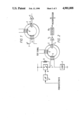
- a known form of detection means for detecting the current I comprises a core 2 of magnetisable material in the shape of a toroid and defining a magnetic circuit, the conductor 1 being wound as a winding 3 on the core 2, there being in a gap in the latter a linear output Hall effect transducer 4 whose output is coupled to an amplifier 5.
- Current I produces a flux in the magnetic circuit formed by the core 2, the magnitude of which is proportional to the magnitude of the current I
- the transducer 4 produces an electrical signal proportional to the magnitude of flux passing through it, which signal is thus proportional to the current I.
- the amplifier 5 then increases the amplitude of this signal to produce an indication of the magnitude of the current I.
- the winding 3 may be short-circuited, thus giving a zero measurement when a current is actually flowing.
- the winding 3 may develop a shorted turn, resulting in less flux being produced and thus giving a measurement of less current than is actually flowing
- the core 2 may fracture, increasing the reluctance and decreasing the flux. This would result in a measurement of less current than is actually flowing.
- the transducer 4 may move out of the gap and consequently out of the flux path. This would result in a measurement of less current than is actually flowing.
- the characteristics of the transducer 4 may change and result in an increased or decreased measurement.
- the gain of the amplifier 5 may alter and result in an increased or decreased measurement.
- At least some of the above shortcomings may be overcome by adding a further winding 6 on to the core 2, the winding 6 carrying a "test" current for testing the circuit arrangement comprising conductor 1, winding 3, core 2, transducer 4 and amplifier 5--it will be known if there is a fault in this circuit arrangement if the output of amplifier 5 is not what would be expected from the test current.
- FIG. 2 is a diagram of an embodiment using such a further winding, items in FIG. 2 which correspond with items in FIG. 1 having been given the same reference numerals as in FIG. 1.
- direct current I in conductor 1 is passed through a load 7 by closing a switch 8 under the control of a microprocessor 9, the switch 8, the winding 3 and the load 7 being connected in series across a voltage supply.
- the output of the amplifier 5 is connected to a detector 10 whose output is connected to the microprocessor 9.
- a low resistance proof resistor 11 is connected across the switch 8.
- a direct test current of known magnitude is passed through the winding 6, so that the output signal of the detector 10 will be of a known, expected magnitude if there is no fault as regards the core 2, the transducer 4, the amplifier 5 and the detector 10, but not of this magnitude if there is such a fault.
- the circuit arrangement of FIG. 2 guards against the above shortcomings in the following manner:
- the microprocessor 9 expects an output signal from the detector 10 that corresponds to the state of the switch 8. If there is a zero output even though switch 8 is closed, then the microprocessor detects that there is a fault.
- core fracture can be detected by virtue of a lower output signal from the detector 10 than expected as a result of the test current and this can be detected by the microprocessor 9.
- the microprocessor 9 if there is a positional fault in the transducer 4, a change in the latter's characteristics, a change in the characteristics of the amplifier 5 or a fault in the detector 10, the output signal from the latter resulting from the test current will not be as expected and this can be detected by the microprocessor 9.
- this is a diagram of an arrangement for controlling the energisation of a load which is the filament of a lamp, which could, for example, be a railway signalling lamp.
- a load which is the filament of a lamp
- a railway signalling lamp In a railway signalling environment, it is, of course, essential that the filament of a signalling lamp only be energised when it should be and it must also be known if the filament is not being energised to the correct amount when it should be.
- items which are the same as items in FIG. 2 have been given the same reference numerals as in FIG. 2.
- the arrangement of FIG. 3 allows for the measurement of the current flowing in the filament and also allows for the testing of the measurement function without affecting the filament current magnitude.
- the filament of the lamp (11) is connected in series with a pair of switches SW1 and SW2 and a fuse 12 across a voltage supply. Connected in parallel across switch SW1 is a low resistance proof resistor 13 and connected in parallel across switch SW2 is a low resistance proof resistor 14.
- the opening and closing of switches SW1 and SW2 is effected under the control of the microprocessor 9 via respective enabling circuits 15 and 16.
- Each of circuits 15 and 16 comprises an opto-isolator and an AND gate.
- the microprocessor 9 carries out self-checking routines and if it is deemed to be operating correctly, then a dynamic signal 17 occurs on a line 18 as a "health signal".
- the signal 17 is passed through a band-pass filter 19 (designed to fail to safety, i.e.
- the function of the detector 10 in FIG. 2 is achieved by a sample and hold circuit 20 whose output feeds an analogue to digital converter 21, the output of the latter being connected to the microprocessor 9. If each of switches SW1 and SW2 is open, then a low current flows through the winding 3 and the filament of the lamp 11, but not enough to cause illumination of the latter, by virtue of resistors 13 and 14.
- the additional winding 6 is provided, functioning as in FIG. 2 by receiving an appropriate direct test current (supplied via supply means 22).
- microprocessor 9 receives an output signal from the converter 21 which indicates that there is a fault condition somewhere in the overall arrangement, then a direct current output is provided on a line 23 to an opto-isolator circuit 24 which provides an output to close a switch SW3, as a result of which a short-circuit is placed across the voltage supply and the fuse 12 is blown to isolate the filament of lamp 11 for safety purposes
- FIG. 4 there will now be described an alternative to the arrangement shown in FIG. 3 whereby tests may be carried out to establish whether: means for detection of the current flowing when the filament of the lamp 11 is to be energised (the "hot filament” current) is operating correctly; whether means for detection of the existence of a fleeting or intermittent current when there should not be a current through the filament is operating correctly; and whether means for detection of the low current through the filament when each of the switches SW1 and SW2 is open (the "cold filament” current) is operating correctly.
- the arrangement of FIG. 3 is altered as shown in FIG. 4. More particularly, the circuit 20 and detector 21 are replaced by three detectors 25, 26 and 27 (which could be Schmitt trigger operational-amplifiers).
- the detector 25 is adapted to trigger if the output of amplifier 5 is indicative of a "hot filament” current; the detector 26 is adapted to trigger if the output of amplifier 5 is indicative of a "cold filament” current; and the detector 27 is adapted to trigger if the output of the amplifier 5 is indicative of a fleeting or intermittent current.
- Reference numerals 28 and 29 denote low resistance proof resistors. As regards the detector 25, this is set to trigger if the current through the filament of lamp 11 is above a threshold slightly less than the "hot filament" current.
- the switch SW4 is closed to allow current to flow through the winding 6a, which is wound so that it produces a flux that opposes that created by the filament current This reduces the flux in the transducer 4 and causes the detector 25 to change state. If it does not change state, then it is known that it is faulty It is to be noted that the lamp brightness will not diminish during this test since the test current through the winding 6a is a direct current.
- the switch SW5 is closed to allow current to flow in the winding 6b. This current is set to a level which produces enough flux to cause the detector 27 to be triggered. If it does not trigger in this event, then it is known that it is faulty. During the testing of the detector 27, the filament of the lamp 11 should not be receiving any current.
Landscapes
- Physics & Mathematics (AREA)
- General Physics & Mathematics (AREA)
- Testing Of Short-Circuits, Discontinuities, Leakage, Or Incorrect Line Connections (AREA)
Abstract
Description
Claims (5)
Applications Claiming Priority (2)
| Application Number | Priority Date | Filing Date | Title |
|---|---|---|---|
| GB8724087 | 1987-10-14 | ||
| GB878724087A GB8724087D0 (en) | 1987-10-14 | 1987-10-14 | Testing circuit arrangement |
Publications (1)
| Publication Number | Publication Date |
|---|---|
| US4901008A true US4901008A (en) | 1990-02-13 |
Family
ID=10625304
Family Applications (1)
| Application Number | Title | Priority Date | Filing Date |
|---|---|---|---|
| US07/252,246 Expired - Lifetime US4901008A (en) | 1987-10-14 | 1988-09-29 | Circuit arrangement for testing the correct functioning of circuit(s) |
Country Status (3)
| Country | Link |
|---|---|
| US (1) | US4901008A (en) |
| CA (1) | CA1286362C (en) |
| GB (1) | GB8724087D0 (en) |
Cited By (26)
| Publication number | Priority date | Publication date | Assignee | Title |
|---|---|---|---|---|
| DE4028089A1 (en) * | 1990-09-05 | 1992-03-12 | Papst Motoren Gmbh & Co Kg | Circuitry detecting constant or alternating magnetic fields - using Hall generators with pulsed supply fed to Hall generators via electronically controlled switches |
| EP0475880A3 (en) * | 1990-09-14 | 1992-07-01 | United Technologies Automotive, Inc. | Magnetic automotive lamp current sensor |
| EP0464748A3 (en) * | 1990-07-02 | 1993-03-24 | Nippondenso Co., Ltd. | Battery condition detecting apparatus and charge control apparatus for automobile |
| US5218298A (en) * | 1992-03-02 | 1993-06-08 | Allegro Microsystems Inc. | Two-terminal-hall-sensors monitoring system for providing decoded magnetic field amplitude signals and system diagnostic signals |
| WO1993026089A1 (en) * | 1992-06-10 | 1993-12-23 | Digital Equipment Corporation | Isolated error-amplifying control circuitry |
| US5280231A (en) * | 1990-07-02 | 1994-01-18 | Nippondenso Co., Ltd. | Battery condition detecting apparatus and charge control apparatus for automobile |
| US5477135A (en) * | 1993-07-15 | 1995-12-19 | Tektronix, Inc. | Current probe |
| ES2103173A1 (en) * | 1994-03-29 | 1997-08-16 | Infrarrojo Y Microelectronica | Self-calibrated digital current sensor. |
| US5701073A (en) * | 1996-02-28 | 1997-12-23 | Tektronix, Inc. | Direct current measuring apparatus and method employing flux diversion |
| EP0933640A2 (en) * | 1998-01-28 | 1999-08-04 | Liaisons Electroniques-Mecaniques Lem S.A. | Power supply comprising a current sensor |
| US6137284A (en) * | 1998-06-11 | 2000-10-24 | Yazaki Corporation | Method and apparatus for detecting supply voltage |
| US6429639B1 (en) * | 1997-01-21 | 2002-08-06 | International Rectifier Corporation | Combined filter inductor and hall current sensor |
| US6484974B1 (en) | 2001-09-10 | 2002-11-26 | Union Switch & Signal, Inc. | Controller for switch machine |
| US6494409B1 (en) * | 2002-02-06 | 2002-12-17 | Union Switch & Signal, Inc. | Railway code following apparatus |
| US6515468B1 (en) * | 1999-08-27 | 2003-02-04 | Yazaki Corporation | Current sensor and electric circuit using the same |
| US6570373B1 (en) * | 2002-03-07 | 2003-05-27 | Visteon Global Technologies, Inc. | Current sensor programmable through connector |
| WO2006056510A1 (en) * | 2004-11-24 | 2006-06-01 | Siemens Aktiengesellschaft | Circuit for controlling and monitoring a plurality of signal lamps |
| US20060176047A1 (en) * | 2003-02-27 | 2006-08-10 | Gerard Lepine | Electric current sensor |
| US20080143329A1 (en) * | 2006-12-14 | 2008-06-19 | Denso Corporation | Semiconductor integrated circuit for detecting magnetic field |
| WO2008058981A3 (en) * | 2006-11-15 | 2008-07-10 | Continental Automotive Gmbh | Arrangement and method for determining load currents in a vehicle |
| US20100097049A1 (en) * | 2007-03-02 | 2010-04-22 | Liaisons Electroniques-Mecaniques Lem S.A. | High Bandwidth Open-Loop Current Sensor |
| US20100164501A1 (en) * | 2006-09-13 | 2010-07-01 | Mtu Aero Engines Gmbh | Alternating current switch device and method for the monitoring or diagnosis of the operability of an alternating current switch device |
| WO2015070927A1 (en) * | 2013-11-18 | 2015-05-21 | Enel Distribuzione S.P.A. | Electricity meter with fault detection mechanism and fault detection method |
| US20150301148A1 (en) * | 2011-12-14 | 2015-10-22 | Robert Bosch Gmbh | Method for Checking an Electrical Current Measurement, Circuit for Carrying Out the Method, Battery and Motor Vehicle |
| SE1951382A1 (en) * | 2019-12-03 | 2021-06-04 | Bombardier Transp Gmbh | Remote sensor arrangement |
| CN118191704A (en) * | 2023-12-27 | 2024-06-14 | 西安亚能电气有限责任公司 | Self-checking device and method for lightning arrester leakage current monitoring device |
Citations (3)
| Publication number | Priority date | Publication date | Assignee | Title |
|---|---|---|---|---|
| US3518459A (en) * | 1967-06-28 | 1970-06-30 | Burroughs Corp | Negative resistance magnetoresistive device |
| US4692703A (en) * | 1984-02-25 | 1987-09-08 | Standard Telephones And Cables Public Limited Company | Magnetic field sensor having a Hall effect device with overlapping flux concentrators |
| US4742296A (en) * | 1986-02-10 | 1988-05-03 | Lgz Landis & Gyr Zug Ag | Arrangement for measuring electrical power |
-
1987
- 1987-10-14 GB GB878724087A patent/GB8724087D0/en active Pending
-
1988
- 1988-08-03 CA CA000573732A patent/CA1286362C/en not_active Expired - Lifetime
- 1988-09-29 US US07/252,246 patent/US4901008A/en not_active Expired - Lifetime
Patent Citations (3)
| Publication number | Priority date | Publication date | Assignee | Title |
|---|---|---|---|---|
| US3518459A (en) * | 1967-06-28 | 1970-06-30 | Burroughs Corp | Negative resistance magnetoresistive device |
| US4692703A (en) * | 1984-02-25 | 1987-09-08 | Standard Telephones And Cables Public Limited Company | Magnetic field sensor having a Hall effect device with overlapping flux concentrators |
| US4742296A (en) * | 1986-02-10 | 1988-05-03 | Lgz Landis & Gyr Zug Ag | Arrangement for measuring electrical power |
Non-Patent Citations (2)
| Title |
|---|
| Kulesho; "Measuring Low Voltage in a D.C. Circuit"; Instruments and Experimental Techniques; vol. 19, No. 2, Pt. 2, pp. 562-563; Mar.-Apr. 1976. |
| Kulesho; Measuring Low Voltage in a D.C. Circuit ; Instruments and Experimental Techniques; vol. 19, No. 2, Pt. 2, pp. 562 563; Mar. Apr. 1976. * |
Cited By (36)
| Publication number | Priority date | Publication date | Assignee | Title |
|---|---|---|---|---|
| EP0464748A3 (en) * | 1990-07-02 | 1993-03-24 | Nippondenso Co., Ltd. | Battery condition detecting apparatus and charge control apparatus for automobile |
| US5280231A (en) * | 1990-07-02 | 1994-01-18 | Nippondenso Co., Ltd. | Battery condition detecting apparatus and charge control apparatus for automobile |
| US5412323A (en) * | 1990-07-02 | 1995-05-02 | Nippondenso Co., Ltd. | Battery condition detecting apparatus and charge control apparatus for automobile |
| DE4028089A1 (en) * | 1990-09-05 | 1992-03-12 | Papst Motoren Gmbh & Co Kg | Circuitry detecting constant or alternating magnetic fields - using Hall generators with pulsed supply fed to Hall generators via electronically controlled switches |
| DE4028089B4 (en) * | 1990-09-05 | 2005-06-09 | Papst Licensing Gmbh & Co. Kg | Circuit arrangement for detecting constant or alternating magnetic fields |
| EP0475880A3 (en) * | 1990-09-14 | 1992-07-01 | United Technologies Automotive, Inc. | Magnetic automotive lamp current sensor |
| US5218298A (en) * | 1992-03-02 | 1993-06-08 | Allegro Microsystems Inc. | Two-terminal-hall-sensors monitoring system for providing decoded magnetic field amplitude signals and system diagnostic signals |
| WO1993026089A1 (en) * | 1992-06-10 | 1993-12-23 | Digital Equipment Corporation | Isolated error-amplifying control circuitry |
| US5493211A (en) * | 1993-07-15 | 1996-02-20 | Tektronix, Inc. | Current probe |
| US5477135A (en) * | 1993-07-15 | 1995-12-19 | Tektronix, Inc. | Current probe |
| ES2103173A1 (en) * | 1994-03-29 | 1997-08-16 | Infrarrojo Y Microelectronica | Self-calibrated digital current sensor. |
| US5701073A (en) * | 1996-02-28 | 1997-12-23 | Tektronix, Inc. | Direct current measuring apparatus and method employing flux diversion |
| US6429639B1 (en) * | 1997-01-21 | 2002-08-06 | International Rectifier Corporation | Combined filter inductor and hall current sensor |
| EP0933640A2 (en) * | 1998-01-28 | 1999-08-04 | Liaisons Electroniques-Mecaniques Lem S.A. | Power supply comprising a current sensor |
| US6137284A (en) * | 1998-06-11 | 2000-10-24 | Yazaki Corporation | Method and apparatus for detecting supply voltage |
| US6515468B1 (en) * | 1999-08-27 | 2003-02-04 | Yazaki Corporation | Current sensor and electric circuit using the same |
| US6484974B1 (en) | 2001-09-10 | 2002-11-26 | Union Switch & Signal, Inc. | Controller for switch machine |
| US6494409B1 (en) * | 2002-02-06 | 2002-12-17 | Union Switch & Signal, Inc. | Railway code following apparatus |
| US6717396B2 (en) | 2002-03-07 | 2004-04-06 | Visteon Global Technologies, Inc. | Housing with retainer tab for positioning a current sensor magnetic field concentrating core |
| US6570373B1 (en) * | 2002-03-07 | 2003-05-27 | Visteon Global Technologies, Inc. | Current sensor programmable through connector |
| US20060176047A1 (en) * | 2003-02-27 | 2006-08-10 | Gerard Lepine | Electric current sensor |
| US7492145B2 (en) * | 2003-02-27 | 2009-02-17 | Liaisons Electroniques-Mecaniques Lem S.A. | Electric current sensor with a bracket attached to the core on either side of the air-gap and outside of the air gap |
| WO2006056510A1 (en) * | 2004-11-24 | 2006-06-01 | Siemens Aktiengesellschaft | Circuit for controlling and monitoring a plurality of signal lamps |
| US20100164501A1 (en) * | 2006-09-13 | 2010-07-01 | Mtu Aero Engines Gmbh | Alternating current switch device and method for the monitoring or diagnosis of the operability of an alternating current switch device |
| WO2008058981A3 (en) * | 2006-11-15 | 2008-07-10 | Continental Automotive Gmbh | Arrangement and method for determining load currents in a vehicle |
| US20080143329A1 (en) * | 2006-12-14 | 2008-06-19 | Denso Corporation | Semiconductor integrated circuit for detecting magnetic field |
| US7977934B2 (en) * | 2007-03-02 | 2011-07-12 | Liaisons Electroniques-Mechaniques Lem S.A. | High bandwidth open-loop current sensor |
| US20100097049A1 (en) * | 2007-03-02 | 2010-04-22 | Liaisons Electroniques-Mecaniques Lem S.A. | High Bandwidth Open-Loop Current Sensor |
| US20150301148A1 (en) * | 2011-12-14 | 2015-10-22 | Robert Bosch Gmbh | Method for Checking an Electrical Current Measurement, Circuit for Carrying Out the Method, Battery and Motor Vehicle |
| WO2015070927A1 (en) * | 2013-11-18 | 2015-05-21 | Enel Distribuzione S.P.A. | Electricity meter with fault detection mechanism and fault detection method |
| CN106164695A (en) * | 2013-11-18 | 2016-11-23 | 埃内尔迪斯特里布齐恩公司 | There is kilowatt meter and the fault detection method of fault detection mechanism |
| US10048308B2 (en) | 2013-11-18 | 2018-08-14 | Enel Distribuzione S.P.A. | Electricity meter with fault detection mechanism and fault detection method |
| CN106164695B (en) * | 2013-11-18 | 2019-03-19 | 埃内尔迪斯特里布齐恩公司 | Electric power meter with fault detection mechanism and fault detection method |
| SE1951382A1 (en) * | 2019-12-03 | 2021-06-04 | Bombardier Transp Gmbh | Remote sensor arrangement |
| US11372028B2 (en) | 2019-12-03 | 2022-06-28 | Bombardier Transportation Gmbh | Remote sensor arrangement |
| CN118191704A (en) * | 2023-12-27 | 2024-06-14 | 西安亚能电气有限责任公司 | Self-checking device and method for lightning arrester leakage current monitoring device |
Also Published As
| Publication number | Publication date |
|---|---|
| GB8724087D0 (en) | 1987-11-18 |
| CA1286362C (en) | 1991-07-16 |
Similar Documents
| Publication | Publication Date | Title |
|---|---|---|
| US4901008A (en) | Circuit arrangement for testing the correct functioning of circuit(s) | |
| US6484974B1 (en) | Controller for switch machine | |
| US5365223A (en) | Fail-safe condition sensing circuit | |
| US5243291A (en) | Electromagnetic contactor deposition detecting apparatus which detects load current and switch current | |
| AU2002336464A1 (en) | Controller for switch machine | |
| US3995262A (en) | Electric lamp failure indicator circuit | |
| CA1193664A (en) | Hall effect device test circuit | |
| US3978400A (en) | Ground fault detector with a nonlinear sensing means | |
| SK280364B6 (en) | Circuit configuration for actuating a safety relay | |
| US4488112A (en) | Hall effect device test circuit | |
| US5610532A (en) | Isolated DC fault current sensor | |
| CA1193666A (en) | Current sensing relay | |
| US4023153A (en) | Device for indicating any wire breaking in parallel connected plural loads | |
| EP0221775A1 (en) | Testable voted logic power circuit and method of testing the same | |
| CA1038484A (en) | Track circuit | |
| US4668946A (en) | System for detecting the failure of a filament lamp | |
| GB2244397A (en) | Residual current protective device | |
| US4451018A (en) | Non contact isolated current detector | |
| CA1186789A (en) | Axle sensor for rail vehicle | |
| US4318093A (en) | Logic circuit monitor | |
| US3919703A (en) | Fault detection system for transducers | |
| AU623061B2 (en) | Voltage detection | |
| JPH04242174A (en) | Trouble discriminator for detector | |
| US6563326B1 (en) | Bus-driveable sensor apparatus with direction-dependent current/voltage characteristic curve and method for testing the apparatus | |
| DE4215184C2 (en) | Methods and devices for the detection of residual currents |
Legal Events
| Date | Code | Title | Description |
|---|---|---|---|
| AS | Assignment |
Owner name: WESTINGHOUSE BRAKE AND SIGNAL COMPANY LIMITED, PEW Free format text: ASSIGNMENT OF ASSIGNORS INTEREST.;ASSIGNORS:QUASTEL, DAVID A.;HILL, NIGEL K.;REEL/FRAME:004951/0206 Effective date: 19880707 Owner name: WESTINGHOUSE BRAKE AND SIGNAL COMPANY LIMITED, PEW Free format text: ASSIGNMENT OF ASSIGNORS INTEREST;ASSIGNORS:QUASTEL, DAVID A.;HILL, NIGEL K.;REEL/FRAME:004951/0206 Effective date: 19880707 |
|
| STCF | Information on status: patent grant |
Free format text: PATENTED CASE |
|
| FEPP | Fee payment procedure |
Free format text: PAYOR NUMBER ASSIGNED (ORIGINAL EVENT CODE: ASPN); ENTITY STATUS OF PATENT OWNER: LARGE ENTITY |
|
| FPAY | Fee payment |
Year of fee payment: 4 |
|
| FPAY | Fee payment |
Year of fee payment: 8 |
|
| FPAY | Fee payment |
Year of fee payment: 12 |
|
| AS | Assignment |
Owner name: DEUTSCHE BANK AG, LONDON, UNITED KINGDOM Free format text: SECURITY INTEREST;ASSIGNOR:WESTINGHOUSE BRAKE AND SIGNAL HOLDINGS LIMITED;REEL/FRAME:015177/0458 Effective date: 20040401 |
|
| AS | Assignment |
Owner name: DEUTSCHE BANK AG, LONDON BRANCH, UNITED KINGDOM Free format text: SECURITY AGREEMENT;ASSIGNOR:WESTINGHOUSE BRAKE AND SIGNAL HOLDINGS LIMITED;REEL/FRAME:017921/0911 Effective date: 20060713 |
|
| AS | Assignment |
Owner name: WESTINGHOUSE BRAKE AND SIGNAL HOLDINGS LTD, UNITED Free format text: RELEASE AND TERMINATION OF SECURITY INTEREST;ASSIGNOR:DEUTSCHE BANK AG, LONDON BRANCH;REEL/FRAME:018039/0075 Effective date: 20060713 |