US4900941A - Method and apparatus for verifying indicia correctly provided on an object - Google Patents
Method and apparatus for verifying indicia correctly provided on an object Download PDFInfo
- Publication number
- US4900941A US4900941A US07/098,581 US9858187A US4900941A US 4900941 A US4900941 A US 4900941A US 9858187 A US9858187 A US 9858187A US 4900941 A US4900941 A US 4900941A
- Authority
- US
- United States
- Prior art keywords
- indicia
- detecting
- count
- zone
- determining
- Prior art date
- Legal status (The legal status is an assumption and is not a legal conclusion. Google has not performed a legal analysis and makes no representation as to the accuracy of the status listed.)
- Expired - Lifetime
Links
Images

Classifications
-
- G—PHYSICS
- G06—COMPUTING; CALCULATING OR COUNTING
- G06K—GRAPHICAL DATA READING; PRESENTATION OF DATA; RECORD CARRIERS; HANDLING RECORD CARRIERS
- G06K7/00—Methods or arrangements for sensing record carriers, e.g. for reading patterns
- G06K7/10—Methods or arrangements for sensing record carriers, e.g. for reading patterns by electromagnetic radiation, e.g. optical sensing; by corpuscular radiation
- G06K7/10544—Methods or arrangements for sensing record carriers, e.g. for reading patterns by electromagnetic radiation, e.g. optical sensing; by corpuscular radiation by scanning of the records by radiation in the optical part of the electromagnetic spectrum
- G06K7/10821—Methods or arrangements for sensing record carriers, e.g. for reading patterns by electromagnetic radiation, e.g. optical sensing; by corpuscular radiation by scanning of the records by radiation in the optical part of the electromagnetic spectrum further details of bar or optical code scanning devices
- G06K7/10861—Methods or arrangements for sensing record carriers, e.g. for reading patterns by electromagnetic radiation, e.g. optical sensing; by corpuscular radiation by scanning of the records by radiation in the optical part of the electromagnetic spectrum further details of bar or optical code scanning devices sensing of data fields affixed to objects or articles, e.g. coded labels
-
- B—PERFORMING OPERATIONS; TRANSPORTING
- B07—SEPARATING SOLIDS FROM SOLIDS; SORTING
- B07C—POSTAL SORTING; SORTING INDIVIDUAL ARTICLES, OR BULK MATERIAL FIT TO BE SORTED PIECE-MEAL, e.g. BY PICKING
- B07C3/00—Sorting according to destination
- B07C3/10—Apparatus characterised by the means used for detection ofthe destination
- B07C3/14—Apparatus characterised by the means used for detection ofthe destination using light-responsive detecting means
Definitions
- This invention relates to a method and apparatus for sensing indicia on an object and, more particularly, to sensing if indicia are present or absent at selected locations, or zones, on the object.
- indicia are printed or otherwise provided on objects which subsequently are handled for various purposes.
- pre-addressed envelopes may be conveyed and passed rapidly through a printer which operates to print various additional indicia on those envelopes.
- bar codes representing zip codes may be printed on the envelopes; these bar codes being sensed by postal service equipment for the rapid classification of mail by zip code destination.
- Other indicia also may be printed on the envelopes for the purpose of providing sorting of mailing pieces, postage discounts and record keeping, all associated with rapid processing of large volumes of mail.
- indicia are printed at various select locations on the envelope by high-speed mail-handling equipment. To assure the correct operation of such equipment, it is important to verify that indicia are, in fact, printed at those selected locations. Indeed, it may be as important to verify the presence of indicia as to interpret that indicia.
- indicia verifying equipment of the aforementioned type should be adaptable to accommodate envelopes of various sizes and shapes, and should be further adaptable for use with different sets of envelopes wherein one set may be provided with indicia at one location thereon while, in another set, that same location may be provided with no indicia.
- Postal Service with a manifest of mail pieces (e.g. envelopes) which summarizes the number of pieces directed to specific zip code destinations, and to bundle such pieces to facilitate further processing by the Postal Service.
- informational indicia and, in many instances, coded indicia are provided on each envelope.
- coded indicia such as bar codes
- the Postal Service grants discounts in the established postage rates to those who comply with the particular regulations associated with this discounted service.
- users may forfeit the discounts to which they otherwise might be entitled, and may even be subject to various monetary penalties.
- Another object of this invention is to verify the presence of indicia at correct locations on an object.
- a further object of this invention is to provide a system that is adaptable for use with objects (for example, envelopes) of differing sizes and shapes on which indicia may or may not be printed at different locations or zones.
- objects for example, envelopes
- An additional object of this invention is to provide a method and apparatus for "learning” the locations of particular zones on a sample of an object and also “learning” whether indicia are provided at the respective zones; and then verifying the presence of such indicia at the proper zones on actual (or working) objects.
- Yet another object of this invention is to provide a system of the aforementioned type which additionally detects whether adjacent objects (such as envelopes or documents) overlap.
- the presence of indicia correctly provided on an object is verified by providing relative movement between the object and a sensor, determining the location on the object at which indicia are expected and then sensing whether indicia are present at that location.
- the leading edge of the object is detected, and one or more locations at which indicia are expected are measured from that leading edge.
- pulses are generated as relative movement between the object and the sensor is provided, these pulses are counted and particular locations, or zones, are represented by respective pulse counts.
- indicia are not expected in a particular zone, but indicia are PG,6 sensed, an error indication is provided.
- an error indication is produced.
- indicia are sensed by optically scanning the object.
- a signal is produced whose level changes as a function of the light intensity sensed by the optical sensor.
- the presence of indicia is determined by detecting whether the average signal level changes over a period of time exceed a threshold level.
- the leading and trailing edges of the object are detected, and the number of pulses generated between the leading and trailing edges are compared to an approximate pulse count which represents the length of the object. If the trailing edge has not been detected by the time the actual pulse count exceeds the approximate pulse count, an error indication is provided, representing the likelihood that successive objects overlap.
- this invention may be used to verify the presence of indicia at different zones on objects of various sizes and shapes. For example, indicia at different zones on envelopes of different sizes may be verified.
- the system which is used to carry out the present invention may be operated initially in a "learning" mode to scan a relatively small number of samples on which indicia are provided. During the "learning" mode, the locations of such indicia are sensed to establish zones in which indicia are expected. Based upon the "learning" mode, or set-up procedure, the system subsequently is operated in its "verifying" mode to sense whether indicia are provided on objects in the proper zones. If indicia are sensed outside these zones; or if indicia are not sensed in the "learned” zones, error indications are provided. During the "learning” mode, the actual length of the object also is determined.
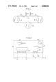
- FIG. 1 is a schematic representation of a system which includes the present invention
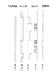
- FIG. 2 is an illustration of indicia which are verified by the present invention as being provided at respective locations, or zones, of an envelope;
- FIGS. 3A-3E are timing diagrams and waveforms which are useful in understanding the present invention.
- FIG. 4 is a flow chart representing the manner in which the present invention operates to verify indicia that are correctly provided on a proper object
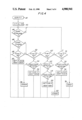
- FIG. 5 is a flow chart illustrating the manner in which the present invention "learns" where to expect indicia on an object that is verified by this invention.
- FIG. 1 is a schematic representation of apparatus with which the present invention finds ready application.
- the present invention will be described in the environment of mail-handling equipment.
- the present invention is used to verify printed indicia provided on particular locations, or zones, of envelopes.
- this invention can be used to verify indicia provided at proper locations on other objects, such as documents (e.g. forms which are generated by other apparatus or forms which are pre-printed and to which additional information is added), containers (e.g. beverage cans that are marked with particular codes to identify the product, date of manufacture, date of processing, place of manufacture, destination, etc.), machine parts, assembly components, baggage, and virtually any other object on which indicia may be provided at selected locations.
- documents e.g. forms which are generated by other apparatus or forms which are pre-printed and to which additional information is added
- containers e.g. beverage cans that are marked with particular codes to identify the product, date of manufacture, date of processing, place of manufacture, destination, etc.
- machine parts e.g. beverage
- the apparatus illustrated in FIG. 1 is adapted to transport a series of envelopes, such as envelopes 10, 12, etc., past a sensing station whereat indicia provided at proper locations on each envelope are verified.
- the envelopes are supplied from further apparatus (not shown) located upstream of the equipment illustrated in FIG. 1; and when supplied, envelopes 10 and 12 are transported by means of a transport mechanism 14, such as an endless conveyor belt or other conventional conveying apparatus.
- endless belt 14 is deployed about drive wheels 16 and 18 which are driven by suitable means (not shown) to advance the endless belt in the direction illustrated by the arrow.
- suitable hold-down means (not shown) retains envelopes 10 and 12 on belt 14 such that these envelopes move as the belt is driven by drive wheels 16 and 18.
- An encoder 20 is mechanically coupled to the illustrated transport mechanism and is adapted to generate a series of pulses as the endless belt is driven.
- a suitable encoder wheel also known as a chopper wheel, or other conventional apparatus may be used to generate these pulses by modulating a suitable sensor (not shown). It is appreciated that the pulses generated by encoder 20 exhibit a timed relationship as the endless belt (and, thus, as each envelope) moves. Hence, a count of these pulses may be used as a measure of the distance a particular envelope moves past a sensor.
- Envelopes 10 and 12 are transported by transport mechanism 14 past one or more fixed sensors 22 and 24.
- sensors 22 and 24 are formed as optical sensors for the purpose of sensing the presence of an envelope transported thereto and also to sense the presence or absence of indicia printed on the envelope.
- FIG. 1 two optical sensing devices are shown, wherein photo sensor 22 operates to detect the leading edge of an envelope (and, if desired, the trailing edge) and photoelectric detector 24, spaced from photo sensor 22 by a fixed, known distance, senses the presence (or absence) of indicia on an envelope transported therebeneath.
- Photoelectric detector 24 is provided with suitable electronics to produce a signal whose level changes as a function of the light intensity reflected to and picked up by the detector.
- photoelectric detector 24 may be formed as a C40000 Series Square Skamps scanner/amplifier, manufactured by Skan-A-Matic Corporation. Of course, other suitable photoelectric detectors may be used in place of the Skan-A-Matic device.
- Photoelectric detector 24 may be adapted to scan the equivalent of a single line of printed indicia on an envelope or, alternatively, the detecting fluid of the photoelectric detector may be large enough to sense printed indicia disposed in two lines.
- the photoelectric detector may be capable of scanning in the vertical direction, relative to the horizontal passage of an envelope therebeneath, to detect the presence of printed indicia in two separate lines. Still further, two or more photoelectric detectors may be provided, one for each expected horizontal line of print indicia.
- two separate optical detecting devices 22 and 24 are provided, one to detect the presence and, additionally, the leading edge (and, if desired, the trailing edge) of an envelope, and the other to detect the presence of indicia on the envelope. If desired, these different functions may be carried out by a single optical detecting device, such as photoelectric detector 24.
- the embodiment shown in FIG. 1 contemplates the transport of envelopes 10 and 12 past one or more fixed optical detecting devices
- the present invention may be used by moving the optical detecting device(s) past fixed envelopes.
- individual pieces of mail i.e. envelopes
- the expression "relative movement” is intended to mean either movement of the envelopes past fixed optical detecting devices or movement of optical detecting devices past fixed envelopes.
- sensing devices other than an optical detector may be used to sense the presence and/or leading and/or trailing edge of an envelope.
- a mechanical element such as a wiper
- Other devices such as those which detect a change in electrical properties (e.g. capacitance) due to the presence of a paper envelope, also may be used.
- Envelope 10 is provided with a leading edge 30 and a trailing edge 32.
- Zone B Located in the vicinity of the lower longitudinal edge of the envelope are particular zones which, for convenience, are identified as follows: Zone B, referred to commonly as a "reserved space” in which indicia 26 may or may not be provided; Zone C, commonly referred to as an "endorsement space” in which indicia 28 may or may not be provided; and Zone D, commonly referred to as a "trailing space” in which indicia normally are not provided.
- Zone B referred to commonly as a "reserved space” in which indicia 26 may or may not be provided
- Zone C commonly referred to as an "endorsement space” in which indicia 28 may or may not be provided
- Zone D commonly referred to as a "trailing space” in which indicia normally are not provided.
- the space which normally separates successive envelopes 10 and 12 (FIG.
- Zone A is identified as Zone A, referred to merely as "between envelopes" space.
- the photoelectric detector senses Zone A, followed by leading edge 30, followed by Zone B, followed by Zone C, followed by Zone D, followed by trailing edge 32, followed by Zone A, and so on.
- indicia 26 are comprised of conventional bar codes which, for example, may identify the zip code destination to which envelope 10 is to be mailed. Of course, other information may be used as indicia 26, including human-readable data. It is expected that, in a "batch" of envelopes processed during one run with the present invention, all of the envelopes included in that batch will be of the same size and shape; indicia 26 will be of uniform length, and it is expected that the indicia will be provided in substantially the same location in Zone B for all of the envelopes in this batch.
- each envelope in that batch may differ from the envelopes included in a preceding batch, indicia 26 may be omitted in that subsequent batch, or the length of the indicia may vary from that of the preceding batch, and the particular location of indicia 26 in Zone B likewise may vary. This will be described in greater detail below.
- Indicia 28 may be comprised of alphanumeric information, such as mail sort categories which are used in conjunction with postage discounts provided by the Postal Service, or other information that, typically, is printed on envelopes mailed by high volume users. Indicia 28 may be disposed along a single horizontal line or, alternatively, may be present in two (or even more) lines. In one batch of envelopes, indicia 28 generally are provided at the same location within Zone C for all envelopes. In one embodiment, the beginning of indicia 28 corresponds with the beginning of Zone C and the end of indicia 28 corresponds with the end of Zone C. Alternatively, the indicia may be disposed within and spaced from the beginning and ending boundaries of Zone C. Indicia 28 normally are provided on envelope 10, although the present invention may be used in applications wherein Zone C is expected to be free of indicia.
- the present invention also may be used to detect the presence of indicia positioned at any other location on envelope 10, for example, to verify the existence of metered indicia 34, a brief description of the manner in which indicia 26 and 28 are verified as being located in Zones B and C now is provided.
- photo sensor 22 is used merely to sense the presence of an envelope. If an envelope is not sensed by the photo sensor, an error indication is provided and, if desired, the mail-handling equipment may be halted. It is further assumed that photoelectric detector 24 detects leading edge 30, indicia 26, indicia 28 and trailing edge 32. Of course, and as mentioned above, the leading and trailing edges of envelope 10 may be sensed by photo sensor 22.
- encoder pulses As envelope 10 is transported, a series of pulses (referred to for convenience as “encoder pulses”) is generated by encoder 20. As a numerical example, the speed and dimensions of the transport mechanism may be such that approximately 62.3 encoder pulses are generated for each inch of movement of an envelope. These encoder pulses are illustrated in FIG. 3A.
- a significant change in light intensity is sensed by photoelectric detector 24, resulting in, for example, a negative-going change in the signal level produced by the photoelectric detector.
- This negative-going change is illustrated in FIG. 3B and represents the end of Zone A (i.e. the space between successive envelopes), and the beginning of Zone B Photoelectric detector 24 senses whether indicia are present in Zone B.
- photoelectric detector 24 Upon sensing the beginning of indicia 26 at location B 1 in Zone B, photoelectric detector 24 produces a positive-going change in the signal level produced thereby at location B 1 , as illustrated in FIG. 3C. It is expected that the signal level produced by the photoelectric detector undergoes a number of level changes corresponding to the changes in light intensity resulting from indicia 26. These signal level changes extend from the beginning of indicia 26, at location B 1 , to the end of the indicia at location B 2 . FIG. 3D is a simplified representation of such signal level changes.
- the signal level changes shown in FIG. 3D may be integrated over a period of time to produce a relatively slowly varying signal, and this slowly varying signal may be compared to a threshold level.
- the integrated signal may be thought of as the time-average of the photoelectric detector signal level changes, and this is illustrated by the waveform of FIG. 3E. If the time-average signal exceeds threshold level L, indicia are verified.
- the transitions at B 1 and B 2 in FIG. 3C, the signal level changes in the interval B 1 -B 2 in FIG. 3D, and the time-average signal in interval B 1 -B 2 in FIG. 3E will not be produced.
- photoelectric detector 24 senses a change in the intensity of light impinging thereon due to the presence of the indicia.
- This level change in light intensity produces a change in the level of the signal produced by the photoelectric detector, as represented by the positive transition at the boundary between Zones B and C in FIG. 3B.
- FIG. 3C also illustrates this positive-going transition at location C 1 .
- indicia 28 produce the changes in signal level illustrated in FIG. 3D. It is appreciated that this change in signal level extends from location C 1 to location C 2 , and in this example the interval C 1 -C 2 corresponds to Zone C.
- the resultant signal exhibits a relatively slowly changing amplitude, as shown in FIG. 3E. This slowly changing amplitude is compared to threshold L to provide an indication of the presence of indicia when the threshold is exceeded.
- the signal produced by photoelectric detector 24 undergoes a negative transition, as represented by the waveforms shown in FIGS. 3B and 3C. Then, upon detecting trailing edge 32, the signal produced by the photoelectric detector undergoes a positive transition which establishes the boundary from Zone D to Zone A. The photoelectric detector now senses the space between successive envelopes; and upon detecting the leading edge of the next-following envelope, the signal produced by the photoelectric detector undergoes the changes represented by the waveforms of FIGS. 3B-3E once again.
- the pulses which are generated as envelope 10 is transported may be counted as the envelope is moved relative to photoelectric detector 24.
- the pulse count which is obtained at the transition from Zone A to Zone B that is, the pulse count which is produced when leading edge 30 is detected, may be stored to establish the beginning of Zone B.
- the pulse count which is obtained at the transition from Zone B to Zone C that is, when indicia 28 are detected, may be stored. The difference between these pulse counts represents the interval of Zone B. If the presence of indicia is not detected during this interval, that is, if the transitions at locations B 1 and B 2 (FIG.
- indicia are not present in Zone B. If indicia are not expected in this zone (as will be described below), then no error indication is provided. However, if it is anticipated that indicia 26 should be present, then the absence of sensing such indicia in Zone B results in an error indication.
- the pulse counts obtained at the beginning and end of Zone C may be stored. If indicia are expected within this zone, an error indication is provided in the event that indicia are not sensed during the interval between these pulse counts. Conversely, if indicia are sensed between the time that the pulse count changes from that corresponding to location C 1 to that corresponding to location C 2 , no error indication is provided. However, if indicia are not expected in the interval between these pulse counts, the presence of indicia will result in an error indication.
- Zone D will be of a predetermined length. It is appreciated that this length is determined as a function of the pulse count which is obtained at the transition between Zone C and Zone D to the pulse count which is obtained when trailing edge 32 is detected. However, if the pulse count continues to increment so as to exceed a predetermined amount prior to the detection of a trailing edge, an error indication may be provided. Such excessive pulse counts may be caused by, for example, an overlap of successive envelopes, thereby impeding the ability of photoelectric detector 24 to detect trailing edge 32. Such an overlap gives rise to a potential jam in the mail-handling equipment; and it is preferred that an error indication thereof be provided to allow corrective action to be taken to avoid such a jam.
- an error indication may be provided if the signal produced by photoelectric detector 24 undergoes level changes attributed to indicia after the pulse count corresponding to the transition from Zone C to Zone D is obtained.
- Zone B may be defined by a predetermined count (referred to as Count B) which is accumulated from the time that leading edge 30 is detected to the time that indicia 28 are detected.
- Zone C may be defined by another count (referred to as Count C) which is accumulated from the time that leading edge 30 is detected to the time that the end of indicia 28 are detected.
- Zone D may be defined by the count which is accumulated (referred to as Count D) from the time that the leading edge is detected to the time that trailing edge 32 is detected.
- the presence of indicia in Zone B is determined by sensing if indicia are present prior to the time that Count B has been accumulated.
- the presence of indicia 28 is determined by sensing if indicia are detected between Counts B and C.
- the presence of indicia in Zone D is determined by sensing indicia between Counts C and D. An overlap is determined if Count D has been reached prior to detecting the presence of trailing edge 32.
- Counts B, C and D may be adjusted accordingly.
- the signals produced by photo sensor 22, photoelectric detector 24 and encoder 20 are supplied to a data processing device, or to a suitably programmed microprocessor, such as an Intel Model 8088, or the like.
- a microprocessor operates to sense whether indicia are provided at proper locations on an envelope 10 now will be described in conjunction with the flow chart illustrated in FIG. 4. For the purpose of the present discussion, it will be assumed that counts corresponding to counts B, C and D have been determined and stored previously, thereby establishing the locations and sizes of Zones B, C and D, respectively.
- the routine illustrated in FIG. 4 is referred to as the verify routine 40; and this routine commences by carrying out an initialize subroutine 42, as is conventional to those of ordinary skill in the microprocessor art. Following the initialize subroutine, inquiry is made at 44 to determine if a proper envelope has been transported to the optical detectors. For purposes of simplification, inquiry 44 is answered in the affirmative if the presence of an envelope is detected and is answered in the negative if an envelope is not detected. In the absence of an envelope on transport mechanism 14, the illustrated routine simply cycles through this inquiry.
- inquiry 46 is made to determine if the signal produced by photo sensor 22 or by photoelectric detector 24 undergoes a change in level. It is appreciated that this inquiry is answered in the affirmative upon detecting a leading edge or a trailing edge; or upon detecting the beginning of indicia and the end of indicia.
- flag A a flag (referred to as flag A) is set indicating that the photoelectric detector is positioned between the trailing edge of one envelope and the leading edge of the next-following envelope. That is, flag A is set to indicate that the photoelectric detector is between successive envelopes.
- inquiry 48 is answered in the affirmative and the verify routine advances to instruction 50 whereat flag B, a "reserve space” flag, is set. This flag indicates that the beginning of Zone B has been reached. The routine then returns to inquiry 44 to repeat the aforedescribed operations.
- inquiry 48 is answered in the negative, that is, if flag A had not been set at the time that a signal level change is produced, or if no signal level change is produced (inquiry 46 is answered in the negative)
- the verify routine advances to inquiry 52 to determine if flag B, the "reserve space" flag had been set. If flag B had not been set, the routine advances to inquiry 60 to determine if flag C, an "endorse space” flag, had been set.
- flag C is set if expected indicia are sensed in Zone B or, alternatively, as expected, no indicia are sensed in Zone B.
- inquiry 60 is answered in the negative, that is, if flag C (the "endorse space” flag) had not been set, the routine advances to inquiry 70 to determine if flag D, the "trailing space” flag, had been set. As will be described, flag D is set if Zone C, as expected, contains or does not contain indicia. If inquiry 70 is answered in the negative (e.g. flag A is set but a level change is not detected), the verify routine returns to inquiry 44.
- flag C the "endorse space” flag
- inquiry 54 is answered in the affirmative. It is appreciated that this inquiry is answered in the affirmative at or prior to the time that the count of encoder pulses has been incremented to count C 1 . If indicia have not been sensed by the time the pulse count reaches count C 1 , it is concluded that indicia are not present in Zone B.
- inquiry 62 is answered in the affirmative, the verify routine cycles through the loop formed of inquiries 44, 46, 52, 60 and 62 until indicia no longer are sensed by the photoelectric detector. At that time, inquiry 62 is answered in the negative and the routine advances to inquire, at 64, if pre-established conditions have been satisfied.
- pre-established conditions include the sensing of indicia in Zone C (i.e. from the time that the pulse count reaches count C 1 to the time that the pulse count reaches count C 2 ).
- Another example may be the duration (e.g. the number of pulses that are counted) over which the indicia extend.
- inquiry 64 determines if the foregoing (as well as other) pre-established conditions have been satisfied. If this inquiry is answered in the negative, that is, if indicia are expected but not sensed; or if indicia are not expected but are sensed; or if the duration (or interval) of sensed indicia is insufficient, an error indication 68 is provided. However, if the pre-established conditions are satisfied, inquiry 64 is answered in the affirmative and flag D, a "trailing space" flag, is set, thus indicating that Zone D has been reached. Flag C is reset and the verify routine then returns to inquiry 44.
- the routine then cycles through inquiries 44, 52, 60 and 70 to await the satisfaction of pre-established conditions in Zone D. Let it be assumed that trailing edge 32 is sensed, thus representing the end of Zone D and the beginning of Zone A (the "between envelopes" space). FIGS. 3B and 3C illustrate this signal level change at the boundary between Zones D and A.
- the verify routine advances to inquiry 72 to determine if pre-established conditions had been satisfied. For example, if the pulse count is incremented to a predetermined count well beyond that which is expected at the time that leading edge 32 should be detected, inquiry 72 is answered in the negative. Similarly, if indicia are not expected in Zone D but are sensed in this interval, inquiry 72 is answered in the negative.
- a level change may be produced by photo sensor 22 and/or by photoelectric detector 24. This level change may be in response to a detected leading or trailing edge, or it may also be in response to detected indicia.
- the example discussed above has assumed, merely for simplification, that a level change is produced (inquiry 46 is answered in the affirmative) when a leading or trailing edge is detected. In this regard, it has been assumed that a "level change" differs from signal level changes which are caused by the detection of indicia.
- the "learning routine" is executed when one, and preferably a small number (e. g. two or three) of samples of an envelope of desired size, having indicia provided at proper locations, is transported pas the optical detecting devices illustrated in FIG. 1.
- the purpose of the learning routine is to measure the overall length of the sample envelope from leading edge 30 to trailing edge 32, the length of each of Zones B, C and D, and to determine whether indicia are present in Zone B and in Zone C.
- the particular location of indicia in a zone such as in Zone B, also is determined.
- the learning routine commences with an initialize subroutine 80, known to those of ordinary skill in the art, following which inquiry is made at 82 as to whether the system is operating in its learning mode or in its verifying mode. If inquiry 82 is answered in the negative, the routine advances to the verify routine, discussed above. However, if the system is operating in its learning mode, inquiry 82 is answered in the affirmative and the learning routine advances to inquire, at 84, if the envelope (or, more generally, any other sample object) which is being transported is the last sample to be examined. If this inquiry is answered in the affirmative, predetermined tolerances for pulse counts B, C and D (the pulse counts that define the ends of Zones B, C and D, respectively) are established. It is appreciated that counts B, C and D represent the counts at which Zone B ends, Zone C ends and Zone D ends, respectively, as shown in FIG. 2. The manner in which these counts are obtained will be discussed below.
- the predetermined tolerances which are established for these counts take into consideration the possibility that actual envelopes included in a batch to be verified might differ in minor respects from the samples which have been examined. To account for these relatively minor differences, a range of counts is used to measure a zone. For example, let it be assumed that Zone B of a sample extends for 290 pulse counts. During a verification operation, Zone B might be measured to extend for approximately 292 counts. To accommodate this, a tolerance of 2 counts is added to the actual count that has been measured from the sample.
- indicia 26 is expected between counts 100 and 250, and indicia 28 are expected between counts 295 and 405, as sensed on a sample envelope.
- indicia 26 will be sensed as being correctly positioned if they occur between pulse counts 98 and 252.
- indicia 28 will be sensed as being correctly positioned if they occur between pulse counts 293 and 407.
- a tolerance of 2 counts is added to the stored pulse counts which define the interval in which indicia are expected.
- Instruction 86 functions to enlarge the pulse counts B, C and D to accommodate such tolerances.
- inquiry 84 is answered in the negative, that is, if the sample which previously was examined was not the last sample to be examined in the "learning mode"
- the learning routine advances to inquire, at 88, if the leading edge of this sample is detected. If it is, a "reserve space” flag (flag B) is set, and encoder pulses which are generated as the sample moves past the optical detectors are counted, at 92. If the leading edge of the sample is not detected, inquiry 88 is answered in the negative, and the learning routine advances to instruction 92, whereat the encoder pulses are counted, without setting flag B.
- inquiry is made at 94 as to whether indicia are detected on the envelope. If not, the learning routine advances to inquire, at 96, if the trailing edge of the sample has been detected.
- photo sensor 22 may be used merely to sense leading and trailing edges of a sample envelope
- photoelectric detector 24 may be used merely to sense indicia. If indicia are not detected and if the trailing edge also is not detected, the learning routine cycles through the loop formed of instruction 92 and inquiries 94 and 96.
- indicia are detected on the sample, resulting in an affirmative answer to inquiry 94.
- the learning routine then advances to inquiry 98 to determine if the "reserve" flag (flag B) has been set. It is recalled that, if the leading edge of the sample had been detected, flag B had been set and, thus, inquiry 98 now is answered in the affirmative.
- the routine advances to inquiry 100 to determine if indicia should be expected in the "reserve space" (Zone B). Suitable operator-activated switches may be used to establish this condition. If inquiry 100 is answered in the affirmative, that is, if indicia are expected in Zone B, then the pulse count which has been reached at this time is stored as pulse count B 1 , as represented by instruction 102.
- the learning routine advances to inquire, at 104, if indicia still are detected. If this inquiry is answered in the affirmative, the routine returns to instruction 92, and cycles through the loop formed of instruction 92, inquiries 94, 98 and 100, instruction 102 and inquiry 104. Eventually, inquiry 104 is answered in the negative. For the purpose of the present discussion, it will be assumed that inquiry 104 will be answered in the negative before inquiry 94 is so answered. That is, a conclusion that indicia no longer are detected is reached before a conclusion that indicia are not detected is reached. If desired, a relatively small time delay may be imparted to inquiry 94.
- pulse count B 2 When inquiry 104 is answered in the negative, the pulse count which then has been reached is stored as pulse count B 2 , as represented by instruction 106. From FIG. 2, it is seen that indicia in Zone B no longer are detected at location B 2 . Hence, pulse count B 2 represents that point in Zone B at which indicia 26 end. Then, instruction 108 is carried out to set the "endorse” flag C and to clear the "reserve” flag B. The learning routine then returns to instruction 92.
- the learning routine then advances to instruction 110 to store the pulse count which had been accumulated at the time inquiry 94 is answered in the affirmative as pulse count C 1 . From FIG. 2, it is seen that, if flag B had been set and if no indicia are present in Zone B, then the next detection of indicia occurs at location C 1 . Instruction 110 stores the pulse count which represents the beginning of indicia 28 and, thus, which represents the beginning of Zone C (the "endorse space").
- the routine After storing pulse count C 1 , the routine advances to inquiry 112 to determine if indicia still are detected. This inquiry is similar to inquiry 104, and if answered in the affirmative, that is, if indicia within Zone C still are detected, the routine returns to instruction 92. At this time, the loop formed of instruction 92, inquiries 94, 98 and 100, instruction 110 and inquiry 112 is cycled.
- indicia 28 When the end of indicia 28 is reached, indicia no longer are detected, and inquiry 112 is answered in the negative. As before, it is assumed that inquiry 112 is answered in the negative before inquiry 94 is similarly answered. It is seen from FIG. 2 that indicia 28 end at location C 2 , and the pulse count C 2 which represents the end of Zone C is stored, as represented by instruction 114. The routine then returns to instruction 92.
- inquiry 94 When inquiry 94 next is reached, it is answered in the negative. This is because envelope 10 has advanced into Zone D at which indicia are not present and, thus, indicia are not detected.
- inquiry 96 In response to a negative answer to inquiry 94, inquiry 96 is reached. Since the trailing edge of the envelope has not yet been sensed, inquiry 96 also is answered in the negative. Accordingly, the routine cycles through the loop formed of instruction 92 and inquiries 94 and 96 until trailing edge 32 is detected. At that time, inquiry 96 is answered in the affirmative, the pulse count present at the time the trailing edge is reached is stored as pulse count D (instruction 116) and all flags (particularly flag B) are cleared, as represented by instruction 118.
- inquiry 104 which determines if the endorse flag C is set, is answered in the affirmative.
- the pulse count which had been reached at this time that is, pulse count C 1 , is stored, as represented by instruction 110. Then, for as long as indicia continue to be detected, the encoder pulses merely are counted and the learning routine cycles through the loop formed of instruction 92, inquiries 94, 98 and 101, instruction 110 and inquiry 112.
- inquiry 112 is answered in the negative and the pulse count which has been accumulated is stored as pulse count C 2 .
- pulse counts B 1 , B 2 , C 1 and C 2 are stored to represent the locations of indicia in Zones B and C.
- inquiry 96 is answered in the affirmative and pulse count D is stored to represent the location of the trailing edge of the envelope. If the encoder pulse counter had been reset at the time that leading edge 30 had been detected, then pulse count D represents the length (in terms of encoder pulses) of the sample envelope. In addition, the following may be calculated easily from stored pulse counts B 1 , B 2 , C 1 , C 2 and D:
- Zone B The length of Zone B is determined by pulse count C 1 .
- Zone C The length of Zone C is determined by the difference between pulse counts C 2 and C 1 .
- Zone D The length of Zone D is determined by the difference between pulse counts D and C 2 .
- the pre-established conditions of the length of the respective zones, the presence or absence of indicia in each zone and the length of each group of indicia are determined and may be stored for use during the verifying mode to verify that indicia are correctly provided at proper locations on envelopes.
- pulse counts B B 2 and D are stored. Pulse counts C 1 and C 2 are not stored because indicia are not detected in Zone C.
- inquiry 84 is answered in the affirmative, and instruction 86 sets tolerances for the stored counts.
- indicia are found in Zone C in an interval ranging from a pulse count of 292 to a pulse count of 409, the presence of indicia 28 is confirmed. That is, inquiry 64 (FIG. 4) is answered in the affirmative. Finally, if a trailing edge is detected by the time the pulse count increments to a count of 501, the detection of the trailing edge is confirmed and inquiry 72 (FIG. 4) is answered in the affirmative.
Landscapes
- Physics & Mathematics (AREA)
- Electromagnetism (AREA)
- Engineering & Computer Science (AREA)
- Health & Medical Sciences (AREA)
- General Health & Medical Sciences (AREA)
- Toxicology (AREA)
- Artificial Intelligence (AREA)
- Computer Vision & Pattern Recognition (AREA)
- General Physics & Mathematics (AREA)
- Theoretical Computer Science (AREA)
- Geophysics And Detection Of Objects (AREA)
Abstract
Description
______________________________________
Sample Count B.sub.1
                Count B.sub.2
                         Count C.sub.1
                                Count C.sub.2
                                       Count D
______________________________________
1      100      250      295    405    498
2      101      250      294    404    498
3      99       251      295    407    499
______________________________________
Claims (31)
Priority Applications (1)
| Application Number | Priority Date | Filing Date | Title |
|---|---|---|---|
| US07/098,581 US4900941A (en) | 1987-09-18 | 1987-09-18 | Method and apparatus for verifying indicia correctly provided on an object |
Applications Claiming Priority (1)
| Application Number | Priority Date | Filing Date | Title |
|---|---|---|---|
| US07/098,581 US4900941A (en) | 1987-09-18 | 1987-09-18 | Method and apparatus for verifying indicia correctly provided on an object |
Publications (1)
| Publication Number | Publication Date |
|---|---|
| US4900941A true US4900941A (en) | 1990-02-13 |
Family
ID=22269969
Family Applications (1)
| Application Number | Title | Priority Date | Filing Date |
|---|---|---|---|
| US07/098,581 Expired - Lifetime US4900941A (en) | 1987-09-18 | 1987-09-18 | Method and apparatus for verifying indicia correctly provided on an object |
Country Status (1)
| Country | Link |
|---|---|
| US (1) | US4900941A (en) |
Cited By (25)
| Publication number | Priority date | Publication date | Assignee | Title |
|---|---|---|---|---|
| US5072397A (en) * | 1990-03-05 | 1991-12-10 | Pitney Bowes Inc. | Carrier management system enabling determination of charges with discounts |
| US5404294A (en) * | 1990-02-26 | 1995-04-04 | Karnik; Jayant D. | Tag method for moving information between computers & forms |
| US6151776A (en) * | 1998-11-23 | 2000-11-28 | Lockheed Martin Corp. | Method for installation of devices having different heights |
| US6276770B1 (en) | 1998-11-17 | 2001-08-21 | Pitney Bowes Inc. | Mailing machine including ink jet printing having print head malfunction detection |
| US6350006B1 (en) | 1998-11-17 | 2002-02-26 | Pitney Bowes Inc. | Optical ink drop detection apparatus and method for monitoring operation of an ink jet printhead |
| US6435642B1 (en) | 1998-11-17 | 2002-08-20 | Pitney Bowes Inc. | Apparatus and method for real-time measurement of digital print quality |
| US6561612B2 (en) | 1998-11-17 | 2003-05-13 | Pitney Bowes Inc. | Apparatus and method for real-time measurement of digital print quality |
| US20050256811A1 (en) * | 1996-10-02 | 2005-11-17 | Stamps.Com Inc | Virtual security device |
| US20060269102A1 (en) * | 2005-05-02 | 2006-11-30 | Carpenter Michael D | Method and apparatus for detecting doubles in a singulated stream of flat articles |
| US20070130091A1 (en) * | 2005-12-07 | 2007-06-07 | Pitney Bowes Incorporated | Meter tape with location indicator used for unique identification |
| US20070196862A1 (en) * | 2003-01-02 | 2007-08-23 | Kuo-Jeng Wang | Method for detecting a response of each probe zone on a test strip |
| US9721225B1 (en) | 2013-10-16 | 2017-08-01 | Stamps.Com Inc. | Systems and methods facilitating shipping services rate resale |
| US9842308B1 (en) | 2010-02-25 | 2017-12-12 | Stamps.Com Inc. | Systems and methods for rules based shipping |
| US9965903B2 (en) | 2006-12-27 | 2018-05-08 | Stamps.Com Inc. | Postage metering with accumulated postage |
| US9978185B1 (en) | 2008-04-15 | 2018-05-22 | Stamps.Com Inc. | Systems and methods for activation of postage indicia at point of sale |
| US10089797B1 (en) | 2010-02-25 | 2018-10-02 | Stamps.Com Inc. | Systems and methods for providing localized functionality in browser based postage transactions |
| US10373398B1 (en) | 2008-02-13 | 2019-08-06 | Stamps.Com Inc. | Systems and methods for distributed activation of postage |
| US10417728B1 (en) | 2014-04-17 | 2019-09-17 | Stamps.Com Inc. | Single secure environment session generating multiple indicia |
| US10521754B2 (en) | 2016-03-08 | 2019-12-31 | Auctane, LLC | Concatenated shipping documentation processing spawning intelligent generation subprocesses |
| US10713634B1 (en) | 2011-05-18 | 2020-07-14 | Stamps.Com Inc. | Systems and methods using mobile communication handsets for providing postage |
| US10846650B1 (en) | 2011-11-01 | 2020-11-24 | Stamps.Com Inc. | Perpetual value bearing shipping labels |
| US10891807B1 (en) | 2008-12-24 | 2021-01-12 | Stamps.Com Inc. | Systems and methods utilizing gravity feed for postage metering |
| US10922641B1 (en) | 2012-01-24 | 2021-02-16 | Stamps.Com Inc. | Systems and methods providing known shipper information for shipping indicia |
| US10984369B2 (en) | 2006-12-27 | 2021-04-20 | Stamps.Com Inc. | System and method for handling payment errors with respect to delivery services |
| US11037151B1 (en) | 2003-08-19 | 2021-06-15 | Stamps.Com Inc. | System and method for dynamically partitioning a postage evidencing system |
Citations (7)
| Publication number | Priority date | Publication date | Assignee | Title |
|---|---|---|---|---|
| US3757942A (en) * | 1970-11-23 | 1973-09-11 | D Gunn | Article sorting apparatus and method |
| US3935429A (en) * | 1975-02-18 | 1976-01-27 | Pitney-Bowes, Inc. | Process and apparatus for controlling document feeding machines from indicia contained on a document fed therefrom |
| US4034341A (en) * | 1973-12-17 | 1977-07-05 | Nippon Electric Company, Ltd. | Automatic postal-code-number reading system |
| US4158835A (en) * | 1976-11-16 | 1979-06-19 | Nippon Electric Co., Ltd. | Arrangement for detecting a window area of a window-having mail item |
| US4347936A (en) * | 1980-08-05 | 1982-09-07 | Burroughs Corporation | Black band detector for document sorting machines |
| US4607137A (en) * | 1983-04-26 | 1986-08-19 | U.S. Philips Corporation | Method of distributing and utilizing enciphering keys |
| US4608629A (en) * | 1978-09-28 | 1986-08-26 | Siemens Aktiengesellschaft | Multiprocessor memory system employing data transfer system |
-
1987
- 1987-09-18 US US07/098,581 patent/US4900941A/en not_active Expired - Lifetime
Patent Citations (7)
| Publication number | Priority date | Publication date | Assignee | Title |
|---|---|---|---|---|
| US3757942A (en) * | 1970-11-23 | 1973-09-11 | D Gunn | Article sorting apparatus and method |
| US4034341A (en) * | 1973-12-17 | 1977-07-05 | Nippon Electric Company, Ltd. | Automatic postal-code-number reading system |
| US3935429A (en) * | 1975-02-18 | 1976-01-27 | Pitney-Bowes, Inc. | Process and apparatus for controlling document feeding machines from indicia contained on a document fed therefrom |
| US4158835A (en) * | 1976-11-16 | 1979-06-19 | Nippon Electric Co., Ltd. | Arrangement for detecting a window area of a window-having mail item |
| US4608629A (en) * | 1978-09-28 | 1986-08-26 | Siemens Aktiengesellschaft | Multiprocessor memory system employing data transfer system |
| US4347936A (en) * | 1980-08-05 | 1982-09-07 | Burroughs Corporation | Black band detector for document sorting machines |
| US4607137A (en) * | 1983-04-26 | 1986-08-19 | U.S. Philips Corporation | Method of distributing and utilizing enciphering keys |
Cited By (44)
| Publication number | Priority date | Publication date | Assignee | Title |
|---|---|---|---|---|
| US5404294A (en) * | 1990-02-26 | 1995-04-04 | Karnik; Jayant D. | Tag method for moving information between computers & forms |
| US5072397A (en) * | 1990-03-05 | 1991-12-10 | Pitney Bowes Inc. | Carrier management system enabling determination of charges with discounts |
| US20050256811A1 (en) * | 1996-10-02 | 2005-11-17 | Stamps.Com Inc | Virtual security device |
| US6350006B1 (en) | 1998-11-17 | 2002-02-26 | Pitney Bowes Inc. | Optical ink drop detection apparatus and method for monitoring operation of an ink jet printhead |
| US6435642B1 (en) | 1998-11-17 | 2002-08-20 | Pitney Bowes Inc. | Apparatus and method for real-time measurement of digital print quality |
| US6561612B2 (en) | 1998-11-17 | 2003-05-13 | Pitney Bowes Inc. | Apparatus and method for real-time measurement of digital print quality |
| US6612676B1 (en) | 1998-11-17 | 2003-09-02 | Pitney Bowes Inc. | Apparatus and method for real-time measurement of digital print quality |
| US6276770B1 (en) | 1998-11-17 | 2001-08-21 | Pitney Bowes Inc. | Mailing machine including ink jet printing having print head malfunction detection |
| US6151776A (en) * | 1998-11-23 | 2000-11-28 | Lockheed Martin Corp. | Method for installation of devices having different heights |
| US7822245B2 (en) * | 2003-01-02 | 2010-10-26 | Kuo-Jeng Wang | Method for detecting a response of each probe zone on a test strip |
| US20070196862A1 (en) * | 2003-01-02 | 2007-08-23 | Kuo-Jeng Wang | Method for detecting a response of each probe zone on a test strip |
| US11037151B1 (en) | 2003-08-19 | 2021-06-15 | Stamps.Com Inc. | System and method for dynamically partitioning a postage evidencing system |
| US7809158B2 (en) * | 2005-05-02 | 2010-10-05 | Siemens Industry, Inc. | Method and apparatus for detecting doubles in a singulated stream of flat articles |
| US20060269102A1 (en) * | 2005-05-02 | 2006-11-30 | Carpenter Michael D | Method and apparatus for detecting doubles in a singulated stream of flat articles |
| US7747544B2 (en) | 2005-12-07 | 2010-06-29 | Pitney Bowes Inc. | Meter tape with location indicator used for unique identification |
| US20070130091A1 (en) * | 2005-12-07 | 2007-06-07 | Pitney Bowes Incorporated | Meter tape with location indicator used for unique identification |
| US10984369B2 (en) | 2006-12-27 | 2021-04-20 | Stamps.Com Inc. | System and method for handling payment errors with respect to delivery services |
| US9965903B2 (en) | 2006-12-27 | 2018-05-08 | Stamps.Com Inc. | Postage metering with accumulated postage |
| US10373398B1 (en) | 2008-02-13 | 2019-08-06 | Stamps.Com Inc. | Systems and methods for distributed activation of postage |
| US10424126B2 (en) | 2008-04-15 | 2019-09-24 | Stamps.Com Inc. | Systems and methods for activation of postage indicia at point of sale |
| US11074765B1 (en) | 2008-04-15 | 2021-07-27 | Stamps.Com Inc. | Systems and methods for activation of postage indicia at point of sale |
| US9978185B1 (en) | 2008-04-15 | 2018-05-22 | Stamps.Com Inc. | Systems and methods for activation of postage indicia at point of sale |
| US11893833B1 (en) | 2008-12-24 | 2024-02-06 | Auctane, Inc. | Systems and methods utilizing gravity feed for postage metering |
| US10891807B1 (en) | 2008-12-24 | 2021-01-12 | Stamps.Com Inc. | Systems and methods utilizing gravity feed for postage metering |
| US10755224B2 (en) | 2010-02-25 | 2020-08-25 | Stamps.Com Inc. | Systems and methods for rules based shipping |
| US11881058B1 (en) | 2010-02-25 | 2024-01-23 | Auctane, Inc. | Systems and methods for providing localized functionality in browser based postage transactions |
| US10089797B1 (en) | 2010-02-25 | 2018-10-02 | Stamps.Com Inc. | Systems and methods for providing localized functionality in browser based postage transactions |
| US10930088B1 (en) | 2010-02-25 | 2021-02-23 | Stamps.Com Inc. | Systems and methods for providing localized functionality in browser based postage transactions |
| US9842308B1 (en) | 2010-02-25 | 2017-12-12 | Stamps.Com Inc. | Systems and methods for rules based shipping |
| US10713634B1 (en) | 2011-05-18 | 2020-07-14 | Stamps.Com Inc. | Systems and methods using mobile communication handsets for providing postage |
| US11544692B1 (en) | 2011-05-18 | 2023-01-03 | Auctane, Inc. | Systems and methods using mobile communication handsets for providing postage |
| US11676097B1 (en) | 2011-11-01 | 2023-06-13 | Auctane, Inc. | Perpetual value bearing shipping labels |
| US10846650B1 (en) | 2011-11-01 | 2020-11-24 | Stamps.Com Inc. | Perpetual value bearing shipping labels |
| US11574278B1 (en) | 2012-01-24 | 2023-02-07 | Auctane, Inc. | Systems and methods providing known shipper information for shipping indicia |
| US10922641B1 (en) | 2012-01-24 | 2021-02-16 | Stamps.Com Inc. | Systems and methods providing known shipper information for shipping indicia |
| US11334840B1 (en) | 2013-10-16 | 2022-05-17 | Stamps.Com Inc. | Systems and methods facilitating shipping services rate resale |
| US9721225B1 (en) | 2013-10-16 | 2017-08-01 | Stamps.Com Inc. | Systems and methods facilitating shipping services rate resale |
| US10628778B1 (en) | 2013-10-16 | 2020-04-21 | Stamps.Com Inc. | Systems and methods facilitating shipping services rate resale |
| US11263717B2 (en) | 2014-04-17 | 2022-03-01 | Stamps.Com Inc. | Single secure environment session generating multiple indicia |
| US11842419B1 (en) | 2014-04-17 | 2023-12-12 | Auctane, Inc. | Single secure environment session generating multiple indicia |
| US10417728B1 (en) | 2014-04-17 | 2019-09-17 | Stamps.Com Inc. | Single secure environment session generating multiple indicia |
| US11282025B1 (en) | 2016-03-08 | 2022-03-22 | Auctane, LLC | Concatenated shipping documentation processing spawning intelligent generation subprocesses |
| US11574280B1 (en) | 2016-03-08 | 2023-02-07 | Auctane, LLC | Concatenated shipping documentation processing spawning intelligent generation subprocesses |
| US10521754B2 (en) | 2016-03-08 | 2019-12-31 | Auctane, LLC | Concatenated shipping documentation processing spawning intelligent generation subprocesses |
Similar Documents
| Publication | Publication Date | Title |
|---|---|---|
| US4900941A (en) | Method and apparatus for verifying indicia correctly provided on an object | |
| US5943432A (en) | Postage due detection system | |
| US6403907B1 (en) | Article dimension measuring apparatus | |
| US6236009B1 (en) | Apparatus and method for detecting and marking indicia on articles | |
| US5331118A (en) | Package dimensional volume and weight determination system for conveyors | |
| JP3394795B2 (en) | Object processing apparatus and object processing method | |
| US5331151A (en) | Multiple envelope detector | |
| AU625580B2 (en) | Mail thickness measuring apparatus | |
| US20030014376A1 (en) | Method and apparatus for processing outgoing bulk mail | |
| US11911799B2 (en) | Vision-enhanced photocell system for package sorting | |
| US5649026A (en) | Apparatus for detecting marks on documents | |
| US6419782B1 (en) | Bar code overlabeling system | |
| US4733226A (en) | Overlapped-transfer detecting apparatus for mail article | |
| US3935429A (en) | Process and apparatus for controlling document feeding machines from indicia contained on a document fed therefrom | |
| JPH06208643A (en) | Method and apparatus for detection of superposed products in flow of products divided one by one | |
| US6064023A (en) | Automated mail extraction and remittance processing | |
| US4314159A (en) | Document scanner | |
| AU2615002A (en) | Method and apparatus for processing outgoing bulk mail | |
| US3520404A (en) | Method and apparatus for indicating a change within a grouping | |
| US5655668A (en) | Method and apparatus for verifying whether documents have been separated from an opened envelope | |
| US5898153A (en) | Method for processing mail in a sweepstakes contest | |
| CA2135844A1 (en) | On-line sorting for an inserter system | |
| EP1400790B1 (en) | Method for weighing mail pieces | |
| JPH02244389A (en) | Method and apparatus for reading out bar code on moving sheet | |
| US4833591A (en) | Method for aligning a moving substrate and a read or write head |
Legal Events
| Date | Code | Title | Description |
|---|---|---|---|
| AS | Assignment |
Owner name: PITNEY BOWES INC., WALTER H. WHEELER, JR., DRIVE, Free format text: ASSIGNMENT OF ASSIGNORS INTEREST.;ASSIGNORS:BARTON, MAYA R.;SANSONE, RONALD P.;SIEVEL, MARK E.;REEL/FRAME:004787/0415 Effective date: 19870918 Owner name: PITNEY BOWES INC., WALTER H. WHEELER, JR., DRIVE, Free format text: ASSIGNMENT OF ASSIGNORS INTEREST;ASSIGNORS:BARTON, MAYA R.;SANSONE, RONALD P.;SIEVEL, MARK E.;REEL/FRAME:004787/0415 Effective date: 19870918 |
|
| STCF | Information on status: patent grant |
Free format text: PATENTED CASE |
|
| FEPP | Fee payment procedure |
Free format text: PAYOR NUMBER ASSIGNED (ORIGINAL EVENT CODE: ASPN); ENTITY STATUS OF PATENT OWNER: LARGE ENTITY |
|
| FPAY | Fee payment |
Year of fee payment: 4 |
|
| FPAY | Fee payment |
Year of fee payment: 8 |
|
| FPAY | Fee payment |
Year of fee payment: 12 |
|
| REMI | Maintenance fee reminder mailed | ||
| SULP | Surcharge for late payment |
Year of fee payment: 11 |