US4900919A - Wide bandwidth fiber optic accelerometer - Google Patents
Wide bandwidth fiber optic accelerometer Download PDFInfo
- Publication number
- US4900919A US4900919A US07/209,124 US20912488A US4900919A US 4900919 A US4900919 A US 4900919A US 20912488 A US20912488 A US 20912488A US 4900919 A US4900919 A US 4900919A
- Authority
- US
- United States
- Prior art keywords
- coupled
- load
- light beam
- acceleration
- producing
- Prior art date
- Legal status (The legal status is an assumption and is not a legal conclusion. Google has not performed a legal analysis and makes no representation as to the accuracy of the status listed.)
- Expired - Fee Related
Links
- 239000000835 fiber Substances 0.000 title description 15
- 239000013078 crystal Substances 0.000 claims abstract description 29
- 239000013307 optical fiber Substances 0.000 claims abstract description 14
- 230000001133 acceleration Effects 0.000 claims description 39
- 230000003287 optical effect Effects 0.000 claims description 9
- 238000000034 method Methods 0.000 claims description 5
- 230000001419 dependent effect Effects 0.000 claims description 2
- 230000005684 electric field Effects 0.000 claims description 2
- 239000000463 material Substances 0.000 claims description 2
- 230000000694 effects Effects 0.000 abstract description 3
- 230000035945 sensitivity Effects 0.000 abstract description 3
- 230000010363 phase shift Effects 0.000 description 16
- 238000010276 construction Methods 0.000 description 3
- 230000008859 change Effects 0.000 description 2
- 239000004020 conductor Substances 0.000 description 2
- 238000012986 modification Methods 0.000 description 2
- 230000004048 modification Effects 0.000 description 2
- 230000004044 response Effects 0.000 description 2
- 235000014676 Phragmites communis Nutrition 0.000 description 1
- XUIMIQQOPSSXEZ-UHFFFAOYSA-N Silicon Chemical compound [Si] XUIMIQQOPSSXEZ-UHFFFAOYSA-N 0.000 description 1
- RTAQQCXQSZGOHL-UHFFFAOYSA-N Titanium Chemical compound [Ti] RTAQQCXQSZGOHL-UHFFFAOYSA-N 0.000 description 1
- 238000005452 bending Methods 0.000 description 1
- 230000001427 coherent effect Effects 0.000 description 1
- 230000006835 compression Effects 0.000 description 1
- 238000007906 compression Methods 0.000 description 1
- 238000012937 correction Methods 0.000 description 1
- GQYHUHYESMUTHG-UHFFFAOYSA-N lithium niobate Chemical compound [Li+].[O-][Nb](=O)=O GQYHUHYESMUTHG-UHFFFAOYSA-N 0.000 description 1
- 230000037361 pathway Effects 0.000 description 1
- 230000009467 reduction Effects 0.000 description 1
- 229910052710 silicon Inorganic materials 0.000 description 1
- 239000010703 silicon Substances 0.000 description 1
- 238000001228 spectrum Methods 0.000 description 1
- 239000000758 substrate Substances 0.000 description 1
- 238000012360 testing method Methods 0.000 description 1
- 229910052719 titanium Inorganic materials 0.000 description 1
- 239000010936 titanium Substances 0.000 description 1
- 238000012546 transfer Methods 0.000 description 1
Images

Classifications
-
- G—PHYSICS
- G01—MEASURING; TESTING
- G01P—MEASURING LINEAR OR ANGULAR SPEED, ACCELERATION, DECELERATION, OR SHOCK; INDICATING PRESENCE, ABSENCE, OR DIRECTION, OF MOVEMENT
- G01P15/00—Measuring acceleration; Measuring deceleration; Measuring shock, i.e. sudden change of acceleration
- G01P15/02—Measuring acceleration; Measuring deceleration; Measuring shock, i.e. sudden change of acceleration by making use of inertia forces using solid seismic masses
- G01P15/08—Measuring acceleration; Measuring deceleration; Measuring shock, i.e. sudden change of acceleration by making use of inertia forces using solid seismic masses with conversion into electric or magnetic values
- G01P15/09—Measuring acceleration; Measuring deceleration; Measuring shock, i.e. sudden change of acceleration by making use of inertia forces using solid seismic masses with conversion into electric or magnetic values by piezoelectric pick-up
-
- G—PHYSICS
- G01—MEASURING; TESTING
- G01P—MEASURING LINEAR OR ANGULAR SPEED, ACCELERATION, DECELERATION, OR SHOCK; INDICATING PRESENCE, ABSENCE, OR DIRECTION, OF MOVEMENT
- G01P15/00—Measuring acceleration; Measuring deceleration; Measuring shock, i.e. sudden change of acceleration
- G01P15/02—Measuring acceleration; Measuring deceleration; Measuring shock, i.e. sudden change of acceleration by making use of inertia forces using solid seismic masses
- G01P15/08—Measuring acceleration; Measuring deceleration; Measuring shock, i.e. sudden change of acceleration by making use of inertia forces using solid seismic masses with conversion into electric or magnetic values
- G01P15/093—Measuring acceleration; Measuring deceleration; Measuring shock, i.e. sudden change of acceleration by making use of inertia forces using solid seismic masses with conversion into electric or magnetic values by photoelectric pick-up
Definitions
- the present invention is directed to a fiber optic vibration sensor and, more particularly, to a sensor which phase modulates a light beam responsive to the vibration of a load mass.
- Prior art fiber optic vibration sensors which are available from Westinghouse Electric Corporation and ASEA provide a relatively narrow bandwidth.
- the Westinghouse vibration sensor interrupts the light beam from a optical fiber using a vibrating screen carried by a resonantly tuned reed.
- the ASEA sensor specularly reflects a light beam off of a cantilevered beam which also has a resonant operating point. Amplitude modulation of the light beam occurs in the ASEA sensor because the bending cantilevered beam allows a portion of the light to escape that is, not be reflected back down the fiber).
- the sensors can be dramatically non-linear because of the resonant tuning, thereby requiring the application of non-linear amplifiers and filters to the acceleration signal produced by the accelerometer, if the monitor which senses the light beam is not properly calibrated.
- These prior art sensors also have a temperature drift coefficient of from 12-36% making the sensors impractical for environments where the temperature changes.
- a vibration sensor which uses a piezoelectric crystal to electrically modulate the phase of a laser beam using a phase modulator.
- the phase difference between the modulated beam and a non-modulated reference beam is used to determine the acceleration.
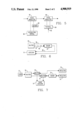
- FIG. 1 illustrates a fiber optic accelerometer vibration measuring system in accordance with the present invention
- FIG. 2 illustrate the details of construction of the sensor 24 in FIG. 1;
- FIG. 3 depicts a configuration for biasing the acceleration signals
- FIG. 4 also depicts a system for biasing the vibration signals
- FIG. 5 illustrates another method of biasing the acceleration signals
- FIG. 6 illustrates a system which will eliminate low frequency phase shifts due to mechanical effects
- FIG. 7 illustrates a system which will eliminate low frequency mechanical effects along with doubling the sensitivity of the vibration sensor 24.
- FIG. 1 A wide bandwidth acceleration sensing system for a load mass 10 using a conventional laser 12 and a conventional optical phase shift detector 14 is illustrated in FIG. 1.
- a suitable conventional laser 12 can be obtained from Spectra Diode Labs, Inc. of San Jose, Calif. as model SDL-2402-HZ while a conventional detector 14, such as used in fiber optic gyroscopes, is preferred.
- the laser 12 produces a coherent beam transmitted over an optical fiber 16 to a conventional beam splitter 18.
- One half of the split beam is transmitted over a conventional optical fiber 20 to the phase shift detector 14 and is used as the reference beam with which a vibraton responsive phase shifted beam is compared to determine vibration.
- the splitter 18 transmits the other split beam (the sensing beam) over optical fiber 22 to a vibration sensor 24 which is physically coupled to the load mass 10.
- the sensor 24 includes a conventional piezoelectric crystal 26, available from Endevco of San Juan Capistrano, Calif., which will produce an electrical signal responsive to the compression and expansion or flexing of the crystal caused by the load mass 10.
- vibration sensors such as a velocity sensor
- the crystal 26 has a frequency response range from about 1 hertz to several hundred megahertz.
- the electrical signal produced by the crystal 26 is applied to a phase modulator 28 such as the Amphenol LINI-GUIDE phase modulator series 947.
- the phase modulator 28 produces a phase modulated light beam which is transmitted to the optical phase shift detector 14 over optical fiber 30.
- the combination of the piezoelectric crystal 26 and phase modulator 28 produces a sensor 24 with a temperature drift coefficient of essentially zero from 201/2 C. to 1001/2 C.
- the sensor 24 is typically less than 1 cubic centimeter in size and is capable of producing a linear acceleration signal with a wide frequency range up to several hundred megahertz.
- phase shift detector 14 reproduces the electrical signal of the piezoelectric crystal 26 and the reproduced signal is then treated the same as the signal produced directly by the crystal 26. Because the voltage produced by the crystal 26 is lower for lower frequencies some linearization of the detector output signal is necessary at the lower frequencies. This compensation can be provided by those of ordinary skill in the art dependent on the particular application.
- the details of the phase modulator 28 in combination with the piezoelectric crystal 26 and load mass 10 are illustrated in FIG. 2.
- the light applied to the modulator 28 by the optical waveguide 22 is in the TE (Transverse Electrical) mode and is coupled to the modulator 28 by a fiber optic connector 40.
- the fiber optic connector 40 connects the optical fiber 22 to a titanium diffused wave guide 42 created in a lithium niobate substrate 44.
- the light beam is phase modulated by the application of a potential to two electrodes 46 by conductors 48 connected to the crystal 26.
- the waveguide 42 is coupled to fiber 30 by a connector 50.
- the components 40-46 and 50 are all part of the preferred modulator 28 previously mentioned.
- the crystal 26 produces an electric potential in response to the force exerted by the load 10 on the crystal 26.
- the potential causes a charge transfer to the electrodes 46 of the modulator 28.
- the voltage across the optical waveguide 42 develops a strong electric field therein that changes the index of refraction of the material.
- the change in refractive index causes a change in the light propagation speed which results in a phase shift in the light beam relative to the reference beam. Because the phase of the light beam carries the acceleration signal, the signal is independent of light source intensity.
- a battery 60 is connected between the piezoelectric crystal 26 and phase modulator 28 on one of the conductors to the phase modulator 28.
- the battery will provide a constant phase shift offset. Without a battery bias the phase shift passes through zero twice each cycle and the detector 14 will produce a rectified vibration signal. The battery bias will cause the detector output signal to always be positive and will also enhance the output signal level of low frequency vibration signals. Because the battery 60 delivers no net power to the phase modulator 28 or the crystal 26 the battery 60 will have a very long life.
- FIG. 4 illustrates a second biasing scheme which uses light from a third source such as another optical fiber 62 to cause a conventional silicon photocell 64 to apply a bias to one lead of the piezoelectric crystal 26.
- a third source such as another optical fiber 62
- the use of a photocell 64 not only allows the application of a constant phase shift DC type offset to bias the optical chip but will allow a calibration light signal to be transferred over the fiber 62 to allow for calibration and testing of the sensor 24.
- the photocell 64 can also be used to AC modulate the DC bias to produce beats in the piezoelectric crystal signal. Because photocell 64 is driving essentially infinite an impedance little power need be delivered by the fiber 64.
- FIG. 5 illustrates a third method of producing a bias signal along with a calibration signal using a system that is electrically isolated from the vibration signal.
- This system uses tWo phase modulators 66 and 68 in series.
- the off the shelf modulator could be changed internally to include two pairs of electrodes 46 providing a two input device.
- performance can be improved by providing a feedback signal to the sensor through the photocell 62 to continuously bias the phase shift introduced in the light by the crystal 26 to keep the vibration induced phase shift in the most sensitive region. For example, if a 180° phase shift is produced by the bias, the light beams will nearly cancel each other and small phase shifts produced by the crystal 26 can be hard to detect. The best bias would tend to keep the bias and vibration phase shifted beam about 90° out of phase with the reference beam.
- the optical fibers are subject to mechanical stress which can produce low frequency phase shift noise in the beam, a system as illustrated in FIG. 6 will substantially eliminate this type of noise.
- the fibers 20, 22 and 30 travel the same or a parallel physical pathway to the sensor 24 and from the sensor 24 to the detector 14 thereby subjecting the reference beam and sensing beam to the same phase shift.
- conventional fiber optic cable bundles include at least three fibers a conventional cable bundle is uniquely suited to noise reduction due to mechanical stress on the fibers as well as transferring the DC bias and calibration light beam.
- FIG. 7 illustrates a system which not only removes the mechanical bias noise but also doubles the sensitivity of the sensor 24.
- the beam from laser 12 is split by splitter 18 and split again by conventional splitters 70 and 72.
- One of the split beams (the sensing b®am) passes through sensor 24 and is reflected by a conventional reflector 74 while the parallel physical path of the split beam (the reference beam) is reflected by conventional reflector 76 at the same location.
- the return beam from reflector 74 passes back through sensor 24 and as a result is phase modulated twice by the vibration of the load 10. This doubly phase modulated sensing beam is applied to detector 14 along with the reference beam.
Abstract
Description
Claims (18)
Priority Applications (7)
| Application Number | Priority Date | Filing Date | Title |
|---|---|---|---|
| US07/209,124 US4900919A (en) | 1988-06-20 | 1988-06-20 | Wide bandwidth fiber optic accelerometer |
| CN89104098A CN1038701A (en) | 1988-06-20 | 1989-06-09 | Wide bandwidth fiber optic accelerometer |
| CA000603035A CA1326602C (en) | 1988-06-20 | 1989-06-16 | Wide bandwidth fiber optic accelerometer |
| IT8941635A IT1232812B (en) | 1988-06-20 | 1989-06-19 | FIBER OPTICAL ACCELEROMETER WITH WIDE BANDWIDTH |
| KR1019890008407A KR0153277B1 (en) | 1988-06-20 | 1989-06-19 | Wide bandwidth fiber optic accelerometer |
| ES8902133A ES2014665A6 (en) | 1988-06-20 | 1989-06-19 | Wide bandwidth fiber optic accelerometer |
| JP1158134A JP2901995B2 (en) | 1988-06-20 | 1989-06-20 | Fiber optic monitor for measuring vibration and acceleration of a load object |
Applications Claiming Priority (1)
| Application Number | Priority Date | Filing Date | Title |
|---|---|---|---|
| US07/209,124 US4900919A (en) | 1988-06-20 | 1988-06-20 | Wide bandwidth fiber optic accelerometer |
Publications (1)
| Publication Number | Publication Date |
|---|---|
| US4900919A true US4900919A (en) | 1990-02-13 |
Family
ID=22777437
Family Applications (1)
| Application Number | Title | Priority Date | Filing Date |
|---|---|---|---|
| US07/209,124 Expired - Fee Related US4900919A (en) | 1988-06-20 | 1988-06-20 | Wide bandwidth fiber optic accelerometer |
Country Status (7)
| Country | Link |
|---|---|
| US (1) | US4900919A (en) |
| JP (1) | JP2901995B2 (en) |
| KR (1) | KR0153277B1 (en) |
| CN (1) | CN1038701A (en) |
| CA (1) | CA1326602C (en) |
| ES (1) | ES2014665A6 (en) |
| IT (1) | IT1232812B (en) |
Cited By (12)
| Publication number | Priority date | Publication date | Assignee | Title |
|---|---|---|---|---|
| US5182487A (en) * | 1989-09-19 | 1993-01-26 | Murata Mfg. Co., Ltd. | Deflection yoke device |
| US5335548A (en) * | 1992-06-19 | 1994-08-09 | The United States Of America As Represented By The Department Of Energy | Non-linear optical crystal vibration sensing device |
| US5338928A (en) * | 1993-04-28 | 1994-08-16 | General Electric Company | System and method for controlling deformation of a structure having a phase shift detector |
| US5377523A (en) * | 1991-07-19 | 1995-01-03 | Mitsubishi Petrochemical Co., Ltd. | Acceleration sensor suitable for self-checking and a self-checking circuit therefore |
| US5461914A (en) * | 1994-03-14 | 1995-10-31 | The Regents Of The University Of California | Optical fiber gravity meter |
| US5652390A (en) * | 1995-12-07 | 1997-07-29 | Melkoumian; Baghrat V. | Method and device for autonomous measurement of an irregular movement based on resonatory sensor |
| US6175108B1 (en) | 1998-01-30 | 2001-01-16 | Cidra Corporation | Accelerometer featuring fiber optic bragg grating sensor for providing multiplexed multi-axis acceleration sensing |
| US6191414B1 (en) | 1998-06-05 | 2001-02-20 | Cidra Corporation | Composite form as a component for a pressure transducer |
| US6233374B1 (en) | 1999-06-04 | 2001-05-15 | Cidra Corporation | Mandrel-wound fiber optic pressure sensor |
| US20060219009A1 (en) * | 2005-03-31 | 2006-10-05 | Maas Steven J | Optical accelerometer, optical inclinometer and seismic sensor system using such accelerometer and inclinometer |
| US20080041162A1 (en) * | 2006-08-15 | 2008-02-21 | Siemens Power Generation, Inc. | High bandwidth fiber optic vibration sensor |
| US20080225375A1 (en) * | 2004-09-07 | 2008-09-18 | Raytheon Company | Optically frequency generated scanned active array |
Families Citing this family (4)
| Publication number | Priority date | Publication date | Assignee | Title |
|---|---|---|---|---|
| KR100233052B1 (en) * | 1997-11-04 | 1999-12-01 | 윤종용 | Power supply circuit of microwave oven |
| CN101788569B (en) * | 2009-12-31 | 2012-05-23 | 中国科学院声学研究所 | Optical fiber acceleration transducer probe and acceleration transducer system |
| CN110133321B (en) * | 2019-05-13 | 2020-11-24 | 浙江大学 | Monolithic integrated optical accelerometer based on phase detection |
| CN110133322B (en) * | 2019-05-13 | 2020-08-25 | 浙江大学 | Monolithic integrated optical accelerometer based on electro-optical effect |
Citations (4)
| Publication number | Priority date | Publication date | Assignee | Title |
|---|---|---|---|---|
| US4085349A (en) * | 1976-03-12 | 1978-04-18 | Ird Mechanalysis, Inc. | Piezo electric transducer for measuring instantaneous vibration velocity |
| US4233847A (en) * | 1979-07-02 | 1980-11-18 | Walker Clifford G | Passive laser accelerometer |
| US4428234A (en) * | 1982-03-25 | 1984-01-31 | Walker Clifford G | Phase detection laser accelerometer |
| US4671113A (en) * | 1983-02-17 | 1987-06-09 | Carome Edward F | Fiber optic accelerometer |
-
1988
- 1988-06-20 US US07/209,124 patent/US4900919A/en not_active Expired - Fee Related
-
1989
- 1989-06-09 CN CN89104098A patent/CN1038701A/en active Pending
- 1989-06-16 CA CA000603035A patent/CA1326602C/en not_active Expired - Fee Related
- 1989-06-19 IT IT8941635A patent/IT1232812B/en active
- 1989-06-19 KR KR1019890008407A patent/KR0153277B1/en not_active IP Right Cessation
- 1989-06-19 ES ES8902133A patent/ES2014665A6/en not_active Expired - Lifetime
- 1989-06-20 JP JP1158134A patent/JP2901995B2/en not_active Expired - Lifetime
Patent Citations (4)
| Publication number | Priority date | Publication date | Assignee | Title |
|---|---|---|---|---|
| US4085349A (en) * | 1976-03-12 | 1978-04-18 | Ird Mechanalysis, Inc. | Piezo electric transducer for measuring instantaneous vibration velocity |
| US4233847A (en) * | 1979-07-02 | 1980-11-18 | Walker Clifford G | Passive laser accelerometer |
| US4428234A (en) * | 1982-03-25 | 1984-01-31 | Walker Clifford G | Phase detection laser accelerometer |
| US4671113A (en) * | 1983-02-17 | 1987-06-09 | Carome Edward F | Fiber optic accelerometer |
Cited By (15)
| Publication number | Priority date | Publication date | Assignee | Title |
|---|---|---|---|---|
| US5182487A (en) * | 1989-09-19 | 1993-01-26 | Murata Mfg. Co., Ltd. | Deflection yoke device |
| US5377523A (en) * | 1991-07-19 | 1995-01-03 | Mitsubishi Petrochemical Co., Ltd. | Acceleration sensor suitable for self-checking and a self-checking circuit therefore |
| US5335548A (en) * | 1992-06-19 | 1994-08-09 | The United States Of America As Represented By The Department Of Energy | Non-linear optical crystal vibration sensing device |
| US5338928A (en) * | 1993-04-28 | 1994-08-16 | General Electric Company | System and method for controlling deformation of a structure having a phase shift detector |
| US5461914A (en) * | 1994-03-14 | 1995-10-31 | The Regents Of The University Of California | Optical fiber gravity meter |
| US5637797A (en) * | 1994-03-14 | 1997-06-10 | The Regents Of The University Of California | Optical fiber gravity meter |
| US5652390A (en) * | 1995-12-07 | 1997-07-29 | Melkoumian; Baghrat V. | Method and device for autonomous measurement of an irregular movement based on resonatory sensor |
| US6175108B1 (en) | 1998-01-30 | 2001-01-16 | Cidra Corporation | Accelerometer featuring fiber optic bragg grating sensor for providing multiplexed multi-axis acceleration sensing |
| US6191414B1 (en) | 1998-06-05 | 2001-02-20 | Cidra Corporation | Composite form as a component for a pressure transducer |
| US6233374B1 (en) | 1999-06-04 | 2001-05-15 | Cidra Corporation | Mandrel-wound fiber optic pressure sensor |
| US20080225375A1 (en) * | 2004-09-07 | 2008-09-18 | Raytheon Company | Optically frequency generated scanned active array |
| US20060219009A1 (en) * | 2005-03-31 | 2006-10-05 | Maas Steven J | Optical accelerometer, optical inclinometer and seismic sensor system using such accelerometer and inclinometer |
| US7222534B2 (en) | 2005-03-31 | 2007-05-29 | Pgs Americas, Inc. | Optical accelerometer, optical inclinometer and seismic sensor system using such accelerometer and inclinometer |
| US20080041162A1 (en) * | 2006-08-15 | 2008-02-21 | Siemens Power Generation, Inc. | High bandwidth fiber optic vibration sensor |
| US7533572B2 (en) | 2006-08-15 | 2009-05-19 | Siemens Energy, Inc. | High bandwidth fiber optic vibration sensor |
Also Published As
| Publication number | Publication date |
|---|---|
| ES2014665A6 (en) | 1990-07-16 |
| KR900000722A (en) | 1990-01-31 |
| IT1232812B (en) | 1992-03-05 |
| IT8941635A0 (en) | 1989-06-19 |
| CN1038701A (en) | 1990-01-10 |
| CA1326602C (en) | 1994-02-01 |
| KR0153277B1 (en) | 1998-12-15 |
| JPH0240512A (en) | 1990-02-09 |
| JP2901995B2 (en) | 1999-06-07 |
Similar Documents
| Publication | Publication Date | Title |
|---|---|---|
| US4900919A (en) | Wide bandwidth fiber optic accelerometer | |
| CA1339426C (en) | Hydrophone demodulator circuit and method | |
| KR870001580B1 (en) | Passive interferometric sensor arrays | |
| EP0977022B1 (en) | Optical waveguide vibration sensor system for remote detection | |
| CA1320356C (en) | Multiplexed fiber optic sensor | |
| US4530603A (en) | Stabilized fiber optic sensor | |
| US4899042A (en) | Integrated optic field sensor consisting of an interferometer formed in substrate | |
| EP0092369B1 (en) | Light frequency change detecting method and apparatus | |
| US4776657A (en) | Electro-optic phase shifter with reduced input capacitance | |
| EP0135003B1 (en) | Apparatus for detecting the presence of coherent radiation in the presence of non-coherent ambient radiation | |
| US4208128A (en) | Interferometer gyro using heterodyne phase detection without severe light source coherence requirements | |
| US6559946B2 (en) | Method and apparatus to minimize effects of ASE in optical measurements | |
| US6285182B1 (en) | Electro-optic voltage sensor | |
| US4454418A (en) | Integrated optics transducer | |
| US4982151A (en) | Voltage measuring apparatus | |
| EP0134487A2 (en) | Coherent radiation detecting apparatus | |
| US5285257A (en) | Optic rotation sensing apparatus and related method including providing synchronous detection at a phase at which the AM noise is minimized | |
| JPH0447214A (en) | Optical fiber gyroscope | |
| JP2757816B2 (en) | Method for measuring characteristics of light intensity modulator and control method | |
| GB2109122A (en) | Acousto-optic isolator | |
| JPH09236783A (en) | Light intensity modulator and light wave range finder | |
| RU2130587C1 (en) | Method of processing of signal of circular interferometer of fiber-optics gyroscope (versions) | |
| JPH0522216B2 (en) | ||
| JPH0363008B2 (en) | ||
| EP0501002A2 (en) | Optic rotation sensing apparatus and related method |
Legal Events
| Date | Code | Title | Description |
|---|---|---|---|
| AS | Assignment |
Owner name: WESTINGHOUSE ELECTRIC CORPORATION, WESTINGHOUSE BU Free format text: ASSIGNMENT OF ASSIGNORS INTEREST.;ASSIGNOR:TWERDOCHLIB, MICHAEL;REEL/FRAME:004915/0997 Effective date: 19880609 |
|
| FPAY | Fee payment |
Year of fee payment: 4 |
|
| FPAY | Fee payment |
Year of fee payment: 8 |
|
| AS | Assignment |
Owner name: SIEMENS WESTINGHOUSE POWER CORPORATION, FLORIDA Free format text: ASSIGNMENT NUNC PRO TUNC EFFECTIVE AUGUST 19, 1998;ASSIGNOR:CBS CORPORATION, FORMERLY KNOWN AS WESTINGHOUSE ELECTRIC CORPORATION;REEL/FRAME:009605/0650 Effective date: 19980929 |
|
| FEPP | Fee payment procedure |
Free format text: PAYOR NUMBER ASSIGNED (ORIGINAL EVENT CODE: ASPN); ENTITY STATUS OF PATENT OWNER: LARGE ENTITY |
|
| REMI | Maintenance fee reminder mailed | ||
| LAPS | Lapse for failure to pay maintenance fees | ||
| STCH | Information on status: patent discontinuation |
Free format text: PATENT EXPIRED DUE TO NONPAYMENT OF MAINTENANCE FEES UNDER 37 CFR 1.362 |
|
| FP | Lapsed due to failure to pay maintenance fee |
Effective date: 20020213 |