US4899858A - Method and control system for updating of control parameter value indicative of master clutch point of incipient engagement - Google Patents
Method and control system for updating of control parameter value indicative of master clutch point of incipient engagement Download PDFInfo
- Publication number
- US4899858A US4899858A US07/318,100 US31810089A US4899858A US 4899858 A US4899858 A US 4899858A US 31810089 A US31810089 A US 31810089A US 4899858 A US4899858 A US 4899858A
- Authority
- US
- United States
- Prior art keywords
- clutch
- input shaft
- value
- incipient engagement
- engagement
- Prior art date
- Legal status (The legal status is an assumption and is not a legal conclusion. Google has not performed a legal analysis and makes no representation as to the accuracy of the status listed.)
- Expired - Lifetime
Links
- 238000000034 method Methods 0.000 title claims description 25
- 230000005540 biological transmission Effects 0.000 claims abstract description 54
- 230000009347 mechanical transmission Effects 0.000 claims abstract description 14
- 238000012545 processing Methods 0.000 claims description 15
- 230000007935 neutral effect Effects 0.000 claims description 7
- 230000000979 retarding effect Effects 0.000 claims description 6
- 238000012935 Averaging Methods 0.000 claims description 5
- 230000000694 effects Effects 0.000 claims description 4
- 230000004044 response Effects 0.000 claims description 3
- 238000012546 transfer Methods 0.000 claims description 3
- 230000008878 coupling Effects 0.000 claims 2
- 238000010168 coupling process Methods 0.000 claims 2
- 238000005859 coupling reaction Methods 0.000 claims 2
- 230000010365 information processing Effects 0.000 claims 2
- 230000008859 change Effects 0.000 abstract description 13
- 239000000446 fuel Substances 0.000 description 8
- 238000004364 calculation method Methods 0.000 description 3
- 206010000210 abortion Diseases 0.000 description 2
- 230000001133 acceleration Effects 0.000 description 2
- 238000010276 construction Methods 0.000 description 2
- 230000001934 delay Effects 0.000 description 2
- 239000012530 fluid Substances 0.000 description 2
- 230000007774 longterm Effects 0.000 description 2
- 230000007246 mechanism Effects 0.000 description 2
- 238000012360 testing method Methods 0.000 description 2
- 150000001875 compounds Chemical class 0.000 description 1
- 238000013461 design Methods 0.000 description 1
- XDDAORKBJWWYJS-UHFFFAOYSA-N glyphosate Chemical compound OC(=O)CNCP(O)(O)=O XDDAORKBJWWYJS-UHFFFAOYSA-N 0.000 description 1
- 230000006872 improvement Effects 0.000 description 1
- 230000000977 initiatory effect Effects 0.000 description 1
- 238000012986 modification Methods 0.000 description 1
- 230000004048 modification Effects 0.000 description 1
- 238000012544 monitoring process Methods 0.000 description 1
- 230000008707 rearrangement Effects 0.000 description 1
- 230000002441 reversible effect Effects 0.000 description 1
- 238000005096 rolling process Methods 0.000 description 1
- 238000006467 substitution reaction Methods 0.000 description 1
- 230000001360 synchronised effect Effects 0.000 description 1
Images
Classifications
-
- B—PERFORMING OPERATIONS; TRANSPORTING
- B60—VEHICLES IN GENERAL
- B60W—CONJOINT CONTROL OF VEHICLE SUB-UNITS OF DIFFERENT TYPE OR DIFFERENT FUNCTION; CONTROL SYSTEMS SPECIALLY ADAPTED FOR HYBRID VEHICLES; ROAD VEHICLE DRIVE CONTROL SYSTEMS FOR PURPOSES NOT RELATED TO THE CONTROL OF A PARTICULAR SUB-UNIT
- B60W10/00—Conjoint control of vehicle sub-units of different type or different function
- B60W10/04—Conjoint control of vehicle sub-units of different type or different function including control of propulsion units
- B60W10/06—Conjoint control of vehicle sub-units of different type or different function including control of propulsion units including control of combustion engines
-
- B—PERFORMING OPERATIONS; TRANSPORTING
- B60—VEHICLES IN GENERAL
- B60W—CONJOINT CONTROL OF VEHICLE SUB-UNITS OF DIFFERENT TYPE OR DIFFERENT FUNCTION; CONTROL SYSTEMS SPECIALLY ADAPTED FOR HYBRID VEHICLES; ROAD VEHICLE DRIVE CONTROL SYSTEMS FOR PURPOSES NOT RELATED TO THE CONTROL OF A PARTICULAR SUB-UNIT
- B60W10/00—Conjoint control of vehicle sub-units of different type or different function
- B60W10/02—Conjoint control of vehicle sub-units of different type or different function including control of driveline clutches
-
- B—PERFORMING OPERATIONS; TRANSPORTING
- B60—VEHICLES IN GENERAL
- B60W—CONJOINT CONTROL OF VEHICLE SUB-UNITS OF DIFFERENT TYPE OR DIFFERENT FUNCTION; CONTROL SYSTEMS SPECIALLY ADAPTED FOR HYBRID VEHICLES; ROAD VEHICLE DRIVE CONTROL SYSTEMS FOR PURPOSES NOT RELATED TO THE CONTROL OF A PARTICULAR SUB-UNIT
- B60W10/00—Conjoint control of vehicle sub-units of different type or different function
- B60W10/04—Conjoint control of vehicle sub-units of different type or different function including control of propulsion units
-
- B—PERFORMING OPERATIONS; TRANSPORTING
- B60—VEHICLES IN GENERAL
- B60W—CONJOINT CONTROL OF VEHICLE SUB-UNITS OF DIFFERENT TYPE OR DIFFERENT FUNCTION; CONTROL SYSTEMS SPECIALLY ADAPTED FOR HYBRID VEHICLES; ROAD VEHICLE DRIVE CONTROL SYSTEMS FOR PURPOSES NOT RELATED TO THE CONTROL OF A PARTICULAR SUB-UNIT
- B60W30/00—Purposes of road vehicle drive control systems not related to the control of a particular sub-unit, e.g. of systems using conjoint control of vehicle sub-units
- B60W30/18—Propelling the vehicle
- B60W30/18009—Propelling the vehicle related to particular drive situations
- B60W30/18027—Drive off, accelerating from standstill
-
- B—PERFORMING OPERATIONS; TRANSPORTING
- B60—VEHICLES IN GENERAL
- B60W—CONJOINT CONTROL OF VEHICLE SUB-UNITS OF DIFFERENT TYPE OR DIFFERENT FUNCTION; CONTROL SYSTEMS SPECIALLY ADAPTED FOR HYBRID VEHICLES; ROAD VEHICLE DRIVE CONTROL SYSTEMS FOR PURPOSES NOT RELATED TO THE CONTROL OF A PARTICULAR SUB-UNIT
- B60W30/00—Purposes of road vehicle drive control systems not related to the control of a particular sub-unit, e.g. of systems using conjoint control of vehicle sub-units
- B60W30/18—Propelling the vehicle
- B60W30/1819—Propulsion control with control means using analogue circuits, relays or mechanical links
-
- F—MECHANICAL ENGINEERING; LIGHTING; HEATING; WEAPONS; BLASTING
- F16—ENGINEERING ELEMENTS AND UNITS; GENERAL MEASURES FOR PRODUCING AND MAINTAINING EFFECTIVE FUNCTIONING OF MACHINES OR INSTALLATIONS; THERMAL INSULATION IN GENERAL
- F16D—COUPLINGS FOR TRANSMITTING ROTATION; CLUTCHES; BRAKES
- F16D48/00—External control of clutches
- F16D48/06—Control by electric or electronic means, e.g. of fluid pressure
- F16D48/066—Control of fluid pressure, e.g. using an accumulator
-
- B—PERFORMING OPERATIONS; TRANSPORTING
- B60—VEHICLES IN GENERAL
- B60W—CONJOINT CONTROL OF VEHICLE SUB-UNITS OF DIFFERENT TYPE OR DIFFERENT FUNCTION; CONTROL SYSTEMS SPECIALLY ADAPTED FOR HYBRID VEHICLES; ROAD VEHICLE DRIVE CONTROL SYSTEMS FOR PURPOSES NOT RELATED TO THE CONTROL OF A PARTICULAR SUB-UNIT
- B60W2510/00—Input parameters relating to a particular sub-units
- B60W2510/02—Clutches
- B60W2510/0208—Clutch engagement state, e.g. engaged or disengaged
- B60W2510/0225—Clutch actuator position
-
- B—PERFORMING OPERATIONS; TRANSPORTING
- B60—VEHICLES IN GENERAL
- B60W—CONJOINT CONTROL OF VEHICLE SUB-UNITS OF DIFFERENT TYPE OR DIFFERENT FUNCTION; CONTROL SYSTEMS SPECIALLY ADAPTED FOR HYBRID VEHICLES; ROAD VEHICLE DRIVE CONTROL SYSTEMS FOR PURPOSES NOT RELATED TO THE CONTROL OF A PARTICULAR SUB-UNIT
- B60W2510/00—Input parameters relating to a particular sub-units
- B60W2510/06—Combustion engines, Gas turbines
- B60W2510/0638—Engine speed
-
- B—PERFORMING OPERATIONS; TRANSPORTING
- B60—VEHICLES IN GENERAL
- B60W—CONJOINT CONTROL OF VEHICLE SUB-UNITS OF DIFFERENT TYPE OR DIFFERENT FUNCTION; CONTROL SYSTEMS SPECIALLY ADAPTED FOR HYBRID VEHICLES; ROAD VEHICLE DRIVE CONTROL SYSTEMS FOR PURPOSES NOT RELATED TO THE CONTROL OF A PARTICULAR SUB-UNIT
- B60W2510/00—Input parameters relating to a particular sub-units
- B60W2510/10—Change speed gearings
- B60W2510/1015—Input shaft speed, e.g. turbine speed
-
- F—MECHANICAL ENGINEERING; LIGHTING; HEATING; WEAPONS; BLASTING
- F16—ENGINEERING ELEMENTS AND UNITS; GENERAL MEASURES FOR PRODUCING AND MAINTAINING EFFECTIVE FUNCTIONING OF MACHINES OR INSTALLATIONS; THERMAL INSULATION IN GENERAL
- F16D—COUPLINGS FOR TRANSMITTING ROTATION; CLUTCHES; BRAKES
- F16D2500/00—External control of clutches by electric or electronic means
- F16D2500/10—System to be controlled
- F16D2500/108—Gear
- F16D2500/1081—Actuation type
- F16D2500/1083—Automated manual transmission
-
- F—MECHANICAL ENGINEERING; LIGHTING; HEATING; WEAPONS; BLASTING
- F16—ENGINEERING ELEMENTS AND UNITS; GENERAL MEASURES FOR PRODUCING AND MAINTAINING EFFECTIVE FUNCTIONING OF MACHINES OR INSTALLATIONS; THERMAL INSULATION IN GENERAL
- F16D—COUPLINGS FOR TRANSMITTING ROTATION; CLUTCHES; BRAKES
- F16D2500/00—External control of clutches by electric or electronic means
- F16D2500/10—System to be controlled
- F16D2500/108—Gear
- F16D2500/1081—Actuation type
- F16D2500/1085—Automatic transmission
-
- F—MECHANICAL ENGINEERING; LIGHTING; HEATING; WEAPONS; BLASTING
- F16—ENGINEERING ELEMENTS AND UNITS; GENERAL MEASURES FOR PRODUCING AND MAINTAINING EFFECTIVE FUNCTIONING OF MACHINES OR INSTALLATIONS; THERMAL INSULATION IN GENERAL
- F16D—COUPLINGS FOR TRANSMITTING ROTATION; CLUTCHES; BRAKES
- F16D2500/00—External control of clutches by electric or electronic means
- F16D2500/30—Signal inputs
- F16D2500/304—Signal inputs from the clutch
- F16D2500/30401—On-off signal indicating the engage or disengaged position of the clutch
-
- F—MECHANICAL ENGINEERING; LIGHTING; HEATING; WEAPONS; BLASTING
- F16—ENGINEERING ELEMENTS AND UNITS; GENERAL MEASURES FOR PRODUCING AND MAINTAINING EFFECTIVE FUNCTIONING OF MACHINES OR INSTALLATIONS; THERMAL INSULATION IN GENERAL
- F16D—COUPLINGS FOR TRANSMITTING ROTATION; CLUTCHES; BRAKES
- F16D2500/00—External control of clutches by electric or electronic means
- F16D2500/30—Signal inputs
- F16D2500/306—Signal inputs from the engine
- F16D2500/3067—Speed of the engine
-
- F—MECHANICAL ENGINEERING; LIGHTING; HEATING; WEAPONS; BLASTING
- F16—ENGINEERING ELEMENTS AND UNITS; GENERAL MEASURES FOR PRODUCING AND MAINTAINING EFFECTIVE FUNCTIONING OF MACHINES OR INSTALLATIONS; THERMAL INSULATION IN GENERAL
- F16D—COUPLINGS FOR TRANSMITTING ROTATION; CLUTCHES; BRAKES
- F16D2500/00—External control of clutches by electric or electronic means
- F16D2500/30—Signal inputs
- F16D2500/308—Signal inputs from the transmission
- F16D2500/3081—Signal inputs from the transmission from the input shaft
- F16D2500/30816—Speed of the input shaft
-
- F—MECHANICAL ENGINEERING; LIGHTING; HEATING; WEAPONS; BLASTING
- F16—ENGINEERING ELEMENTS AND UNITS; GENERAL MEASURES FOR PRODUCING AND MAINTAINING EFFECTIVE FUNCTIONING OF MACHINES OR INSTALLATIONS; THERMAL INSULATION IN GENERAL
- F16D—COUPLINGS FOR TRANSMITTING ROTATION; CLUTCHES; BRAKES
- F16D2500/00—External control of clutches by electric or electronic means
- F16D2500/50—Problem to be solved by the control system
- F16D2500/502—Relating the clutch
- F16D2500/50245—Calibration or recalibration of the clutch touch-point
- F16D2500/50251—During operation
- F16D2500/50254—Brake actuated
-
- F—MECHANICAL ENGINEERING; LIGHTING; HEATING; WEAPONS; BLASTING
- F16—ENGINEERING ELEMENTS AND UNITS; GENERAL MEASURES FOR PRODUCING AND MAINTAINING EFFECTIVE FUNCTIONING OF MACHINES OR INSTALLATIONS; THERMAL INSULATION IN GENERAL
- F16D—COUPLINGS FOR TRANSMITTING ROTATION; CLUTCHES; BRAKES
- F16D2500/00—External control of clutches by electric or electronic means
- F16D2500/50—Problem to be solved by the control system
- F16D2500/504—Relating the engine
- F16D2500/5045—Control of engine at idle, i.e. controlling engine idle conditions, e.g. idling speed
-
- F—MECHANICAL ENGINEERING; LIGHTING; HEATING; WEAPONS; BLASTING
- F16—ENGINEERING ELEMENTS AND UNITS; GENERAL MEASURES FOR PRODUCING AND MAINTAINING EFFECTIVE FUNCTIONING OF MACHINES OR INSTALLATIONS; THERMAL INSULATION IN GENERAL
- F16D—COUPLINGS FOR TRANSMITTING ROTATION; CLUTCHES; BRAKES
- F16D2500/00—External control of clutches by electric or electronic means
- F16D2500/70—Details about the implementation of the control system
- F16D2500/704—Output parameters from the control unit; Target parameters to be controlled
- F16D2500/70402—Actuator parameters
- F16D2500/7041—Position
- F16D2500/70414—Quick displacement to clutch touch point
-
- F—MECHANICAL ENGINEERING; LIGHTING; HEATING; WEAPONS; BLASTING
- F16—ENGINEERING ELEMENTS AND UNITS; GENERAL MEASURES FOR PRODUCING AND MAINTAINING EFFECTIVE FUNCTIONING OF MACHINES OR INSTALLATIONS; THERMAL INSULATION IN GENERAL
- F16D—COUPLINGS FOR TRANSMITTING ROTATION; CLUTCHES; BRAKES
- F16D2500/00—External control of clutches by electric or electronic means
- F16D2500/70—Details about the implementation of the control system
- F16D2500/704—Output parameters from the control unit; Target parameters to be controlled
- F16D2500/70464—Transmission parameters
- F16D2500/70466—Input shaft
- F16D2500/70472—Input shaft speed
-
- F—MECHANICAL ENGINEERING; LIGHTING; HEATING; WEAPONS; BLASTING
- F16—ENGINEERING ELEMENTS AND UNITS; GENERAL MEASURES FOR PRODUCING AND MAINTAINING EFFECTIVE FUNCTIONING OF MACHINES OR INSTALLATIONS; THERMAL INSULATION IN GENERAL
- F16D—COUPLINGS FOR TRANSMITTING ROTATION; CLUTCHES; BRAKES
- F16D2500/00—External control of clutches by electric or electronic means
- F16D2500/70—Details about the implementation of the control system
- F16D2500/706—Strategy of control
- F16D2500/70605—Adaptive correction; Modifying control system parameters, e.g. gains, constants, look-up tables
-
- F—MECHANICAL ENGINEERING; LIGHTING; HEATING; WEAPONS; BLASTING
- F16—ENGINEERING ELEMENTS AND UNITS; GENERAL MEASURES FOR PRODUCING AND MAINTAINING EFFECTIVE FUNCTIONING OF MACHINES OR INSTALLATIONS; THERMAL INSULATION IN GENERAL
- F16H—GEARING
- F16H61/00—Control functions within control units of change-speed- or reversing-gearings for conveying rotary motion ; Control of exclusively fluid gearing, friction gearing, gearings with endless flexible members or other particular types of gearing
- F16H2061/0075—Control functions within control units of change-speed- or reversing-gearings for conveying rotary motion ; Control of exclusively fluid gearing, friction gearing, gearings with endless flexible members or other particular types of gearing characterised by a particular control method
- F16H2061/0087—Adaptive control, e.g. the control parameters adapted by learning
Definitions
- the present invention relates to clutch controls for automatically controlling the engagement and disengagement of transmission system master clutches and in particular relates to clutch controls for master clutches utilized with automatic/semi-automatic mechanical transmission systems. More particularly, the present invention relates to an improved automatic clutch control method and system, typically having a modulated engagement mode wherein the master friction clutch is moved rapidly from the fully disengaged position to the position of almost incipient, or about incipient, engagement and then fully engaged in a modulated manner and wherein the position of almost incipient or incipient engagement is determined by the value of a monitored clutch parameter, which value is periodically updated usually in a vehicle start-up routine, to adjust value of the parameter for wear, adjustments or the like.
- the master friction clutch is modulated between fully disengaged and fully engaged conditions, i.e. is partially engaged, according to certain input parameters, to maintain the engine speed at a set value above idle speed and/or to achieve smooth starts.
- the set engine speed value is throttle position modulated to provide appropriate starting torque and the clutch is moved toward engagement and disengagement, respectively, as the engine speed increases above and falls below, respectively, the set engine speed value.
- Movement of the clutch actuators from the fully disengaged to the incipient engagement position in any manner other than the fastest possible manner is undesirable as control of the system, i.e., control of engine and/or input shaft speed, by varying amount of clutch engagement (i.e. slip) is not possible during this portion of actuator movement and delays in achieving at least incipient engagement make closed loop control of the system more difficult. This is especially true as movement from the fully disengaged condition to incipient engagement may require up to about fifty percent (50%) of the total actuator disengagement and up to about thirty five percent (35%) of the full actuator supply pressure.
- An automatic clutch control system including means to move the controlled friction clutch from the fully disengaged condition towards the fully engaged condition as rapidly as possible, until sensing actual initial engagement of the clutch friction linings, is disclosed in above-mentioned U.S. Pat. No. 4,401,200. While this prior art system is an improvement over the previously existing systems, this system is not totally satisfactory as actual initial clutch engagement must occur and be sensed to initiate a change from the most rapid to a modulated engagement mode of operation and thus, due to sensing and change in mode of operation delays, the rapid clutch engagement is not limited to the free travel take-up only. Also a value of a monitored clutch actuator parameter, such as actuator pressure and/or lever position, corresponding to expected initial or incipient engagement is not set. Such a value, in addition to permitting most rapid clutch engagement to occur only until just prior to expected incipient engagement, provides a parameter which can be updated and compared to previously determined values to sense system damage and/or operating errors.
- an automatic master friction clutch control method and system preferably for use in an automatic/semi-automatic mechanical transmission system, which typically has a modulated engagement mode of operation wherein the clutch actuators cause the clutch to move rapidly to the position of incipient, or preferably almost incipient, engagement and then move the clutch to a fully engaged position in a modulated manner in accordance with sensed, stored and/or calculated inputs and predetermined logic rules, wherein the point of expected incipient engagement is determined by the value of a monitored clutch parameter and is updated periodically to compensate for wear and the like.
- the value of the monitored parameter corresponding to master clutch incipient engagement is updated during a start-up routine in a manner wherein the point of incipient engagement is determined in a positive manner and, preferably, the value is calculated by a "rolling average” technique to filter out extraneous effects and the like.
- the system validates the stored value for the incipient engagement point (this is done by comparing the stored value with predefined limits, if the current value is outside the limits then it is initialized to a default value that approximates the correct point), awaits for the engine to be running at idle speed and for adequate air pressure to be present in the vehicle air system. When these conditions are valid, throttle control is temporarily taken away from the driver and the following test is run.
- the master clutch is fully disengaged and the input shaft of the transmission is brought to a stop by applying the input shaft brake. Next, air is slowly applied to the clutch actuator (causing the clutch to move towards the engaged position) until the input shaft is observed to turn against the resistance of the brake.
- the clutch actuator causing the clutch to move towards the engaged position
- the clutch is disengaged, the inertia brake is released, and throttle control is returned to the driver.
- the noted master clutch position (or other monitored clutch control parameter) is where the master clutch produces approximately 75 lb-ft of torque (this is the amount of torque the input shaft brake is capable of generating and is therefore the amount of clutch torque required to overcome the brake).
- the desired point of incipient engagement is where the clutch produces approximately 10 lb-ft of torque, making the point found an upper bound on the incipient engagement point.
- the instantaneous clutch incipient engagement point varies somewhat due to clutch and flywheel temperature and atmospheric conditions.
- an averaging technique is used.
- the old value for the clutch incipient engagement point is multiplied by N, a positive number such as 15, added to the determined point and then divided by N+1, 16. This produces a low pass filter that weights new information only 1/15th as highly as the old information. This insures that long term wear trends are taken into account without the system responding erratically due to minor variations in external circumstances.
- the clutch may then be caused to assume almost the expected incipient condition in a rapid unmodulated manner without overshooting the point of incipient engagement.
- an object of the present invention to provide an automatic clutch control method and system, preferably for an automatic or semi-automatic mechanical transmission system, wherein the control has a modulated engagement mode wherein the clutch is caused to move rapidly in an unmodulated manner from the fully disengaged to almost the incipient engagement position, and wherein the reference value of the control parameter utilized as an indication of the incipient engagement position of the clutch is periodically updated to compensate for wear and the like.
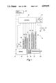
- FIG. 1 is a schematic illustration of an automatic mechanical transmission control system of the type advantageously utilizing the automatic clutch control system of the present invention.
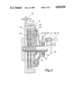
- FIG. 2 is a cross sectional view of a typical master friction clutch of the type automatically controlled by the present invention.
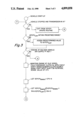
- FIG. 3 is a symbolic illustration, in the form of a flow chart, illustrating a preferred method of practicing the present invention.
- forward and rearward will refer to directions forward and rearward of the transmission or transmission shift bar housing assembly as normally mounted in a vehicle.
- the terms “rightward” and “leftward” will refer to directions in the drawings in connection with which the terminology is used.
- the terms “inwardly” and “outwardly” will refer to directions toward and away from, respectively, the geometric center of the apparatus being described.
- the terms “upward” and “downward” will refer to directions as taken in the drawings in connection with which the terminology is used. All foregoing terms include the normal derivatives and equivalents thereof.
- FIG. 1 schematically illustrates an automatic mechanical transmission system 10 including an automatic multi-speed compound change gear transmission 12 driven by a throttle controlled engine 14, such as a well known diesel engine, through a friction master clutch 16.
- An engine brake such as an exhaust brake 17 for retarding the rotational speed of engine 14 and an input shaft brake 18 which is effective to apply a retarding force to the input shaft upon disengagement of master clutch 16 are provided as is known in the prior art.
- the output of automatic transmission 12 is output shaft 20 which is adapted for driving connection to an appropriate vehicle component such as the differential of a drive axle, a transfer case or the like as is well known in the prior art.
- the above-mentioned power train components are acted upon and/or monitored by several devices. These devices include a throttle position or throttle opening monitor controlled vehicle throttle or other fuel throttling device 24, a fuel control device 26 for controlling the amount of fuel to be supplied to engine 14, an engine speed sensor 28 which senses the rotational speed of the engine, a clutch operator 30 which engages and disengages clutch 16 and which also supplies information as to the status of the clutch, an input brake operator 31, a transmission input shaft speed sensor 32, a transmission operator 34 which is effective to shift the transmission 12 into a selected gear ratio and to provide a signal indicative of the gear neutral condition and/or currently engaged ratio, and a transmission output shaft speed sensor 36.
- a vehicle brake monitor 38 senses actuation of vehicle brake pedal 40.
- a transmission operator for an automatic/semi-automatic mechanical transmission system may be seen by reference to U.S. Pat. No. 4,445,393, the disclosure of which is hereby incorporated by reference.
- the above-mentioned devices supply information to and/or accept commands from a central processing unit or control 42.
- the central processing unit 42 may include analogue and/or digital electronic calculation and logic circuitry, the specific configuration and structure of which forms no part of the present invention.
- the central processing unit 42 also receives information from a shift control assembly 44 by which the vehicle operator may select a reverse (R), neutral (N), or forward drive (D) mode of operation of the vehicle.
- An electrical power source (not shown) and/or source of pressurized fluid (not shown) provides electrical and/or pneumatic power to the various sensing, operating and/or processing units.
- a fault indicator or alarm 46 may display the identity of a specific fault or simply signal the existence of an unidentified fault.
- Drive train components and controls therefor of the type described above are known in the prior art and may be appreciated in greater detail by reference to above-mentioned U.S. Pat. Nos. 4,445,393; 4,361,060; 3,776,048, 4,038,889; 4,226,295; 4,702,127 and 4,722,237.
- Sensors 22, 28, 32, 36, 38 and 44 may be of any known type of construction for generating analogue or digital signals proportional to the parameter monitored thereby.
- operators 17, 18, 26, 30 and 34 may be of any known electrical, hydraulic, pneumatic or electropneumatic type for executing operations in response to command signals from processing unit 42 and/or for providing input signals thereto.
- Fuel control 26 will normally supply fuel to engine 14 in accordance with the operator's setting of throttle 24 but may supply a lesser (fuel dip) or greater (fuel boost) amount of fuel in accordance with commands from control unit 42..
- the purpose of the central processing unit 42 is to select, in accordance with a program, the optimal gear ratio at which the transmission should be operating and if necessary to command a gear change, or shift, into the selected optimal gear ratio based upon the current and/or stored information.
- the commands comprise commands to the transmission operator 34 to engage a desired gear ratio, to throttle control 26 to control the speed of the engine and to clutch operator 30 for proper operation of master clutch 16.
- a typical master friction clutch 16 of the type to be automatically controlled by the automatic clutch control system of the present invention may be seen by reference to FIG. 2. It is understood, of course, that the specific construction of the clutch and actuator therefore are shown for illustrative purposes and that the control system of the present invention is suitable for use in connection with clutches and/or operators therefor of differing structure.
- Clutch 16 illustrated is a typical two plate mechanical spring applied clutch which is mounted to an engine flywheel 48. Internal lugs 50 on the inner radius of the fly wheel 48 correspond to slots in the clutch pressure plate 52 and intermediate plate 54 causing these elements to rotate at engine speed. They are, however, free to move in an axial direction.
- Clutch driven discs 56 are splined to the transmission input shaft 58.
- Clutch torque is provided by engaging springs 60 acting through levers 62 to apply a pressure to pressure plate 52. This pressure squeezes the driven discs 56 and intermediate plate 54 between the pressure plate 52 and intermediate plate 54. The magnitude of the clutch torque is proportional to this pressure.
- the force provided by the spring 60 on the pressure plate 52 can be controlled by the axial position of the throw out bearing assembly 64.
- Throw out bearing assembly 64 can be moved in the axial direction by a control lever 66 mounted on a shaft 68.
- the shaft 68 is mounted in a clutch housing such that pivotal movement of the clutch control lever 66 will cause an axial movement of the throw out bearing assembly 64. In this manner, movement of control lever 66 can vary the force on pressure plate 52 and therefore the available clutch torque.
- a magnetic pickup 28 is mounted in the clutch housing and detects tooth passage of the gear teeth 70 located on the outer radius of the engine flywheel 48 to provide a signal proportional to engine speed.
- Pivotal movement of the control lever 66 is controlled by a piston, cylinder and control valve assembly 72.
- Lever 66 and assembly 72 comprise the clutch actuator 30.
- Control valve V may, as disclosed in above-mentioned U.S. Pat. Nos. 4,081,065 and 4,361,060 comprise fine and course ports for modulated and rapid movement of lever 66.
- a sensor 74 for sensing clutch actuator pressure and/or a sensor 76 for sensing lever/piston position may be provided for providing input signals to CPU 42.
- the automatic clutch control system of the present invention when utilized in connection with an automatic mechanical transmission system, comprises a portion of the central processing unit 42. As indicated above, the clutch control system of the present invention may be separate and distinct from any transmission control devices.
- the central processing unit may utilize discrete logic components or a programmed (by means of software and/or firmware) microprocessor. If a microprocessor is utilized, the discrete logic components/circuits, such as comparators, etc., are replaced by algorithm routines, etc., as is known in the prior art.
- the automatic clutch control system of the present invention is provided to automatically control the master friction clutch 16 connecting an engine 14 to a mechanical change gear transmission 12. Change gear transmissions are well known in the prior art and an example thereof may be seen by reference to U.S. Pat. No. 3,105,395, the disclosure of which is hereby incorporated by reference.
- the automatic clutch control system of the present invention controls operation of the clutch to engage and disengage same in accordance with certain current and/or stored parameters and logic rules.
- the automatic clutch control system preferably, will be similar to the clutch control systems illustrated and described in above-mentioned U.S. Pat. Nos. 4,401,200; 4,361,060; 4,081,065 and 3,752,284.
- the automatic clutch control will typically have several modes of operation, namely, a start from stop mode of operation wherein the clutch is engaged in a modulated manner and several gear change modes of operation when a vehicle transmission is shifted with the vehicle moving at above a given rate of speed.
- a start from stop mode of operation wherein the clutch is engaged in a modulated manner
- several gear change modes of operation when a vehicle transmission is shifted with the vehicle moving at above a given rate of speed.
- the master clutch is automatically caused to fully disengage at the initiation of a gear shift operation and automatically caused to fully re-engage at the completion of a gear shift operation at a rate of travel and/or slip which may be modulated or unmodulated.
- a considerably greater degree of control is required for operation of the clutch in the start from stop mode of operation.
- the master clutch in the start from stop mode of operation, the master clutch must be modulated between a fully disengaged and a fully engaged condition, or maintained at a predetermined partially engaged condition, in accordance with certain parameters which usually include at least engine speed and throttle position, to achieve an acceptably smooth start without stalling of the vehicle engine.
- the clutch is often maintained in a variably partially engaged condition, i.e. allowed a predetermined amount of slip, to maintain the engine speed and/or engine acceleration at above a predetermined value, which value is typically determined by engine idle speed and throttle position.
- the predetermined value is proportional to sensed throttle position expressed as a percentage of wide open throttle.
- the clutch In the gear shift modes of operation, if the drive line is engaged, the clutch is typically engaged in a modulated manner to achieve smooth engagement.
- the clutch is typically engaged in a rapid, unmodulated manner.
- the clutch 16 In the modulated modes of clutch engagement, especially in the start from stop mode of operation, the clutch 16 is utilized as an essential control element of the automatic/semi-automatic mechanical transmission system. As the clutch 16 can exercise no control over the system during that portion of engagement when it moves from the fully disengaged to the incipient engagement position, it is highly desirable to move the clutch as rapidly as possible between these positions during a modulated clutch engagement operation and to then control the degree of engagement of the clutch in a modulated manner, according to sensed, calculated and/or stored inputs and logic rules from the incipient engagement to fully engaged conditions thereof.
- a control parameter such as the reading from position sensor 76 or pressure sensor 74, corresponding to clutch incipient engagement is utilized.
- the control computer 42 determines the location of the clutch incipient engagement point. Since this point changes over time due to clutch wear and adjustment, it is advantageous for the system to have a means of determining it dynamically, i.e. to update the incipient engagement point control parameter value ("IEPCPV").
- the method utilized to update the IEPCPV is schematically illustrated in FIG. 3.
- the system Upon a cold start-up of the vehicle, the system checks at predetermined (10 millisecond) intervals that the vehicle is stopped and the transmission is in neutral. If at any time either of these conditions is not true then the IEPCPV update procedure aborts and normal transmission processing proceeds. If both conditions are true the system validates the stored value for the IEPCPV (this is done by comparing the stored value with predefined limits, if the current value is outside the limits then it is initialized to a default value that approximates the correct IEPCPV, waits for the engine to be running at idle speed and for adequate air pressure to be present in the vehicle air system. When these conditions are valid, throttle control is temporarily taken away from the driver and the following test or procedure is run.
- the master clutch 16 is fully disengaged and the input shaft 58 of the transmission is brought to a stop by applying the input shaft brake 18. Next, air is slowly applied to the clutch actuator 30 (causing the clutch to move towards the engaged position) until the input shaft is observed (sensor 32) to turn against the resistance of the input brake.
- the sensed value of the control parameter is noted, the clutch is disengaged, the inertia brake is released, and throttle control is returned to the driver.
- the noted clutch position is where the clutch produces approximately 75 lb-ft of torque (this is the amount of torque the input shaft brake is capable of generating and is therefore the amount of clutch torque required to overcome the brake).
- the desired point of incipient engagement is where the clutch produces approximately 10 lb-ft of torque, making the point found an upper bound on the low pressure point.
- Experimental results have shown that the actual point of the clutch can be closely approximated simply by subtracting a relatively small constant offset "K" from the point where the shaft began to turn. This calculation produces a snapshot of the IEPCPV at that instant in time.
- the instantaneous clutch incipient engagement point varies somewhat due to clutch and flywheel temperature and atmospheric conditions.
- an averaging technique is used.
- the old value for the IEPCPV (IEPCPV Last ) is multiplied by N (for example 15), added to the determined point "IEPC sensed " and then divided by N+1(i.e. 16). This produces a low pass filter that weighs new information only 1/15th as highly as the old information. This insures that long term wear trends are taken into account with the system responding erratically due to minor variations in external circumstances.
- an automatic clutch control system preferably for use in connection with a vehicle equipped with an automatic/semi-automatic mechanical transmission system, which includes logic for engaging the clutch in a modulated manner including moving the clutch from the fully disengaged to the incipient engagement position rapidly and then fully engaging the clutch in a modulated manner.
- the point of incipient, or preferably almost incipient, clutch engagement is achieved by commanding the clutch actuator to assume a condition wherein one or more of the monitored/controlled parameters is caused to assume a value (IEPCPV Last ) corresponding to incipient, or preferably almost incipient, clutch engagement, which value is periodically updated in a positive manner.
Landscapes
- Engineering & Computer Science (AREA)
- Chemical & Material Sciences (AREA)
- Combustion & Propulsion (AREA)
- Mechanical Engineering (AREA)
- Transportation (AREA)
- Automation & Control Theory (AREA)
- Physics & Mathematics (AREA)
- Fluid Mechanics (AREA)
- General Engineering & Computer Science (AREA)
- Hydraulic Clutches, Magnetic Clutches, Fluid Clutches, And Fluid Joints (AREA)
- Control Of Driving Devices And Active Controlling Of Vehicle (AREA)
Abstract
Description
Claims (10)
______________________________________
IEPCPU.sub.sensed
            =         the value of the input
                      signal indicative of clutch
                      position at incipient
                      engagement sensed in the
                      updating routine;
IEPCPU.sub.last
            =         the last stored value of
                      the input signal indicative
                      of clutch position at
                      incipient engagement; and
N           =         a positive number greater
                      than one.
______________________________________
______________________________________
IEPCPU.sub.sensed
            =         the value of the input
                      signal indicative of clutch
                      position at incipient
                      engagement sensed in the
                      updating routine;
IEPCPU.sub.last
            =         the last stored value of
                      the input signal indicative
                      of clutch position at
                      incipient engagement; and
N           =         a positive number greater
                      than one.
______________________________________
Priority Applications (3)
| Application Number | Priority Date | Filing Date | Title |
|---|---|---|---|
| US07/318,100 US4899858A (en) | 1989-03-02 | 1989-03-02 | Method and control system for updating of control parameter value indicative of master clutch point of incipient engagement |
| DE69011906T DE69011906T2 (en) | 1989-03-02 | 1990-02-19 | Method and system for updating the control parameter value indicating the point at which the main clutch is starting to engage. |
| EP90301753A EP0385629B1 (en) | 1989-03-02 | 1990-02-19 | Method and system for updating of control parameter value indicative of master clutch point of incipient engagement |
Applications Claiming Priority (1)
| Application Number | Priority Date | Filing Date | Title |
|---|---|---|---|
| US07/318,100 US4899858A (en) | 1989-03-02 | 1989-03-02 | Method and control system for updating of control parameter value indicative of master clutch point of incipient engagement |
Publications (1)
| Publication Number | Publication Date |
|---|---|
| US4899858A true US4899858A (en) | 1990-02-13 |
Family
ID=23236653
Family Applications (1)
| Application Number | Title | Priority Date | Filing Date |
|---|---|---|---|
| US07/318,100 Expired - Lifetime US4899858A (en) | 1989-03-02 | 1989-03-02 | Method and control system for updating of control parameter value indicative of master clutch point of incipient engagement |
Country Status (3)
| Country | Link |
|---|---|
| US (1) | US4899858A (en) |
| EP (1) | EP0385629B1 (en) |
| DE (1) | DE69011906T2 (en) |
Cited By (47)
| Publication number | Priority date | Publication date | Assignee | Title |
|---|---|---|---|---|
| US5016176A (en) * | 1989-05-12 | 1991-05-14 | Chrysler Corporation | Method of in-gear tolerance control |
| US5065849A (en) * | 1989-04-12 | 1991-11-19 | Diesel Kiki Co., Ltd. | Method for correcting data used for a clutch control operation |
| US5081588A (en) * | 1990-03-26 | 1992-01-14 | Eaton Corporation | Start from stop control method |
| US5224577A (en) * | 1992-07-09 | 1993-07-06 | Deere & Company | Calibration method for transmission control clutches |
| US5332074A (en) * | 1992-01-06 | 1994-07-26 | Eaton Corporation | Incipient clutch control system |
| US5337868A (en) * | 1992-01-02 | 1994-08-16 | Eaton Corporation | Touch point identification for automatic clutch controller |
| US5337871A (en) * | 1993-10-18 | 1994-08-16 | Deere & Company | Calibration method for transmission control clutches |
| US5390497A (en) * | 1992-03-14 | 1995-02-21 | Eaton Corporation | Self-adjusting clutch actuator |
| US5393274A (en) * | 1993-07-19 | 1995-02-28 | Eaton Corporation | Touch point identification algorithm for automatic clutch controller |
| US5411124A (en) * | 1993-08-26 | 1995-05-02 | Eaton Corporation | Method and apparatus for determining clutch touch point |
| US5456647A (en) * | 1993-05-24 | 1995-10-10 | Chrysler Corporation | End of line volume learn sequence of friction element fill volumes for automatic transmission |
| EP0709246A2 (en) | 1994-10-24 | 1996-05-01 | Eaton Corporation | Automated clutch control and calibration |
| EP0725225A1 (en) * | 1995-02-01 | 1996-08-07 | Eaton Corporation | Method and apparatus for determining clutch touch point |
| US5676229A (en) * | 1995-02-18 | 1997-10-14 | Eaton Corporation | Control method/system for pneumatically actuated clutch |
| US5842375A (en) * | 1997-02-18 | 1998-12-01 | Deere & Company | Calibration method for transmission control clutches |
| US5871419A (en) * | 1995-12-18 | 1999-02-16 | Luk Getriebe-Systeme Gmbh | Motor vehicle |
| US6001044A (en) * | 1995-12-18 | 1999-12-14 | Luk Getriebe-Systeme Gmbh | Motor vehicle |
| US6022295A (en) * | 1998-11-12 | 2000-02-08 | Eaton Corporation | Touch point identification for vehicle master clutch |
| US6086514A (en) * | 1996-12-20 | 2000-07-11 | Luk Leamington Limited | Clutch control method for determining clutch kiss-point during running conditions |
| US6119072A (en) * | 1998-01-15 | 2000-09-12 | Deere & Company | Calibration method for transmission control clutches |
| JP3148906B2 (en) | 1992-01-02 | 2001-03-26 | イートン コーポレーション | Apparatus and method for determining contact point of clutch |
| US6397998B1 (en) * | 1997-04-16 | 2002-06-04 | Transmisiones Tsp, S.A. De C.V. | Apparatus for operating a clutch in an automated mechanical transmission |
| US20030109360A1 (en) * | 2001-12-10 | 2003-06-12 | Takahiro Eguchi | Method for controlling engagement of frictionally engaging element in power transmission |
| JP3484487B2 (en) | 1995-02-10 | 2004-01-06 | イートン コーポレーション | Method and apparatus for determining clutch contact point |
| US20040188218A1 (en) * | 2001-06-13 | 2004-09-30 | Luk Lamellen Und Kupplungsbau | Clutch-actuating device and methods of determining clutch parameters |
| DE10326679A1 (en) * | 2003-06-13 | 2004-12-30 | Zf Friedrichshafen Ag | Friction clutch for a motor vehicle with automated and powered clutch actuation |
| US20050109141A1 (en) * | 2003-11-25 | 2005-05-26 | Devore James H. | Automated mechanical transmission system |
| US20070170309A1 (en) * | 2003-05-05 | 2007-07-26 | Konrad Schafroth | Flight device (aircraft) with a lift-generating fuselage |
| US20070199790A1 (en) * | 2006-02-16 | 2007-08-30 | Luk Lamellen Und Kupplungsbau Beteiligungs Kg | Process and device for adjusting a friction clutch located in a drive train of a vehicle and actuated by an actuator |
| US20080125283A1 (en) * | 2006-11-27 | 2008-05-29 | Thomas Balamucki | Method and apparatus for changing shift scheduling modes of automated mechanical transmission |
| WO2008087065A1 (en) * | 2007-01-16 | 2008-07-24 | Zf Friedrichshafen Ag | Method for dynamically determining a clutch rest point |
| US20080194384A1 (en) * | 2007-02-08 | 2008-08-14 | Caterpillar Inc. | Calibration System For Hydraulic Transmission |
| DE102007013495A1 (en) | 2007-03-21 | 2008-09-25 | Zf Friedrichshafen Ag | Automatic friction clutch controlling method for twin-clutch gearbox of motor vehicle, involves evaluating actual boundary points of friction clutch by subtracting offset value from determined value of adjusting parameter |
| DE102007015679A1 (en) | 2007-03-31 | 2008-10-02 | Zf Friedrichshafen Ag | Method for controlling an automated friction clutch |
| US20090132133A1 (en) * | 2007-11-21 | 2009-05-21 | Hiroyuki Kojima | Clutch control system for transmission |
| US20090247362A1 (en) * | 2008-03-28 | 2009-10-01 | Honda Motor Co., Ltd. | Clutch control device |
| US20100000835A1 (en) * | 2008-07-01 | 2010-01-07 | Tom Connolly | Fault tolerant clutch actuator |
| US20100004837A1 (en) * | 2008-07-01 | 2010-01-07 | Tom Connolly | Automatic calibration of the torque transfer touch point in an electrically actuated clutch in a hybrid vehicle |
| US20100108461A1 (en) * | 2008-11-05 | 2010-05-06 | Zf Friedrichshafen Ag | Method and arrangement for determining the wear condition of a shifting clutch |
| US20100185372A1 (en) * | 2007-06-30 | 2010-07-22 | Zf Friedrichshafen Ag | Method for actuating a clutch of a drivetrain |
| US20100185355A1 (en) * | 2007-07-06 | 2010-07-22 | Renault S.A.S. | Method for processing a signal originating from a position sensor of a motor vehicle control member |
| US20110196589A1 (en) * | 2008-08-19 | 2011-08-11 | Werner Urban | Method for compensating for volume changes of an hydraulic fluid in an hydraulic actuating device for actuating a clutch, and hydraulic actuating device |
| US20110264340A1 (en) * | 2010-04-22 | 2011-10-27 | Sang Heon Lee | Automatic transmission for vehicle |
| DE102014213229A1 (en) * | 2014-07-08 | 2016-01-14 | Zf Friedrichshafen Ag | Method and control device for operating a friction clutch |
| US11009091B2 (en) | 2016-09-23 | 2021-05-18 | Eaton Intelligent Power Limited | Clutch wear-out |
| WO2021121582A1 (en) * | 2019-12-18 | 2021-06-24 | Volvo Truck Corporation | Method for defining a clutch slipping point position |
| CN115489502A (en) * | 2022-09-29 | 2022-12-20 | 东风商用车有限公司 | AMT clutch meshing point self-adaptive control method, system and storage medium |
Families Citing this family (10)
| Publication number | Priority date | Publication date | Assignee | Title |
|---|---|---|---|---|
| US5275267A (en) * | 1991-10-07 | 1994-01-04 | Eaton Corporation | Closed loop launch and creep control for automatic clutch with robust algorithm |
| US5293316A (en) * | 1991-10-07 | 1994-03-08 | Eaton Corporation | Closed loop launch and creep control for automatic clutch |
| DE19712871A1 (en) * | 1997-03-27 | 1998-10-01 | Bosch Gmbh Robert | Coupling system |
| JP3598847B2 (en) * | 1998-10-28 | 2004-12-08 | いすゞ自動車株式会社 | Clutch connection / disconnection device |
| DE10080639B4 (en) * | 1999-03-15 | 2017-03-02 | Schaeffler Technologies AG & Co. KG | Clutch control device for automatic actuation of a clutch during startup |
| CN100491778C (en) | 2004-07-01 | 2009-05-27 | 雅马哈发动机株式会社 | Shift control device for saddle-riding-type vehicle and the saddle-riding-type vehicle |
| JP2006170224A (en) * | 2004-12-10 | 2006-06-29 | Yamaha Motor Co Ltd | Clutch control device, clutch control method, and saddle riding type vehicle |
| JP4723233B2 (en) | 2004-12-10 | 2011-07-13 | ヤマハ発動機株式会社 | Saddle-type vehicle shift control device, control method, and saddle-type vehicle |
| JP2006170227A (en) | 2004-12-10 | 2006-06-29 | Yamaha Motor Co Ltd | Clutch actuator and saddle riding type vehicle |
| JP4686179B2 (en) | 2004-12-10 | 2011-05-18 | ヤマハ発動機株式会社 | Clutch connection control device, clutch connection control method, and saddle riding type vehicle |
Citations (2)
| Publication number | Priority date | Publication date | Assignee | Title |
|---|---|---|---|---|
| US4413714A (en) * | 1980-07-08 | 1983-11-08 | Automotive Products Limited | Clutch control system |
| US4732246A (en) * | 1984-03-16 | 1988-03-22 | Mitsubishi Jidosha Kogyo Kabushiki Kaisha | Automatic transmission apparatus for vehicle |
Family Cites Families (3)
| Publication number | Priority date | Publication date | Assignee | Title |
|---|---|---|---|---|
| DE3443064C2 (en) * | 1984-11-26 | 1987-03-12 | Fujitsu Ltd., Kawasaki, Kanagawa | Automatic clutch control system |
| US4646891A (en) * | 1985-01-31 | 1987-03-03 | Eaton Corporation | Automatic clutch control |
| US4714144A (en) * | 1986-04-18 | 1987-12-22 | Eaton Corporation | Method for controlling AMT system start from stop operation |
-
1989
- 1989-03-02 US US07/318,100 patent/US4899858A/en not_active Expired - Lifetime
-
1990
- 1990-02-19 DE DE69011906T patent/DE69011906T2/en not_active Expired - Lifetime
- 1990-02-19 EP EP90301753A patent/EP0385629B1/en not_active Expired - Lifetime
Patent Citations (2)
| Publication number | Priority date | Publication date | Assignee | Title |
|---|---|---|---|---|
| US4413714A (en) * | 1980-07-08 | 1983-11-08 | Automotive Products Limited | Clutch control system |
| US4732246A (en) * | 1984-03-16 | 1988-03-22 | Mitsubishi Jidosha Kogyo Kabushiki Kaisha | Automatic transmission apparatus for vehicle |
Cited By (67)
| Publication number | Priority date | Publication date | Assignee | Title |
|---|---|---|---|---|
| US5065849A (en) * | 1989-04-12 | 1991-11-19 | Diesel Kiki Co., Ltd. | Method for correcting data used for a clutch control operation |
| US5016176A (en) * | 1989-05-12 | 1991-05-14 | Chrysler Corporation | Method of in-gear tolerance control |
| US5081588A (en) * | 1990-03-26 | 1992-01-14 | Eaton Corporation | Start from stop control method |
| JP3148906B2 (en) | 1992-01-02 | 2001-03-26 | イートン コーポレーション | Apparatus and method for determining contact point of clutch |
| US5337868A (en) * | 1992-01-02 | 1994-08-16 | Eaton Corporation | Touch point identification for automatic clutch controller |
| US5332074A (en) * | 1992-01-06 | 1994-07-26 | Eaton Corporation | Incipient clutch control system |
| US5390497A (en) * | 1992-03-14 | 1995-02-21 | Eaton Corporation | Self-adjusting clutch actuator |
| US5224577A (en) * | 1992-07-09 | 1993-07-06 | Deere & Company | Calibration method for transmission control clutches |
| US5456647A (en) * | 1993-05-24 | 1995-10-10 | Chrysler Corporation | End of line volume learn sequence of friction element fill volumes for automatic transmission |
| US5393274A (en) * | 1993-07-19 | 1995-02-28 | Eaton Corporation | Touch point identification algorithm for automatic clutch controller |
| US5411124A (en) * | 1993-08-26 | 1995-05-02 | Eaton Corporation | Method and apparatus for determining clutch touch point |
| US5337871A (en) * | 1993-10-18 | 1994-08-16 | Deere & Company | Calibration method for transmission control clutches |
| EP0709246A2 (en) | 1994-10-24 | 1996-05-01 | Eaton Corporation | Automated clutch control and calibration |
| US5624350A (en) * | 1994-10-24 | 1997-04-29 | Eaton Corporation | Automated clutch control and calibration |
| EP0709246A3 (en) * | 1994-10-24 | 1998-03-18 | Eaton Corporation | Automated clutch control and calibration |
| EP0725225A1 (en) * | 1995-02-01 | 1996-08-07 | Eaton Corporation | Method and apparatus for determining clutch touch point |
| JP3484487B2 (en) | 1995-02-10 | 2004-01-06 | イートン コーポレーション | Method and apparatus for determining clutch contact point |
| US5676229A (en) * | 1995-02-18 | 1997-10-14 | Eaton Corporation | Control method/system for pneumatically actuated clutch |
| US5871419A (en) * | 1995-12-18 | 1999-02-16 | Luk Getriebe-Systeme Gmbh | Motor vehicle |
| US6001044A (en) * | 1995-12-18 | 1999-12-14 | Luk Getriebe-Systeme Gmbh | Motor vehicle |
| US6086514A (en) * | 1996-12-20 | 2000-07-11 | Luk Leamington Limited | Clutch control method for determining clutch kiss-point during running conditions |
| US5842375A (en) * | 1997-02-18 | 1998-12-01 | Deere & Company | Calibration method for transmission control clutches |
| US6397998B1 (en) * | 1997-04-16 | 2002-06-04 | Transmisiones Tsp, S.A. De C.V. | Apparatus for operating a clutch in an automated mechanical transmission |
| US6119072A (en) * | 1998-01-15 | 2000-09-12 | Deere & Company | Calibration method for transmission control clutches |
| US6022295A (en) * | 1998-11-12 | 2000-02-08 | Eaton Corporation | Touch point identification for vehicle master clutch |
| US20040188218A1 (en) * | 2001-06-13 | 2004-09-30 | Luk Lamellen Und Kupplungsbau | Clutch-actuating device and methods of determining clutch parameters |
| US6896112B2 (en) * | 2001-06-13 | 2005-05-24 | Luk Lamellen Und Kupplungsbau Beteiligungs Kg | Clutch-actuating device and methods of determining clutch parameters |
| US20030109360A1 (en) * | 2001-12-10 | 2003-06-12 | Takahiro Eguchi | Method for controlling engagement of frictionally engaging element in power transmission |
| US6761659B2 (en) * | 2001-12-10 | 2004-07-13 | Honda Giken Kogyo Kabushiki Kaisha | Method for controlling engagement of frictionally engaging element in power transmission |
| US20070170309A1 (en) * | 2003-05-05 | 2007-07-26 | Konrad Schafroth | Flight device (aircraft) with a lift-generating fuselage |
| DE10326679A1 (en) * | 2003-06-13 | 2004-12-30 | Zf Friedrichshafen Ag | Friction clutch for a motor vehicle with automated and powered clutch actuation |
| US20050109141A1 (en) * | 2003-11-25 | 2005-05-26 | Devore James H. | Automated mechanical transmission system |
| US20070199790A1 (en) * | 2006-02-16 | 2007-08-30 | Luk Lamellen Und Kupplungsbau Beteiligungs Kg | Process and device for adjusting a friction clutch located in a drive train of a vehicle and actuated by an actuator |
| US20080125283A1 (en) * | 2006-11-27 | 2008-05-29 | Thomas Balamucki | Method and apparatus for changing shift scheduling modes of automated mechanical transmission |
| US7717823B2 (en) * | 2006-11-27 | 2010-05-18 | Zf Friedrichshafen Ag | Method and apparatus for changing shift scheduling modes of automated mechanical transmission |
| WO2008087065A1 (en) * | 2007-01-16 | 2008-07-24 | Zf Friedrichshafen Ag | Method for dynamically determining a clutch rest point |
| US20100048351A1 (en) * | 2007-01-16 | 2010-02-25 | Zf Friedrichshafen Ag | Method for dynamically determining a clutch rest point |
| US20080194384A1 (en) * | 2007-02-08 | 2008-08-14 | Caterpillar Inc. | Calibration System For Hydraulic Transmission |
| US7731630B2 (en) | 2007-02-08 | 2010-06-08 | Caterpillar Inc. | Calibration system for hydraulic transmission |
| DE102007013495A1 (en) | 2007-03-21 | 2008-09-25 | Zf Friedrichshafen Ag | Automatic friction clutch controlling method for twin-clutch gearbox of motor vehicle, involves evaluating actual boundary points of friction clutch by subtracting offset value from determined value of adjusting parameter |
| DE102007015679A1 (en) | 2007-03-31 | 2008-10-02 | Zf Friedrichshafen Ag | Method for controlling an automated friction clutch |
| US20100113218A1 (en) * | 2007-03-31 | 2010-05-06 | Zf Friedrichshafen Ag | Method for controlling an automated friction clutch |
| WO2008119692A1 (en) | 2007-03-31 | 2008-10-09 | Zf Friedrichshafen Ag | Method for controlling an automated friction clutch |
| US8131438B2 (en) | 2007-03-31 | 2012-03-06 | Zf Friedrichshafen Ag | Method for controlling an automated friction clutch |
| US20100185372A1 (en) * | 2007-06-30 | 2010-07-22 | Zf Friedrichshafen Ag | Method for actuating a clutch of a drivetrain |
| US8219294B2 (en) * | 2007-06-30 | 2012-07-10 | Zf Friedrichshafen Ag | Method for actuating a clutch of a drivetrain |
| US8589044B2 (en) * | 2007-07-06 | 2013-11-19 | Renault S.A.S. | Method for processing a signal originating from a position sensor of a motor vehicle control member |
| US20100185355A1 (en) * | 2007-07-06 | 2010-07-22 | Renault S.A.S. | Method for processing a signal originating from a position sensor of a motor vehicle control member |
| US9062764B2 (en) * | 2007-11-21 | 2015-06-23 | Honda Motor Co., Ltd. | Clutch control system for transmission |
| US20090132133A1 (en) * | 2007-11-21 | 2009-05-21 | Hiroyuki Kojima | Clutch control system for transmission |
| US20090247362A1 (en) * | 2008-03-28 | 2009-10-01 | Honda Motor Co., Ltd. | Clutch control device |
| US8272994B2 (en) * | 2008-03-28 | 2012-09-25 | Honda Motor Co., Ltd. | Clutch control device |
| US20100000835A1 (en) * | 2008-07-01 | 2010-01-07 | Tom Connolly | Fault tolerant clutch actuator |
| US8738256B2 (en) | 2008-07-01 | 2014-05-27 | Eaton Corporation | Automatic calibration of the torque transfer touch point in an electrically actuated clutch in a hybrid vehicle |
| US20100004837A1 (en) * | 2008-07-01 | 2010-01-07 | Tom Connolly | Automatic calibration of the torque transfer touch point in an electrically actuated clutch in a hybrid vehicle |
| US8116956B2 (en) | 2008-07-01 | 2012-02-14 | Eaton Corporation | Fault tolerant clutch actuator |
| US20110196589A1 (en) * | 2008-08-19 | 2011-08-11 | Werner Urban | Method for compensating for volume changes of an hydraulic fluid in an hydraulic actuating device for actuating a clutch, and hydraulic actuating device |
| US20100108461A1 (en) * | 2008-11-05 | 2010-05-06 | Zf Friedrichshafen Ag | Method and arrangement for determining the wear condition of a shifting clutch |
| US8651256B2 (en) * | 2008-11-05 | 2014-02-18 | Zf Friedrichshafen Ag | Method and arrangement for determining the wear condition of a shifting clutch |
| US20110264340A1 (en) * | 2010-04-22 | 2011-10-27 | Sang Heon Lee | Automatic transmission for vehicle |
| DE102014213229A1 (en) * | 2014-07-08 | 2016-01-14 | Zf Friedrichshafen Ag | Method and control device for operating a friction clutch |
| DE102014213229B4 (en) | 2014-07-08 | 2022-07-07 | Zf Friedrichshafen Ag | Method and control unit for operating a friction clutch |
| US11009091B2 (en) | 2016-09-23 | 2021-05-18 | Eaton Intelligent Power Limited | Clutch wear-out |
| WO2021121582A1 (en) * | 2019-12-18 | 2021-06-24 | Volvo Truck Corporation | Method for defining a clutch slipping point position |
| CN114829806A (en) * | 2019-12-18 | 2022-07-29 | 沃尔沃卡车集团 | Method for defining clutch slip point position |
| US11846330B2 (en) | 2019-12-18 | 2023-12-19 | Volvo Truck Corporation | Method for defining a clutch slipping point position |
| CN115489502A (en) * | 2022-09-29 | 2022-12-20 | 东风商用车有限公司 | AMT clutch meshing point self-adaptive control method, system and storage medium |
Also Published As
| Publication number | Publication date |
|---|---|
| EP0385629B1 (en) | 1994-08-31 |
| DE69011906D1 (en) | 1994-10-06 |
| DE69011906T2 (en) | 1995-04-27 |
| EP0385629A3 (en) | 1991-06-05 |
| EP0385629A2 (en) | 1990-09-05 |
Similar Documents
| Publication | Publication Date | Title |
|---|---|---|
| US4899858A (en) | Method and control system for updating of control parameter value indicative of master clutch point of incipient engagement | |
| US4646891A (en) | Automatic clutch control | |
| US5337874A (en) | Method/system for determining clutch touch point | |
| US5624350A (en) | Automated clutch control and calibration | |
| US5632706A (en) | Motor vehicle with electronic clutch management system | |
| US4873637A (en) | Control for vehicle start from stop operation | |
| US4874070A (en) | Control for AMT system start from stop operation | |
| US5393274A (en) | Touch point identification algorithm for automatic clutch controller | |
| US6602161B2 (en) | Arrangement for operating the clutch in the power train of a motor vehicle | |
| KR100509674B1 (en) | How to automatically control the torque transmission of the automation clutch by measuring the engagement point where the vehicle's automation clutch starts torque delivery and the vehicle | |
| US4714144A (en) | Method for controlling AMT system start from stop operation | |
| US4629045A (en) | Automatic clutch control system | |
| US6482123B2 (en) | Method of controlling heat buildup in a clutch | |
| KR100539839B1 (en) | Device for controlling clutch connection status. | |
| US4711141A (en) | Method for controlling AMT system including after transmission gear change clutch and fuel control | |
| GB2394756A (en) | Method of and device for up-dating a bite point of a clutch | |
| US6309325B1 (en) | Method and apparatus for operating a clutch in an automated mechanical transmission | |
| WO1998046909A2 (en) | Method and apparatus for operating a clutch in an automated mechanical transmission | |
| JPH0481047B2 (en) |
Legal Events
| Date | Code | Title | Description |
|---|---|---|---|
| AS | Assignment |
Owner name: EATON CORPORATION, EATON CENTER, CLEVELAND, OH 441 Free format text: ASSIGNMENT OF ASSIGNORS INTEREST.;ASSIGNORS:COTE', WILLIAM F.;SPERANZA, DONALD;REEL/FRAME:005056/0003;SIGNING DATES FROM 19890125 TO 19890313 |
|
| FEPP | Fee payment procedure |
Free format text: PAYOR NUMBER ASSIGNED (ORIGINAL EVENT CODE: ASPN); ENTITY STATUS OF PATENT OWNER: LARGE ENTITY |
|
| STCF | Information on status: patent grant |
Free format text: PATENTED CASE |
|
| FPAY | Fee payment |
Year of fee payment: 4 |
|
| FEPP | Fee payment procedure |
Free format text: PAYER NUMBER DE-ASSIGNED (ORIGINAL EVENT CODE: RMPN); ENTITY STATUS OF PATENT OWNER: LARGE ENTITY Free format text: PAYOR NUMBER ASSIGNED (ORIGINAL EVENT CODE: ASPN); ENTITY STATUS OF PATENT OWNER: LARGE ENTITY |
|
| FPAY | Fee payment |
Year of fee payment: 8 |
|
| FPAY | Fee payment |
Year of fee payment: 12 |