US4899849A - Ladder stabilizer - Google Patents
Ladder stabilizer Download PDFInfo
- Publication number
- US4899849A US4899849A US07/280,124 US28012488A US4899849A US 4899849 A US4899849 A US 4899849A US 28012488 A US28012488 A US 28012488A US 4899849 A US4899849 A US 4899849A
- Authority
- US
- United States
- Prior art keywords
- ladder
- rails
- legs
- pair
- pole members
- Prior art date
- Legal status (The legal status is an assumption and is not a legal conclusion. Google has not performed a legal analysis and makes no representation as to the accuracy of the status listed.)
- Expired - Lifetime
Links
- 239000003381 stabilizer Substances 0.000 title claims abstract description 8
- 230000001154 acute effect Effects 0.000 claims description 4
- 230000002401 inhibitory effect Effects 0.000 abstract description 2
- 230000000087 stabilizing effect Effects 0.000 description 21
- 230000000712 assembly Effects 0.000 description 3
- 238000000429 assembly Methods 0.000 description 3
- 230000013011 mating Effects 0.000 description 2
- 238000009877 rendering Methods 0.000 description 2
- 230000000284 resting effect Effects 0.000 description 2
- 229910000838 Al alloy Inorganic materials 0.000 description 1
- 241001503987 Clematis vitalba Species 0.000 description 1
- 229910052782 aluminium Inorganic materials 0.000 description 1
- XAGFODPZIPBFFR-UHFFFAOYSA-N aluminium Chemical compound [Al] XAGFODPZIPBFFR-UHFFFAOYSA-N 0.000 description 1
- 230000009194 climbing Effects 0.000 description 1
- 238000010276 construction Methods 0.000 description 1
- 230000002708 enhancing effect Effects 0.000 description 1
- 230000001788 irregular Effects 0.000 description 1
- 239000000463 material Substances 0.000 description 1
- 229910052751 metal Inorganic materials 0.000 description 1
- 239000002184 metal Substances 0.000 description 1
- 238000012986 modification Methods 0.000 description 1
- 230000004048 modification Effects 0.000 description 1
- 238000011017 operating method Methods 0.000 description 1
- 230000003014 reinforcing effect Effects 0.000 description 1
- 239000007787 solid Substances 0.000 description 1
- 210000001364 upper extremity Anatomy 0.000 description 1
- 239000002023 wood Substances 0.000 description 1
Images
Classifications
-
- E—FIXED CONSTRUCTIONS
- E06—DOORS, WINDOWS, SHUTTERS, OR ROLLER BLINDS IN GENERAL; LADDERS
- E06C—LADDERS
- E06C1/00—Ladders in general
- E06C1/02—Ladders in general with rigid longitudinal member or members
- E06C1/14—Ladders capable of standing by themselves
- E06C1/16—Ladders capable of standing by themselves with hinged struts which rest on the ground
- E06C1/20—Ladders capable of standing by themselves with hinged struts which rest on the ground with supporting struts formed as poles
- E06C1/22—Ladders capable of standing by themselves with hinged struts which rest on the ground with supporting struts formed as poles with extensible, e.g. telescopic, ladder parts or struts
-
- E—FIXED CONSTRUCTIONS
- E06—DOORS, WINDOWS, SHUTTERS, OR ROLLER BLINDS IN GENERAL; LADDERS
- E06C—LADDERS
- E06C7/00—Component parts, supporting parts, or accessories
- E06C7/42—Ladder feet; Supports therefor
- E06C7/423—Ladder stabilising struts
-
- F—MECHANICAL ENGINEERING; LIGHTING; HEATING; WEAPONS; BLASTING
- F16—ENGINEERING ELEMENTS AND UNITS; GENERAL MEASURES FOR PRODUCING AND MAINTAINING EFFECTIVE FUNCTIONING OF MACHINES OR INSTALLATIONS; THERMAL INSULATION IN GENERAL
- F16B—DEVICES FOR FASTENING OR SECURING CONSTRUCTIONAL ELEMENTS OR MACHINE PARTS TOGETHER, e.g. NAILS, BOLTS, CIRCLIPS, CLAMPS, CLIPS OR WEDGES; JOINTS OR JOINTING
- F16B7/00—Connections of rods or tubes, e.g. of non-circular section, mutually, including resilient connections
- F16B7/10—Telescoping systems
- F16B7/14—Telescoping systems locking in intermediate non-discrete positions
- F16B7/1427—Telescoping systems locking in intermediate non-discrete positions with cammed or eccentrical surfaces co-operating by relative rotation of the telescoping members or by rotation of an external collar
Definitions
- This invention relates generally to apparatus for stabilizing a two-legged ladder, such as an extension ladder, against tipping and sliding, and more particularly to a leg assembly attachable to the side rails of such a ladder and which, when deployed, provide a substantially wider base for same.
- the extension ladder generally comprises two or more sections which are coupled to one another to permit one to slide vertically relative to the other.
- This style of ladder has its base or lower end resting on a ground surface and its upper end leaning against a stationary object such as a wall or a roof eave.
- a step ladder on the other hand, generally has four legs, two being arranged in a front leg frame supporting steps or rungs and two back legs joined as a frame which is hinged, usually to a top step, to form a A-frame. Having four spaced-apart feet, a step ladder need not be leaned against a wall and is generally free-standing.
- An extension ladder is also subject to lateral tipping, especially when the user is stretching out to the side more than he or she should to perform work. That is, rather than getting off the ladder and moving it, users often lean laterally outward from the side of the ladder and this can cause an over-balancing to the point where the ladder may tip over sideways. This problem is compounded further when the ladder's feet are not resting on a planar, horizontal surface. Where the terrain is uneven or soft, there is a tendency for the ladder to lean or shift to one side, thus making it easier to tip when the climber leans to that one side.
- Another object of the invention is to provide an extension ladder having a pair of telescoping tubular extensible legs hingedly joined to the side rails of the ladder at a location near the top of the lowermost ladder section where the stabilizing legs may be swung out laterally and forwardly relative to the ladder's feet.
- a still further object of the invention is to provide safety equipment for an extension-type ladder for rendering that ladder more stable against either slipping out from the wall at its base or tipping laterally about one ladder leg.
- first and second hinge blocks which are easily attachable to the outer side surfaces of the side rails of a two-legged ladder, the hinge blocks being positioned near the upper ends of the side rails.
- Each of the hinge blocks includes a planar plate surface for abutting the side rails at the point of attachment and include an integrally formed, generally U-shaped channel projecting outwardly from the plate surface at a predetermined acute angle in the range of from 30 to 60 degrees. Aligned apertures are formed through the opposed sides of the U-shaped channel.
- the invention is further characterized by including first and second elongated, telescopingly extensible, tubular pole members which are individually connected at one end thereof to the first and second hinge blocks, respectively, by hinge pins passing transversely through the pole members and through the aforementioned aligned apertures.
- a cam lock is deployed between segments of the telescoping tubular pole members to facilitate adjustment of the length thereof.
- a folding brace member is attached to the tubular pole members at locations intermediate the upper and lower ends thereof and to the side rails of the ladder. These braces serve to limit the extent to which the stabilizing pole members can be spread relative to the side rails of the ladder.
- a footpad At the lower end of each of the stabilizing poles is a footpad which is capable of swiveling so as to become aligned with the ground or terrain surface which the pole members engage.
- the stabilizing legs When the ladder with attached stabilizing legs is to be stowed, the stabilizing legs collapse against the side rails and can be readily clamped to the side rails by any convenient means.
- the stabilizing legs When the ladder is to be used in its desired vertical inclined orientation, the stabilizing legs may be deployed by swinging them laterally outward and forward of the ladder's feet, thereby establishing a much wider base and inhibiting the tendency of the ladder to tip sideways or to slide rearwardly.
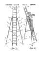
- FIG. 1 is a front elevation view of an extension ladder incorporating the stabilizing leg assembly of the present invention
- FIG. 2 is a perspective view of the apparatus of FIG. 1;
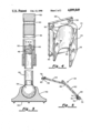
- FIG. 3 is a detailed cross-sectional view of a ladder stabilizing leg in accordance with the present invention.
- FIG. 4 is a drawing of the hinge block
- FIG. 5 is a detailed drawing of the folding brace used in the system of FIG. 1.
- an extension ladder assembly incorporating the stabilizing apparatus of the present invention.
- the extension ladder itself comprises a first, lower section 12 and a second, upper section 14, it being understood that additional ladder extension sections may be added.
- the invention may be applied only to a single ladder section such as section 12 alone.
- Each ladder section includes a pair of side rails 16-18 which are maintained in a predetermined space relationship from one another by a series of transversely extending rungs 20.
- the extension ladder itself is altogether conventional and includes the usual rope and pulley arrangement for raising and lowering the extension sections 14 relative to the base ladder section 12. That rope and pulley arrangement is not illustrated in FIG. 1 in order to eliminate needless lines.
- the ladder sections may be fabricated from a variety of materials including wood, aluminum and aluminum alloys.
- a hinge block 20 attached proximate the upper end of the ladder section 12 is a hinge block 20, the detailed configuration of which is best seen in perspective view of FIG. 4.
- it is seen to include a generally planar surface 22 having an integrally formed U-shaped channel 24 projecting outwardly from the surface 22 at a predetermined acute angle lying in the range of from 30° to 60°. It is found that an angle of 45° is preferred.
- Formed through the outwardly projecting side surfaces of the U-shaped channel are circular apertures 26 and 28 which are horizontally aligned.
- the bracket 20 may readily be fastened to the opposed side rails 16 and 18 of the ladder section by bolts, as at 28 (FIG. 2), passing through the drilled apertures 30 formed in the planar surface of the bracket 20 and through mating apertures formed through the side rails of the ladder.
- first and second elongated, telescopingly extendable tubular pole members 32 and 34 Fitted into the U-shaped channel of each of the brackets are first and second elongated, telescopingly extendable tubular pole members 32 and 34, the constructional details of which may best be seen in the cross-sectional view of FIG. 3.
- the poles each comprises and upper larger diameter tube 36 having a solid, reinforcing plug 38 fitted into the upper end thereof and transversely drilled at 40 for receiving a hinge pin 42 (FIG. 1) passing through the aligned apertures 26 and 28 of the hinge blocks 20.
- a second tube 44 of a lesser diameter Telescopingly receiving within the central portion of the tube 36 is a second tube 44 of a lesser diameter so that it is free to move reciprocally within the central opening of the tubular leg segment 36.
- a plug member 46 is press-fit into the upper end of the lower tubular member 44 and a pin 48 passes through a bore in the plug 46 that is offset from the center of the plug by a distance, e.
- the pin 48 also is made to pass through the center of a circular cam 50 and thus the distance, e, comprises the eccentricity of the cam.
- footpads 52 which are fastened by a ball swivel connection 54 to the lowermost end of the lower tubular segment 44.
- the planar undersurface 56 of the pad 52 can be brought into intimate contact with either smooth or irregular terrain when the stabilizing leg assemblies 32 and 34 are splayed laterally outward and forward of the base of the ladder 12.
- FIG. 5 is a more detailed view of the folding brace member itself. With reference to that figure, it is seen to comprise an extruded metal or plastic channel 62 and a rigid bar 64 which are hinged together by a hinge pin 66 passing through aligned apertures in the members 62 and 64, respectively.
- the other end of the channel 62 is pivotally secured to an outwardly projecting ear 68 which is integrally formed with a clamping collar 70 designed to fit around the circumference of the tubular segment 36 and held tight by a bolt passing through a bore 72 and into a mating threaded bore not shown on the ear 74 on the opposite side of the gap 76 from the bore 72.
- the other end of the bar 64 is likewise pivotally coupled to the ladder side rails 16 and 18 by a bracket 78 which is fastened to the ladder and which has an outwardly projecting ear 80 extending at a predetermined angle for forming a clevis connection with the bar 64 when a pin 82 is passed through aligned apertures in the bar and the ear 80 of the bracket.
- the folding brace members 58 and 60 can only fold through a 180° angle.
- the stabilizing leg assemblies 32 and 34 can be made to collapse against the ladder rails 16 and 18 and can be fastened thereto by a BungeeTM cord or some other type of suitable clamp when being transported or stored.
- the stabilizing legs are swung out to the limit allowed by the folding braces 58 and 60 and because of the construction of the hinge 20, the pads 52 will be splayed laterally outward from the ladder's feet as shown in FIG. 1 and forward of the ladder's feet as illustrated in FIG. 2.
- the length of the stabilizing legs 32 and 34 are readily adjusted by appropriately rotating the lower leg segments 44 until the cam lock 50 releases and then sliding the tubular pole segments 44 upward or downward relative to the leg segments 36. Then, by again rotating the lower leg portions, the eccentric cam lock 50 comes into play to tightly join and lock the two legged segments to one another, preventing sliding of the lower segment relative to the upper.
- the stabilizing legs of the present invention greatly resists any tendency for the ladders to tip to the side even when the individual climbing the ladder is leaning a considerable distance to the side when performing work. Moreover, because the leg assemblies also swing forward relative to the ladder rails, it also inhibits any tendency for the base of the ladder to shift to the rear and greatly insures that the ladder will be inclined at an appropriate angle to resist such slippage before the user ascends same.
Abstract
Description
Claims (8)
Priority Applications (6)
| Application Number | Priority Date | Filing Date | Title |
|---|---|---|---|
| US07/280,124 US4899849A (en) | 1988-12-05 | 1988-12-05 | Ladder stabilizer |
| CA002004466A CA2004466A1 (en) | 1988-12-05 | 1989-12-01 | Ladder stabilizer |
| AR89315603A AR244847A1 (en) | 1988-12-05 | 1989-12-04 | Ladder stabilizer |
| BR898906155A BR8906155A (en) | 1988-12-05 | 1989-12-04 | STAIRS STABILIZER |
| EP89312646A EP0372897A1 (en) | 1988-12-05 | 1989-12-05 | Ladder Stabilizer |
| AU45909/89A AU4590989A (en) | 1988-12-05 | 1989-12-05 | Ladder stabilizer |
Applications Claiming Priority (1)
| Application Number | Priority Date | Filing Date | Title |
|---|---|---|---|
| US07/280,124 US4899849A (en) | 1988-12-05 | 1988-12-05 | Ladder stabilizer |
Publications (1)
| Publication Number | Publication Date |
|---|---|
| US4899849A true US4899849A (en) | 1990-02-13 |
Family
ID=23071787
Family Applications (1)
| Application Number | Title | Priority Date | Filing Date |
|---|---|---|---|
| US07/280,124 Expired - Lifetime US4899849A (en) | 1988-12-05 | 1988-12-05 | Ladder stabilizer |
Country Status (6)
| Country | Link |
|---|---|
| US (1) | US4899849A (en) |
| EP (1) | EP0372897A1 (en) |
| AR (1) | AR244847A1 (en) |
| AU (1) | AU4590989A (en) |
| BR (1) | BR8906155A (en) |
| CA (1) | CA2004466A1 (en) |
Cited By (47)
| Publication number | Priority date | Publication date | Assignee | Title |
|---|---|---|---|---|
| US4949809A (en) * | 1989-12-07 | 1990-08-21 | A. C. Innovations, Inc. | Extendable pole locking mechanism for ladder stabilizer |
| US5086876A (en) * | 1991-04-26 | 1992-02-11 | Severson Gary E | Foot actuated ladder brace |
| US5462133A (en) * | 1994-10-20 | 1995-10-31 | Merrill, Jr.; Warren R. | Step ladder stabilizer |
| US5868222A (en) * | 1994-10-19 | 1999-02-09 | Charbonneau; Francois | Ladder stabilizers |
| GB2329414A (en) * | 1997-08-23 | 1999-03-24 | Iain Hume | Ladder stabilising arrangement |
| US6065566A (en) * | 1998-12-17 | 2000-05-23 | Brown; Michael J. | Ladder safety brace |
| GB2351759A (en) * | 1999-07-05 | 2001-01-10 | A Hines | Door security device |
| US6206139B1 (en) | 1996-10-17 | 2001-03-27 | Robert C. Bogart, Jr. | Folding tripod ladder having extendable legs |
| US6527084B2 (en) | 2000-11-16 | 2003-03-04 | Viorel Hrincu | Ladder stabilizer |
| US6533071B1 (en) | 2000-12-29 | 2003-03-18 | Winston Smith | Ladder with incorporated stabilizers |
| US6672427B1 (en) * | 1999-03-27 | 2004-01-06 | Sandpiper Construction Limited | Ladder base stabiliser |
| US6799660B1 (en) * | 2002-12-26 | 2004-10-05 | James R. Crawford | Step ladder device |
| US20050139425A1 (en) * | 2003-12-04 | 2005-06-30 | Thomas Merle A. | Ladder stabilizer |
| US6959785B1 (en) | 2003-10-24 | 2005-11-01 | Chilton Wade J | Stabilizing system for ladders and scaffolding |
| US20060054398A1 (en) * | 2004-08-27 | 2006-03-16 | Swann Jeffrey J | Ladder stabilizer |
| US20060086570A1 (en) * | 2002-10-15 | 2006-04-27 | Wollenberg Skye L | Ladder stabilizer attachment apparatus and methods |
| US20070251763A1 (en) * | 2006-04-24 | 2007-11-01 | Stephen Pleadwell | Ladder stabilizer |
| US7293630B1 (en) * | 2006-05-10 | 2007-11-13 | Frank Trebec | Ladder stabilization device |
| GB2438071A (en) * | 2006-05-11 | 2007-11-14 | Burton Wire & Tube Company Ltd | Ladder stabilising device |
| US20080011549A1 (en) * | 2006-07-14 | 2008-01-17 | Chris Lott | System for erecting ladder stand for hunting |
| US20080314765A1 (en) * | 2007-06-21 | 2008-12-25 | Commissariat A L'energie Atomique | Method for detecting defective electrodes in a micro-electrode matrix |
| US20090045013A1 (en) * | 2007-08-08 | 2009-02-19 | Mcmurray Daniel | Ladder stabilizer |
| US20090107765A1 (en) * | 2007-10-30 | 2009-04-30 | Clyde Germond | Extension ladder stabilizer |
| US20090314579A1 (en) * | 2008-06-18 | 2009-12-24 | Allan Withers | Ladder stabilizer |
| US20100252364A1 (en) * | 2009-04-03 | 2010-10-07 | Vestal Floyd Lavern | Collapsible safe ladder |
| US20110017549A1 (en) * | 2009-07-27 | 2011-01-27 | Lietz James D | Stabilizer kit for providing reinforcing support to a ladder |
| US20110017548A1 (en) * | 2009-04-03 | 2011-01-27 | Jeffrey Green | Collapsible safe ladder |
| US20110067954A1 (en) * | 2005-10-20 | 2011-03-24 | Clifton Deal | Ladder Safety Device |
| US20110147121A1 (en) * | 2009-12-18 | 2011-06-23 | Michael David Potter | Ladder Stabilizing Device |
| US20120168253A1 (en) * | 2008-08-07 | 2012-07-05 | Mcmurray Daniel | Ladder stabilizer |
| USD668789S1 (en) | 2009-04-03 | 2012-10-09 | Lock N Climb, Llc | Support rail for a ladder |
| US20130270037A1 (en) * | 2010-12-21 | 2013-10-17 | Roberto Giuseppe Pensieri | Ladder with enhanced stability |
| US8602162B2 (en) | 2011-04-18 | 2013-12-10 | King Fahd University Of Petroleum And Minerals | Safety ladder |
| US9187954B1 (en) * | 2009-01-26 | 2015-11-17 | Andrew S. Parsons | Angle configuring stabilizing assembly for extension ladders |
| USD745191S1 (en) | 2014-05-27 | 2015-12-08 | Lock N Climb, Llc | Ladder |
| USD757959S1 (en) * | 2015-04-28 | 2016-05-31 | Tokuo AOI | Stepladder |
| USD758615S1 (en) * | 2015-04-28 | 2016-06-07 | Tokuo AOI | Stepladder |
| USD761442S1 (en) * | 2014-07-10 | 2016-07-12 | Tokuo AOI | Stepladder |
| USD765269S1 (en) | 2015-04-28 | 2016-08-30 | Tokuo AOI | Stepladder |
| US9534443B1 (en) | 2011-12-27 | 2017-01-03 | Robert C. Bogart | Ladder and related methods |
| US9689204B2 (en) | 2013-02-26 | 2017-06-27 | Tokuo AOI | Stepladder |
| US20180340371A1 (en) * | 2017-05-26 | 2018-11-29 | John Georges | Ladder support system and method |
| US20190048661A1 (en) * | 2016-11-25 | 2019-02-14 | Kumprey Llc | A ladder support device and a method for securing a ladder to a base |
| US10519716B2 (en) | 2016-05-18 | 2019-12-31 | George Saxby | Ladder support attachment |
| WO2021081356A1 (en) * | 2019-10-24 | 2021-04-29 | Core Distribution, Inc. | Ladder tripod assembly and system |
| CN115450553A (en) * | 2022-09-29 | 2022-12-09 | 共享装备股份有限公司 | Ladder anti-shaking device and ladder |
| US20230228150A1 (en) * | 2022-01-18 | 2023-07-20 | Charles J. Mackarvich | Modular ladder system |
Families Citing this family (7)
| Publication number | Priority date | Publication date | Assignee | Title |
|---|---|---|---|---|
| DE19701497A1 (en) * | 1997-01-17 | 1997-07-03 | Horst Laug | Folding and telescopic supporting outrigger for ladder |
| GB9715959D0 (en) * | 1997-07-30 | 1997-10-01 | Stephens Raymond L | Improvements relating to ladder stabilising device |
| DE10113477C2 (en) * | 2001-02-02 | 2003-12-24 | Portheine Hein | Stabilization support with integrated spread protection |
| DE502004006945D1 (en) * | 2003-07-18 | 2008-06-05 | Ursula Bichsel | LADDER WITH SAFETY DEVICE |
| CA2544358A1 (en) * | 2003-10-31 | 2005-05-12 | Wing Enterprises, Inc. | Adjustable stepladders and related methods |
| EP1711678A1 (en) * | 2004-02-07 | 2006-10-18 | Sandpiper Construction Limited | Ladder stabiliser |
| AT16594U1 (en) * | 2018-09-05 | 2020-02-15 | Kastenhuber Wolfgang | Telescopic spreaders for step ladders and leaning ladders |
Citations (12)
| Publication number | Priority date | Publication date | Assignee | Title |
|---|---|---|---|---|
| US46105A (en) * | 1865-01-31 | Improved orchard-ladder | ||
| US485900A (en) * | 1892-11-08 | August otto tannenberg | ||
| US1135763A (en) * | 1914-03-17 | 1915-04-13 | Frank Joseph Caronia | Step-ladder. |
| US1235696A (en) * | 1916-08-21 | 1917-08-07 | Boyd B Keith | Step-ladder. |
| US1526654A (en) * | 1923-02-01 | 1925-02-17 | Yordy Amos | Stepladder |
| US1910551A (en) * | 1930-11-11 | 1933-05-23 | Ernst J Kruse | Orchard ladder safety device |
| US2149781A (en) * | 1937-11-02 | 1939-03-07 | Dorothy R Atler | Safety device for ladders |
| US2997127A (en) * | 1959-10-07 | 1961-08-22 | Wojtowicz Michael | Stepladder with improved stabilizing legs |
| FR1467900A (en) * | 1965-12-20 | 1967-02-03 | Ladder safety device | |
| US3878917A (en) * | 1973-07-16 | 1975-04-22 | Leo Robert Mcbride | Adjustable ladder support attachment |
| US3901354A (en) * | 1974-07-05 | 1975-08-26 | Alex J Grebausky | Stepladder stabilizer |
| US4433754A (en) * | 1981-11-13 | 1984-02-28 | John Beach | Stepladder stabilizer assembly |
Family Cites Families (4)
| Publication number | Priority date | Publication date | Assignee | Title |
|---|---|---|---|---|
| US4324502A (en) * | 1979-12-31 | 1982-04-13 | Texaco, Inc. | Locking mechanism for telescopic tubing |
| GB2180875B (en) * | 1985-09-26 | 1988-11-23 | Richard Henry Young | A structure for stabilising a ladder |
| GB2190419A (en) * | 1986-05-16 | 1987-11-18 | Arthur Albert Gould | Step ladders |
| DE8700350U1 (en) * | 1987-01-08 | 1987-03-05 | Meier, Alexander, 4763 Ense, De |
-
1988
- 1988-12-05 US US07/280,124 patent/US4899849A/en not_active Expired - Lifetime
-
1989
- 1989-12-01 CA CA002004466A patent/CA2004466A1/en not_active Abandoned
- 1989-12-04 BR BR898906155A patent/BR8906155A/en unknown
- 1989-12-04 AR AR89315603A patent/AR244847A1/en active
- 1989-12-05 AU AU45909/89A patent/AU4590989A/en not_active Abandoned
- 1989-12-05 EP EP89312646A patent/EP0372897A1/en not_active Withdrawn
Patent Citations (12)
| Publication number | Priority date | Publication date | Assignee | Title |
|---|---|---|---|---|
| US46105A (en) * | 1865-01-31 | Improved orchard-ladder | ||
| US485900A (en) * | 1892-11-08 | August otto tannenberg | ||
| US1135763A (en) * | 1914-03-17 | 1915-04-13 | Frank Joseph Caronia | Step-ladder. |
| US1235696A (en) * | 1916-08-21 | 1917-08-07 | Boyd B Keith | Step-ladder. |
| US1526654A (en) * | 1923-02-01 | 1925-02-17 | Yordy Amos | Stepladder |
| US1910551A (en) * | 1930-11-11 | 1933-05-23 | Ernst J Kruse | Orchard ladder safety device |
| US2149781A (en) * | 1937-11-02 | 1939-03-07 | Dorothy R Atler | Safety device for ladders |
| US2997127A (en) * | 1959-10-07 | 1961-08-22 | Wojtowicz Michael | Stepladder with improved stabilizing legs |
| FR1467900A (en) * | 1965-12-20 | 1967-02-03 | Ladder safety device | |
| US3878917A (en) * | 1973-07-16 | 1975-04-22 | Leo Robert Mcbride | Adjustable ladder support attachment |
| US3901354A (en) * | 1974-07-05 | 1975-08-26 | Alex J Grebausky | Stepladder stabilizer |
| US4433754A (en) * | 1981-11-13 | 1984-02-28 | John Beach | Stepladder stabilizer assembly |
Cited By (61)
| Publication number | Priority date | Publication date | Assignee | Title |
|---|---|---|---|---|
| US4949809A (en) * | 1989-12-07 | 1990-08-21 | A. C. Innovations, Inc. | Extendable pole locking mechanism for ladder stabilizer |
| US5086876A (en) * | 1991-04-26 | 1992-02-11 | Severson Gary E | Foot actuated ladder brace |
| US5868222A (en) * | 1994-10-19 | 1999-02-09 | Charbonneau; Francois | Ladder stabilizers |
| US5462133A (en) * | 1994-10-20 | 1995-10-31 | Merrill, Jr.; Warren R. | Step ladder stabilizer |
| US6206139B1 (en) | 1996-10-17 | 2001-03-27 | Robert C. Bogart, Jr. | Folding tripod ladder having extendable legs |
| GB2329414A (en) * | 1997-08-23 | 1999-03-24 | Iain Hume | Ladder stabilising arrangement |
| US6065566A (en) * | 1998-12-17 | 2000-05-23 | Brown; Michael J. | Ladder safety brace |
| US6672427B1 (en) * | 1999-03-27 | 2004-01-06 | Sandpiper Construction Limited | Ladder base stabiliser |
| GB2351759A (en) * | 1999-07-05 | 2001-01-10 | A Hines | Door security device |
| US6527084B2 (en) | 2000-11-16 | 2003-03-04 | Viorel Hrincu | Ladder stabilizer |
| US6533071B1 (en) | 2000-12-29 | 2003-03-18 | Winston Smith | Ladder with incorporated stabilizers |
| US7789199B2 (en) * | 2002-10-15 | 2010-09-07 | Trade Associates, Inc. | Ladder stabilizer attachment apparatus and methods |
| US20060086570A1 (en) * | 2002-10-15 | 2006-04-27 | Wollenberg Skye L | Ladder stabilizer attachment apparatus and methods |
| US6799660B1 (en) * | 2002-12-26 | 2004-10-05 | James R. Crawford | Step ladder device |
| US6959785B1 (en) | 2003-10-24 | 2005-11-01 | Chilton Wade J | Stabilizing system for ladders and scaffolding |
| US20050139425A1 (en) * | 2003-12-04 | 2005-06-30 | Thomas Merle A. | Ladder stabilizer |
| US7093690B2 (en) | 2004-08-27 | 2006-08-22 | Swann Jeffrey J | Ladder stabilizer |
| US20060054398A1 (en) * | 2004-08-27 | 2006-03-16 | Swann Jeffrey J | Ladder stabilizer |
| US20110067954A1 (en) * | 2005-10-20 | 2011-03-24 | Clifton Deal | Ladder Safety Device |
| US7757814B2 (en) | 2006-04-24 | 2010-07-20 | Ladder Stabilizerz Inc. | Ladder stabilizer |
| US20070251763A1 (en) * | 2006-04-24 | 2007-11-01 | Stephen Pleadwell | Ladder stabilizer |
| US7293630B1 (en) * | 2006-05-10 | 2007-11-13 | Frank Trebec | Ladder stabilization device |
| US20070261918A1 (en) * | 2006-05-10 | 2007-11-15 | Frank Trebec | Ladder stabilization device |
| GB2438071A (en) * | 2006-05-11 | 2007-11-14 | Burton Wire & Tube Company Ltd | Ladder stabilising device |
| US20080011549A1 (en) * | 2006-07-14 | 2008-01-17 | Chris Lott | System for erecting ladder stand for hunting |
| US20080314765A1 (en) * | 2007-06-21 | 2008-12-25 | Commissariat A L'energie Atomique | Method for detecting defective electrodes in a micro-electrode matrix |
| US20090045013A1 (en) * | 2007-08-08 | 2009-02-19 | Mcmurray Daniel | Ladder stabilizer |
| WO2009058161A1 (en) * | 2007-10-30 | 2009-05-07 | Clyde Germond | Extension ladder stabilizer |
| US20090107765A1 (en) * | 2007-10-30 | 2009-04-30 | Clyde Germond | Extension ladder stabilizer |
| US20090314579A1 (en) * | 2008-06-18 | 2009-12-24 | Allan Withers | Ladder stabilizer |
| US20120168253A1 (en) * | 2008-08-07 | 2012-07-05 | Mcmurray Daniel | Ladder stabilizer |
| US9187954B1 (en) * | 2009-01-26 | 2015-11-17 | Andrew S. Parsons | Angle configuring stabilizing assembly for extension ladders |
| US20110017548A1 (en) * | 2009-04-03 | 2011-01-27 | Jeffrey Green | Collapsible safe ladder |
| US8485316B2 (en) * | 2009-04-03 | 2013-07-16 | Lock N Climb, Llc | Collapsible safe ladder |
| US20100252364A1 (en) * | 2009-04-03 | 2010-10-07 | Vestal Floyd Lavern | Collapsible safe ladder |
| USD668789S1 (en) | 2009-04-03 | 2012-10-09 | Lock N Climb, Llc | Support rail for a ladder |
| US9038776B2 (en) | 2009-04-03 | 2015-05-26 | Lock N Climb, Llc | Collapsible safe ladder |
| US8424642B2 (en) | 2009-07-27 | 2013-04-23 | James D. Lietz | Stabilizer kit for providing reinforcing support to a ladder |
| US20110017549A1 (en) * | 2009-07-27 | 2011-01-27 | Lietz James D | Stabilizer kit for providing reinforcing support to a ladder |
| US8590671B2 (en) * | 2009-12-18 | 2013-11-26 | Michael David Potter | Ladder stabilizing device |
| US20110147121A1 (en) * | 2009-12-18 | 2011-06-23 | Michael David Potter | Ladder Stabilizing Device |
| US20130270037A1 (en) * | 2010-12-21 | 2013-10-17 | Roberto Giuseppe Pensieri | Ladder with enhanced stability |
| US8602162B2 (en) | 2011-04-18 | 2013-12-10 | King Fahd University Of Petroleum And Minerals | Safety ladder |
| US9534443B1 (en) | 2011-12-27 | 2017-01-03 | Robert C. Bogart | Ladder and related methods |
| US9689204B2 (en) | 2013-02-26 | 2017-06-27 | Tokuo AOI | Stepladder |
| USD745191S1 (en) | 2014-05-27 | 2015-12-08 | Lock N Climb, Llc | Ladder |
| USD761442S1 (en) * | 2014-07-10 | 2016-07-12 | Tokuo AOI | Stepladder |
| USD765269S1 (en) | 2015-04-28 | 2016-08-30 | Tokuo AOI | Stepladder |
| USD758615S1 (en) * | 2015-04-28 | 2016-06-07 | Tokuo AOI | Stepladder |
| USD757959S1 (en) * | 2015-04-28 | 2016-05-31 | Tokuo AOI | Stepladder |
| US10519716B2 (en) | 2016-05-18 | 2019-12-31 | George Saxby | Ladder support attachment |
| US20190048661A1 (en) * | 2016-11-25 | 2019-02-14 | Kumprey Llc | A ladder support device and a method for securing a ladder to a base |
| US20180340371A1 (en) * | 2017-05-26 | 2018-11-29 | John Georges | Ladder support system and method |
| US20210123302A1 (en) * | 2019-10-24 | 2021-04-29 | Core Distribution, Inc. | Ladder tripod assembly and system |
| WO2021081356A1 (en) * | 2019-10-24 | 2021-04-29 | Core Distribution, Inc. | Ladder tripod assembly and system |
| US11795760B2 (en) * | 2019-10-24 | 2023-10-24 | Core Distribution, Inc. | Ladder tripod assembly and system |
| EP4269744A3 (en) * | 2019-10-24 | 2023-12-06 | Core Distribution, Inc. | Ladder tripod assembly and system |
| US20230228150A1 (en) * | 2022-01-18 | 2023-07-20 | Charles J. Mackarvich | Modular ladder system |
| US11885180B2 (en) * | 2022-01-18 | 2024-01-30 | Charles J. Mackarvich | Modular ladder system |
| CN115450553A (en) * | 2022-09-29 | 2022-12-09 | 共享装备股份有限公司 | Ladder anti-shaking device and ladder |
| CN115450553B (en) * | 2022-09-29 | 2023-12-29 | 共享装备股份有限公司 | Ladder anti-shaking device and ladder |
Also Published As
| Publication number | Publication date |
|---|---|
| CA2004466A1 (en) | 1990-06-05 |
| AR244847A1 (en) | 1993-11-30 |
| AU4590989A (en) | 1990-06-07 |
| BR8906155A (en) | 1990-07-31 |
| EP0372897A1 (en) | 1990-06-13 |
Similar Documents
| Publication | Publication Date | Title |
|---|---|---|
| US4899849A (en) | Ladder stabilizer | |
| US5868222A (en) | Ladder stabilizers | |
| US4949809A (en) | Extendable pole locking mechanism for ladder stabilizer | |
| US6382353B2 (en) | Slip prevention device for ladders | |
| US4742888A (en) | Folding ladder stand | |
| US6527084B2 (en) | Ladder stabilizer | |
| US20100213007A1 (en) | Ladder system | |
| US5857544A (en) | Independent mobile work ladder support stand | |
| US5918698A (en) | Safety support apparatus for ladders | |
| CA2028748A1 (en) | Tree stand with telescoping seat | |
| US6357548B1 (en) | Ladder support device | |
| US20100230208A1 (en) | Convertible multipurpose ladder stabilizers | |
| US3568798A (en) | Ladder stabilizer | |
| US7255198B1 (en) | Tripod extension stepladder | |
| US20180340371A1 (en) | Ladder support system and method | |
| US20150191975A1 (en) | Vehicle Hitch Ladder Support Device | |
| US7093690B2 (en) | Ladder stabilizer | |
| US8424643B1 (en) | Boat work platform | |
| US5076547A (en) | Apparatus and method for collapsible handrail | |
| US3637046A (en) | Foldable ladder | |
| US5967261A (en) | Stair-ladder platform | |
| JPH1088950A (en) | Attachment for ladder | |
| GB2158498A (en) | Ladder attachment | |
| WO2020169942A1 (en) | Improved step ladder and support structure | |
| CA2305199A1 (en) | Laterally assisting platform support |
Legal Events
| Date | Code | Title | Description |
|---|---|---|---|
| AS | Assignment |
Owner name: A.C. INNOVATIONS, INC., A CORP. OF MN, MINNESOTA Free format text: ASSIGNMENT OF ASSIGNORS INTEREST.;ASSIGNORS:LEVI, AVRAHAM Y.;QUARBERG, CRAIG D.;REEL/FRAME:005031/0342 Effective date: 19890222 |
|
| AS | Assignment |
Owner name: REPUBLIC ACCEPTANCE CORPORATION, INC. Free format text: SECURITY INTEREST;ASSIGNOR:A.C. INNOVATIONS, INC., A CORP. OF MINNESOTA;REEL/FRAME:005554/0774 Effective date: 19900412 |
|
| AS | Assignment |
Owner name: A. C. INNOVATIONS, INC. Free format text: RELEASE BY SECURED PARTY OF SECURITY AGREEMENTS RECORDED AT REEL 5554 FRAME 0774 AND REEL 5554 FRAME 0671;ASSIGNOR:REPUBLIC ACCEPTANCE CORPORATION A CORP. OF MINNESOTA;REEL/FRAME:006040/0186 Effective date: 19920224 Owner name: REPUBLIC ACCEPTANCE CORPORATION, MINNESOTA Free format text: SECURITY INTEREST;ASSIGNOR:J. M. EINI U.S.A., INC.;REEL/FRAME:006040/0175 Effective date: 19911218 Owner name: J. M. EINI U.S.A., INC. Free format text: ASSIGNMENT OF ASSIGNORS INTEREST.;ASSIGNOR:A. C. INNOVATIONS, INC.;REEL/FRAME:006040/0170 Effective date: 19911114 |
|
| AS | Assignment |
Owner name: NEW RAC CORP., MINNESOTA Free format text: ASSIGNMENT OF ASSIGNORS INTEREST;ASSIGNOR:REPUBLIC ACCEPTANCE CORPORATION;REEL/FRAME:006611/0879 Effective date: 19930628 |
|
| AS | Assignment |
Owner name: REPUBLIC ACCEPTANCE CORPORATION, MINNESOTA Free format text: CHANGE OF NAME;ASSIGNOR:NEW RAC CORP.;REEL/FRAME:006615/0147 Effective date: 19930628 |
|
| REMI | Maintenance fee reminder mailed | ||
| FEPP | Fee payment procedure |
Free format text: PETITION RELATED TO MAINTENANCE FEES GRANTED (ORIGINAL EVENT CODE: PMFG); ENTITY STATUS OF PATENT OWNER: LARGE ENTITY Free format text: PAT HLDR NO LONGER CLAIMS SMALL ENT STAT AS INDIV INVENTOR (ORIGINAL EVENT CODE: LSM1); ENTITY STATUS OF PATENT OWNER: LARGE ENTITY |
|
| REIN | Reinstatement after maintenance fee payment confirmed | ||
| FPAY | Fee payment |
Year of fee payment: 4 |
|
| SULP | Surcharge for late payment | ||
| FP | Lapsed due to failure to pay maintenance fee |
Effective date: 19940213 |
|
| STCF | Information on status: patent grant |
Free format text: PATENTED CASE |
|
| AS | Assignment |
Owner name: REPUBLIC ACCEPTANCE CORPORATION, MINNESOTA Free format text: COURT ORDER;ASSIGNOR:J. M. EINI U.S.A., INC.;REEL/FRAME:007052/0854 Effective date: 19930112 |
|
| DP | Notification of acceptance of delayed payment of maintenance fee |