US4899709A - Electric controlling element for the power-setting element of an internal combustion engine - Google Patents

Electric controlling element for the power-setting element of an internal combustion engine Download PDF

Info

Publication number
US4899709A
US4899709A US07/306,885 US30688589A US4899709A US 4899709 A US4899709 A US 4899709A US 30688589 A US30688589 A US 30688589A US 4899709 A US4899709 A US 4899709A
Authority
US
United States
Prior art keywords
controlling element
electromagnet
armature
clutch
electric controlling
Prior art date
Legal status (The legal status is an assumption and is not a legal conclusion. Google has not performed a legal analysis and makes no representation as to the accuracy of the status listed.)
Expired - Fee Related
Application number
US07/306,885
Inventor
Rudolf Aufmkolk
Current Assignee (The listed assignees may be inaccurate. Google has not performed a legal analysis and makes no representation or warranty as to the accuracy of the list.)
Mannesmann VDO AG
Original Assignee
Mannesmann VDO AG
Priority date (The priority date is an assumption and is not a legal conclusion. Google has not performed a legal analysis and makes no representation as to the accuracy of the date listed.)
Filing date
Publication date
Application filed by Mannesmann VDO AG filed Critical Mannesmann VDO AG
Assigned to VDO ADOLF SCHINDLING AG reassignment VDO ADOLF SCHINDLING AG ASSIGNMENT OF ASSIGNORS INTEREST. Assignors: AUFMKOLK, RUDOLF
Application granted granted Critical
Publication of US4899709A publication Critical patent/US4899709A/en
Anticipated expiration legal-status Critical
Expired - Fee Related legal-status Critical Current

Links

Images

Classifications

    • FMECHANICAL ENGINEERING; LIGHTING; HEATING; WEAPONS; BLASTING
    • F02COMBUSTION ENGINES; HOT-GAS OR COMBUSTION-PRODUCT ENGINE PLANTS
    • F02DCONTROLLING COMBUSTION ENGINES
    • F02D11/00Arrangements for, or adaptations to, non-automatic engine control initiation means, e.g. operator initiated
    • F02D11/06Arrangements for, or adaptations to, non-automatic engine control initiation means, e.g. operator initiated characterised by non-mechanical control linkages, e.g. fluid control linkages or by control linkages with power drive or assistance
    • F02D11/10Arrangements for, or adaptations to, non-automatic engine control initiation means, e.g. operator initiated characterised by non-mechanical control linkages, e.g. fluid control linkages or by control linkages with power drive or assistance of the electric type
    • F02D2011/101Arrangements for, or adaptations to, non-automatic engine control initiation means, e.g. operator initiated characterised by non-mechanical control linkages, e.g. fluid control linkages or by control linkages with power drive or assistance of the electric type characterised by the means for actuating the throttles
    • F02D2011/103Arrangements for, or adaptations to, non-automatic engine control initiation means, e.g. operator initiated characterised by non-mechanical control linkages, e.g. fluid control linkages or by control linkages with power drive or assistance of the electric type characterised by the means for actuating the throttles at least one throttle being alternatively mechanically linked to the pedal or moved by an electric actuator

Definitions

  • the present invention relates to an electric controlling element for the power-setting element of an internal combustion engine in which the controlling element operates a power setting element such as a throttle valve, the controlling element including a drive device and a clutch having an electromagnet arranged between the drive device and the power-setting element and wherein, upon passage of current to said electromagnet, an armature is attracted against the force of a spring, the clutch being thereby closed.
  • a power setting element such as a throttle valve
  • Such known controlling elements are used in systems for regulating the speed of motor vehicles, the vehicle maintaining a preselected speed by automatic displacement of the power-setting element, for instance the throttle valve. Furthermore, such controlling elements can also be used to control the speed of the vehicle, the position of the gas pedal being transmitted electrically to the power-setting element (so-called E-gas systems).
  • a drive device which consists of an electric motor, a gearing and a spindle drive and moves a plunger magnet linearly.
  • the plunger magnet cooperates with an armature plate which is connected, as clutch, via a pull cable to the throttle valve.
  • the clutch which consists of the plunger magnet and the armature plate is closed, so that the linear movement produced by rotation of the spindle is transmitted to the pull cable and thus to the throttle valve. This movement takes place in opposition to the force of a return spring which seeks to pull the throttle valve into the idling position.
  • the clutch formed by the plunger magnet and the armature plate has the task of maintaining the force lock between the drive device and the throttle valve under normal operation but to disconnect rapidly the drive device from the throttle valve if the vehicle brake or clutch is actuated.
  • the current is disconnected from the winding of the plunger magnet so that the return spring can move the throttle valve into its idling position.
  • the clutch is furthermore opened in the event of an error in the control or regulating system or if, for instance, the operating voltage fails.
  • limit switches are provided which are actuated when the plunger magnet reaches its end positions. In this way, the drive device can be disconnected when the end positions are reached.
  • the known controlling element it may happen that when the clutch is open, the current is again connected through the winding of the plunger magnet and, upon a corresponding movement of the gas pedal or corresponding control by the speed governor system, the plunger magnet approaches the armature plate and attracts it, as a result of which the throttle valve is suddenly opened. This, in its turn, can lead to a dangerous situation.
  • a switch (e.g. 5) is provided which can be actuated as a function of the distance between the electromagnet (3) and the armature (7).
  • Another advantage of the electric controlling element in accordance with the invention is that, by means of the switch, the opening of the clutch can be reported to the control device. Such unintended opening takes place, for instance, if, due to a defect, the throttle valve, the pull cable or the armature plate becomes jammed, and the drive device controls the plunger magnet in the direction towards the opening of the throttle valve and thus forcefully opens the clutch. In this case, the corresponding report of a disturbance is produced by the actuating of the switch.
  • the drive device (1, 2) produces a linear movement.
  • the drive device (1, 2) comprises an electric motor, a gearing and a spindle.
  • the electromagnet is developed as a plunger magnet (3) and the armature as an armature plate (7), the switch (5) being arranged in the plunger magnet (3).
  • the switch (5) is conductive when the armature (7) contacts the electromagnet (3).
  • the switch is formed by a reed contact.
  • a particularly simple electrical connection between the switch and the winding of the electromagnet consists, in accordance with one advantageous embodiment of the invention, in that the switch (5) is connected in series with a winding (6) of the electromagnet (3) and a controllable switch (16).
  • Another feature of this embodiment permits in simple manner a report of the position of the switch to a control unit serving for the control in the manner that a first pole (18) of a source of operating voltage can be connected via the controllable switch (16) to a first terminal (17) of the winding (6), that the switch (5) is arranged between the second terminal (18) of the winding (6) and the second pole of the source of operating voltage, and that the second terminal (18) of the winding (6) is connected via a resistor (22) with another source of operating voltage (23) and, preferably via another resistor (24) to an input (25) of a control deice (15), and that a control input of the controllable switch (16) is connected to an output (21) of the control device (15).
  • FIG. 1 is a diagrammatic showing of one embodiment
  • FIG. 2 is a circuit diagram in accordance with a further development of the invention.
  • the arrangement in accordance with FIG. 1 comprises a well-known electromotive drive 1 which comprises a motor and a gearing.
  • the drive 1 operates through a threaded spindle 2.
  • the threaded spindle 2 is in engagement with a plunger magnet 3 which is secured against turning by means of a guide element 4.
  • the plunger magnet 3 is moved in the direction indicated by the arrow.
  • the plunger magnet 3 has a coil 6 which produces a magnetic field when it is traversed by current. By this magnetic field an armature plate 7 can be attracted to the plunger magnet.
  • the armature plate 7 is displaceably mounted and is connected by a pull cable 8 to a throttle valve device 9.
  • the throttle valve device 9 has a return spring 10 which is shown in FIG. 1 for purposes of illustration as acting directly on the armature plate 7.
  • a switch 5 which is closed via a ram 11 when the armature plate 7 is in the direct vicinity of the plunger magnet.
  • switches are suitable as switch 5, for instance those known as microswitches.
  • reed switches which respond suitably to a change in the magnetic field upon attraction of the armature plate 7 are also suitable.
  • Other switches 12, 13 serve in known manner as limit switches.
  • FIG. 1 shows a controlling element for the control or regulating of the engine power, such as used, for instance, in a speed governing system.
  • the electromotive drive 1 is controlled via an output stage 14 (FIG. 2) in the direction of the desired control by a control device 15 which consists essentially of a microcomputer.
  • control devices are known per se and need not be further described in connection with the present invention.
  • the coil 6 is connected via a controllable switch, provided by a transistor 16, to the positive terminal (+UB) of a source of operating voltage (not shown).
  • the transistor 16 is preferably a power transistor. While a first terminal 17 of the winding 6 is connected to the collector of the transistor 16, a second terminal 18 of the winding 8 is connected to ground potential via the switch 5.
  • the base of the transistor 16 is connected via a voltage divider 19, 20 to an output 21 of the control device 15.
  • the terminal 18 of the winding 6 is connected via a so-called pull-up resistor 22 to the positive terminal 23 of a stabilized source of operating voltage (+5V) and, via another resistor 24, to an input 25 of the control device 15.
  • the clutch Upon normal regulating or control operation the clutch is engaged and the switch 5 closed.
  • the terminal 18 then has ground potential.
  • the input 25 of the control device 15 is then also at ground potential. If the brake of the motor vehicle is, for instance, actuated, then the transistor 16 is brought into the non-conductive state by the control device 15 so that the current through the winding 6 and thus the magnetic field are disconnected. Except for the case that the plunger magnet 3 is in the outermost right-hand position, the armature plate 7 is then moved away from the plunger magnet by the spring 10.
  • the switch 5 opens and a level of 5V, which can be evaluated as return-report signal, is present at the input 25 of the microcomputer.
  • the switch is opened and a corresponding signal is fed to the input 25 of the control device 15, which signal is evaluated there as the report of a disturbance.

Abstract

In an electric controlling member for the power-setting element of an internal combustion engine in which a clutch having an electromagnet is arranged between a drive device and the power-setting element of the engine. Upon the passage of current through said electromagnet, an armature is attracted against the force of a spring, the clutch being thereby closed. A switch is provided which can be actuated as a function of the distance between the electromagnet and the armature.

Description

FIELD AND BACKGROUND OF THE INVENTION
The present invention relates to an electric controlling element for the power-setting element of an internal combustion engine in which the controlling element operates a power setting element such as a throttle valve, the controlling element including a drive device and a clutch having an electromagnet arranged between the drive device and the power-setting element and wherein, upon passage of current to said electromagnet, an armature is attracted against the force of a spring, the clutch being thereby closed.
Such known controlling elements are used in systems for regulating the speed of motor vehicles, the vehicle maintaining a preselected speed by automatic displacement of the power-setting element, for instance the throttle valve. Furthermore, such controlling elements can also be used to control the speed of the vehicle, the position of the gas pedal being transmitted electrically to the power-setting element (so-called E-gas systems).
In one known electric controlling element a drive device is provided which consists of an electric motor, a gearing and a spindle drive and moves a plunger magnet linearly. The plunger magnet cooperates with an armature plate which is connected, as clutch, via a pull cable to the throttle valve. In normal operation, the clutch which consists of the plunger magnet and the armature plate is closed, so that the linear movement produced by rotation of the spindle is transmitted to the pull cable and thus to the throttle valve. This movement takes place in opposition to the force of a return spring which seeks to pull the throttle valve into the idling position.
The clutch formed by the plunger magnet and the armature plate has the task of maintaining the force lock between the drive device and the throttle valve under normal operation but to disconnect rapidly the drive device from the throttle valve if the vehicle brake or clutch is actuated. For this purpose, the current is disconnected from the winding of the plunger magnet so that the return spring can move the throttle valve into its idling position. The clutch is furthermore opened in the event of an error in the control or regulating system or if, for instance, the operating voltage fails.
In the known controlling element, limit switches are provided which are actuated when the plunger magnet reaches its end positions. In this way, the drive device can be disconnected when the end positions are reached. In the known controlling element it may happen that when the clutch is open, the current is again connected through the winding of the plunger magnet and, upon a corresponding movement of the gas pedal or corresponding control by the speed governor system, the plunger magnet approaches the armature plate and attracts it, as a result of which the throttle valve is suddenly opened. This, in its turn, can lead to a dangerous situation.
SUMMARY OF THE INVENTION
It is an object of the present invention, therefore, to permit the closing of the clutch only when the plunger magnet is in the idling position.
According to the invention, a switch (e.g. 5) is provided which can be actuated as a function of the distance between the electromagnet (3) and the armature (7).
Due to the fact that the electric circuit of the electromagnet is made dependent in suitable manner on the position of the switch, assurance is had that after an opening of the clutch, the plunger magnet must first be brought towards the armature plate up to the idling position before re-engagement takes place.
Another advantage of the electric controlling element in accordance with the invention is that, by means of the switch, the opening of the clutch can be reported to the control device. Such unintended opening takes place, for instance, if, due to a defect, the throttle valve, the pull cable or the armature plate becomes jammed, and the drive device controls the plunger magnet in the direction towards the opening of the throttle valve and thus forcefully opens the clutch. In this case, the corresponding report of a disturbance is produced by the actuating of the switch.
According to a further feature of the invention, the drive device (1, 2) produces a linear movement.
Another feature is that the drive device (1, 2) comprises an electric motor, a gearing and a spindle.
Further according to the invention, the electromagnet is developed as a plunger magnet (3) and the armature as an armature plate (7), the switch (5) being arranged in the plunger magnet (3).
Also by another feature of the invention, the switch (5) is conductive when the armature (7) contacts the electromagnet (3).
Still further, the switch is formed by a reed contact.
A particularly simple electrical connection between the switch and the winding of the electromagnet consists, in accordance with one advantageous embodiment of the invention, in that the switch (5) is connected in series with a winding (6) of the electromagnet (3) and a controllable switch (16).
Another feature of this embodiment permits in simple manner a report of the position of the switch to a control unit serving for the control in the manner that a first pole (18) of a source of operating voltage can be connected via the controllable switch (16) to a first terminal (17) of the winding (6), that the switch (5) is arranged between the second terminal (18) of the winding (6) and the second pole of the source of operating voltage, and that the second terminal (18) of the winding (6) is connected via a resistor (22) with another source of operating voltage (23) and, preferably via another resistor (24) to an input (25) of a control deice (15), and that a control input of the controllable switch (16) is connected to an output (21) of the control device (15).
BRIEF DESCRIPTION OF THE DRAWING
With the above and other objects and advantages in view, the present invention will become more clearly understood in connection with the detailed description of a preferred embodiment, when considered with the accompanying drawing, of which:
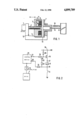
FIG. 1 is a diagrammatic showing of one embodiment; and
FIG. 2 is a circuit diagram in accordance with a further development of the invention.
Identical parts in the figures have been provided with the same reference numbers.
DETAILED DESCRIPTION OF THE PREFERRED EMBODIMENT
The arrangement in accordance with FIG. 1 comprises a well-known electromotive drive 1 which comprises a motor and a gearing. The drive 1 operates through a threaded spindle 2. The threaded spindle 2 is in engagement with a plunger magnet 3 which is secured against turning by means of a guide element 4. By the turning of the threaded spindle 2 the plunger magnet 3 is moved in the direction indicated by the arrow.
The plunger magnet 3 has a coil 6 which produces a magnetic field when it is traversed by current. By this magnetic field an armature plate 7 can be attracted to the plunger magnet. The armature plate 7 is displaceably mounted and is connected by a pull cable 8 to a throttle valve device 9. In known manner, the throttle valve device 9 has a return spring 10 which is shown in FIG. 1 for purposes of illustration as acting directly on the armature plate 7. Within the plunger magnet 3 there is a switch 5 which is closed via a ram 11 when the armature plate 7 is in the direct vicinity of the plunger magnet.
Various embodiments of switches are suitable as switch 5, for instance those known as microswitches. However, reed switches which respond suitably to a change in the magnetic field upon attraction of the armature plate 7 are also suitable. Other switches 12, 13 serve in known manner as limit switches.
The arrangement according to FIG. 1 shows a controlling element for the control or regulating of the engine power, such as used, for instance, in a speed governing system. In this case, the electromotive drive 1 is controlled via an output stage 14 (FIG. 2) in the direction of the desired control by a control device 15 which consists essentially of a microcomputer. Such control devices are known per se and need not be further described in connection with the present invention.
The coil 6 is connected via a controllable switch, provided by a transistor 16, to the positive terminal (+UB) of a source of operating voltage (not shown). The transistor 16 is preferably a power transistor. While a first terminal 17 of the winding 6 is connected to the collector of the transistor 16, a second terminal 18 of the winding 8 is connected to ground potential via the switch 5.
The base of the transistor 16 is connected via a voltage divider 19, 20 to an output 21 of the control device 15. The terminal 18 of the winding 6 is connected via a so-called pull-up resistor 22 to the positive terminal 23 of a stabilized source of operating voltage (+5V) and, via another resistor 24, to an input 25 of the control device 15.
If a signal for the connecting of the winding 6 is given off by the control device 15 via the output 21, this has no effect as long as the switch 5 is not closed. This is furthermore the case if the armature plate 7 is not in the direct vicinity of the plunger magnet 3.
Upon normal regulating or control operation the clutch is engaged and the switch 5 closed. The terminal 18 then has ground potential. The input 25 of the control device 15 is then also at ground potential. If the brake of the motor vehicle is, for instance, actuated, then the transistor 16 is brought into the non-conductive state by the control device 15 so that the current through the winding 6 and thus the magnetic field are disconnected. Except for the case that the plunger magnet 3 is in the outermost right-hand position, the armature plate 7 is then moved away from the plunger magnet by the spring 10. The switch 5 opens and a level of 5V, which can be evaluated as return-report signal, is present at the input 25 of the microcomputer.
Even if, for instance, the armature plate and the plunger magnet should be forcefully separated from each other by a defect in the region of the throttle valve and a movement towards the left, the switch is opened and a corresponding signal is fed to the input 25 of the control device 15, which signal is evaluated there as the report of a disturbance.

Claims (8)

I claim:
1. In an electric controlling element for the power-setting element of a internal combustion engine in which the controlling element operates a power setting element such as a throttle valve, the controlling element including a drive device and a clutch, the clutch having an electromagnet and an armature, the clutch being arranged between the drive device and the power-setting element and wherein,
upon passage of current to said electromagnet, the armature is attracted against the force of a spring to close the clutch, the improvement comprising
switch means connected between the armature and the electromagnet, the switch means being actuated as a function of the distance between the electromagnet and the armature to signal a condition of the clutch.
2. An electric controlling element according to claim 1, wherein
said drive device produces a linear movement.
3. An electric controlling element according to claim 2, wherein
said drive device comprises an electric motor, and a gearing, output movement of the gearing being provided by a spindle.
4. An electric controlling element according to claim 1, wherein
the electromagnet comprises a plunger magnet, and the armature is formed as an armature plate, the switch means being arranged in the plunger magnet.
5. An electric controlling element according to claim 1, wherein
said switch means is conductive upon a contacting of the armature to the electromagnet.
6. An electric controlling element according to claim 1, wherein
said switch means comprises a reed contact.
7. An electric controlling element according to claim 1, further comprising
a controllable switch; and wherein
said switch means is connected in series with a winding of the electromagnet and a controllable switch.
8. An electric controlling element according to claim 7, wherein
operative with a first source and a second source of operating voltage and comprising further
a first resistor, a second resistor, and a control device; and wherein
a first pole of said first source of operating voltage is connected via said controllable switch to a first terminal of said winding, said switch means being arranged between a second terminal of said winding and a second pole of said first source of operating voltage; and
a second terminal of said winding is connected via said first resistor with said second source of operating voltage and, via said second resistor to an input of said control device, a control input of the controllable switch being connected to an output of said control device.
US07/306,885 1988-04-06 1989-02-02 Electric controlling element for the power-setting element of an internal combustion engine Expired - Fee Related US4899709A (en)

Applications Claiming Priority (2)

Application Number Priority Date Filing Date Title
DE3811515A DE3811515A1 (en) 1988-04-06 1988-04-06 ELECTRIC ACTUATOR FOR THE POWER CONTROL ELEMENT OF AN INTERNAL COMBUSTION ENGINE
DE3811515 1988-04-06

Publications (1)

Publication Number Publication Date
US4899709A true US4899709A (en) 1990-02-13

Family

ID=6351469

Family Applications (1)

Application Number Title Priority Date Filing Date
US07/306,885 Expired - Fee Related US4899709A (en) 1988-04-06 1989-02-02 Electric controlling element for the power-setting element of an internal combustion engine

Country Status (3)

Country Link
US (1) US4899709A (en)
JP (1) JPH02204640A (en)
DE (1) DE3811515A1 (en)

Cited By (2)

* Cited by examiner, † Cited by third party
Publication number Priority date Publication date Assignee Title
US4982710A (en) * 1988-11-07 1991-01-08 Hitachi, Ltd. Electronic throttle valve opening control method and system therefor
US5131362A (en) * 1990-02-22 1992-07-21 Robert Bosch Gmbh Safety device

Families Citing this family (1)

* Cited by examiner, † Cited by third party
Publication number Priority date Publication date Assignee Title
DE4020836A1 (en) * 1990-06-29 1992-01-02 Kloeckner Humboldt Deutz Ag CONTROL DEVICE FOR AN ELECTROMAGNETIC VALVE

Citations (4)

* Cited by examiner, † Cited by third party
Publication number Priority date Publication date Assignee Title
US4120373A (en) * 1976-03-10 1978-10-17 Robert Bosch Gmbh Vehicle speed control system with dual interrupt safety circuit
US4523565A (en) * 1984-03-30 1985-06-18 Aisin Seiki Kabushiki Kaisha Control system and method for a fuel delivery system
US4655180A (en) * 1985-05-30 1987-04-07 Robert Bosch Gmbh Adjusting device for adjusting a stop coupled with a control device of an internal combustion engine
US4809659A (en) * 1986-06-02 1989-03-07 Hitachi, Ltd. Motor-driven throttle valve assembly

Patent Citations (4)

* Cited by examiner, † Cited by third party
Publication number Priority date Publication date Assignee Title
US4120373A (en) * 1976-03-10 1978-10-17 Robert Bosch Gmbh Vehicle speed control system with dual interrupt safety circuit
US4523565A (en) * 1984-03-30 1985-06-18 Aisin Seiki Kabushiki Kaisha Control system and method for a fuel delivery system
US4655180A (en) * 1985-05-30 1987-04-07 Robert Bosch Gmbh Adjusting device for adjusting a stop coupled with a control device of an internal combustion engine
US4809659A (en) * 1986-06-02 1989-03-07 Hitachi, Ltd. Motor-driven throttle valve assembly

Cited By (2)

* Cited by examiner, † Cited by third party
Publication number Priority date Publication date Assignee Title
US4982710A (en) * 1988-11-07 1991-01-08 Hitachi, Ltd. Electronic throttle valve opening control method and system therefor
US5131362A (en) * 1990-02-22 1992-07-21 Robert Bosch Gmbh Safety device

Also Published As

Publication number Publication date
JPH02204640A (en) 1990-08-14
DE3811515A1 (en) 1989-10-19

Similar Documents

Publication Publication Date Title
US4641622A (en) Apparatus for throttle valve control
DE3862758D1 (en) LOAD ADJUSTMENT DEVICE.
US3547216A (en) Top speed limiting device
GB2084763A (en) Automatic control of throttle valves in internal combustion engines
US4785781A (en) Device for transmitting the position of a control element which can be actuated by the driver of a vehicle
US5327865A (en) Control system for an internal combustion engine in a motor vehicle
US4899709A (en) Electric controlling element for the power-setting element of an internal combustion engine
US4649880A (en) Apparatus for throttle valve control
US2188704A (en) Engine throttle governor
US3476204A (en) Vehicle speed control device
US3062312A (en) Turnpike throttle control
US4960091A (en) Safety circuit for electronic velocity control or regulating systems for motor vehicles
US3561410A (en) Engine ignition timing arrangement
US4989566A (en) Throttle member control device for an internal combustion engine fuel supply installation
US2759176A (en) Battery current leak indicator
US4304201A (en) Method and apparatus for step positioning an engine speed control
KR920006788B1 (en) Throttle valve control unit for engine
JPS63124835A (en) Output controller for automaobile
US5134979A (en) Load adjustment device
US3667020A (en) Speed control apparatus for motorcar engine
US3739757A (en) Electronic governor having an overspeed preventing circuit for internal combustion engines
WO1990008251A1 (en) Electronic butterfly valve adjuster having continuous fault monitoring system
CA1261431A (en) Road and engine speed governor with power demand control
CA1306648C (en) Engine governor with emergency throttle limiter
EP0050874A1 (en) Control arrangement for a power steering motor of a battery operated vehicle

Legal Events

Date Code Title Description
AS Assignment

Owner name: VDO ADOLF SCHINDLING AG, A CORP. OF THE FEDERAL RE

Free format text: ASSIGNMENT OF ASSIGNORS INTEREST.;ASSIGNOR:AUFMKOLK, RUDOLF;REEL/FRAME:005038/0941

Effective date: 19890125

Owner name: VDO ADOLF SCHINDLING AG, GERMANY

Free format text: ASSIGNMENT OF ASSIGNORS INTEREST;ASSIGNOR:AUFMKOLK, RUDOLF;REEL/FRAME:005038/0941

Effective date: 19890125

REMI Maintenance fee reminder mailed
LAPS Lapse for failure to pay maintenance fees
FP Lapsed due to failure to pay maintenance fee

Effective date: 19940213

STCH Information on status: patent discontinuation

Free format text: PATENT EXPIRED DUE TO NONPAYMENT OF MAINTENANCE FEES UNDER 37 CFR 1.362