US4899704A - Self-lubricating bearing - Google Patents
Self-lubricating bearing Download PDFInfo
- Publication number
- US4899704A US4899704A US07/348,862 US34886289A US4899704A US 4899704 A US4899704 A US 4899704A US 34886289 A US34886289 A US 34886289A US 4899704 A US4899704 A US 4899704A
- Authority
- US
- United States
- Prior art keywords
- shaft
- engine
- oil
- sump
- journal bearing
- Prior art date
- Legal status (The legal status is an assumption and is not a legal conclusion. Google has not performed a legal analysis and makes no representation as to the accuracy of the status listed.)
- Expired - Lifetime
Links
Images
Classifications
-
- F—MECHANICAL ENGINEERING; LIGHTING; HEATING; WEAPONS; BLASTING
- F02—COMBUSTION ENGINES; HOT-GAS OR COMBUSTION-PRODUCT ENGINE PLANTS
- F02B—INTERNAL-COMBUSTION PISTON ENGINES; COMBUSTION ENGINES IN GENERAL
- F02B75/00—Other engines
- F02B75/007—Other engines having vertical crankshafts
-
- F—MECHANICAL ENGINEERING; LIGHTING; HEATING; WEAPONS; BLASTING
- F01—MACHINES OR ENGINES IN GENERAL; ENGINE PLANTS IN GENERAL; STEAM ENGINES
- F01M—LUBRICATING OF MACHINES OR ENGINES IN GENERAL; LUBRICATING INTERNAL COMBUSTION ENGINES; CRANKCASE VENTILATING
- F01M1/00—Pressure lubrication
- F01M1/02—Pressure lubrication using lubricating pumps
-
- F—MECHANICAL ENGINEERING; LIGHTING; HEATING; WEAPONS; BLASTING
- F16—ENGINEERING ELEMENTS AND UNITS; GENERAL MEASURES FOR PRODUCING AND MAINTAINING EFFECTIVE FUNCTIONING OF MACHINES OR INSTALLATIONS; THERMAL INSULATION IN GENERAL
- F16N—LUBRICATING
- F16N7/00—Arrangements for supplying oil or unspecified lubricant from a stationary reservoir or the equivalent in or on the machine or member to be lubricated
- F16N7/36—Arrangements for supplying oil or unspecified lubricant from a stationary reservoir or the equivalent in or on the machine or member to be lubricated with feed by pumping action of the member to be lubricated or of a shaft of the machine; Centrifugal lubrication
- F16N7/366—Arrangements for supplying oil or unspecified lubricant from a stationary reservoir or the equivalent in or on the machine or member to be lubricated with feed by pumping action of the member to be lubricated or of a shaft of the machine; Centrifugal lubrication with feed by pumping action of a vertical shaft of the machine
-
- F—MECHANICAL ENGINEERING; LIGHTING; HEATING; WEAPONS; BLASTING
- F01—MACHINES OR ENGINES IN GENERAL; ENGINE PLANTS IN GENERAL; STEAM ENGINES
- F01M—LUBRICATING OF MACHINES OR ENGINES IN GENERAL; LUBRICATING INTERNAL COMBUSTION ENGINES; CRANKCASE VENTILATING
- F01M1/00—Pressure lubrication
- F01M1/02—Pressure lubrication using lubricating pumps
- F01M2001/0253—Pressure lubrication using lubricating pumps characterised by the pump driving means
- F01M2001/0276—Pressure lubrication using lubricating pumps characterised by the pump driving means driven by a balancer shaft
Definitions
- the field of the invention is that of lubricating systems for engines. More specifically, the field of the invention is lubricating systems for shaft bearings in vertical shaft engines.
- oil In sump systems, generally oil is splashed or sprayed by displacement pumps and the oil eventually drains back by the force of gravity to an oil pool.
- the oil pool, or sump, at the bottom of the crankcase provides an oil reservoir for the displacement pumps, but providing displacement pumps requires complex and expensive alterations to the engine design.
- the lower shaft bearings can be immersed in oil of the sump, so that the oil does not have to be supplied to the bearings by a separate device.
- the present invention provides a lubricating system having self-lubricating bearings which can lubricate even at low sump oil levels and when the engine is tilted.
- a stub extension at the lower end of a shaft such as a counterbalance shaft, is provided with a pocket or recess that functions as a centrifugal pump when the shaft is rotated.
- the rotation of the shaft is used as the driving force of a self-lubricating oil flow.
- a pocket in the stub extension receives oil, which is then urged outwardly by centrifugal force into a feed groove extending upwardly on the stub to an oil feed channel between the bearing and shaft.
- the lubricating system is easily added to a vertical shaft engine by extending the shaft in the journal bearing, machining the stub extension and providing an appropriately shaped bearing on the crankcase to receive the stub and convey the oil upwardly.
- the present invention is a self-contained lubrication system for a vertical shaft journal bearing that is located within the crankcase sump. It serves as a low pressure pump able to supply lubrication to its journal and thrust bearing surfaces. It does not need complicated tubing or passageways, and can adequately provide lubrication to the journal even when the oil level drops below the bottom of the journal.
- the self-lubricating bearing was able to maintain lubrication when the oil sump was at one-fourth of its normal volume and retained its wet prime on start-up. In performing a dry start-up, that is when no oil is present in the journal, the present invention succeeded in providing lubrication when the oil sump was at half its normal level.
- the present invention helps to increase the life of a vertical shaft engine by reducing wear on crankcase journal bearings.
- the system is self-contained so that no complicated system of passageways or tubing is necessary to maintain the flow of lubricating oil. Further, only minor revisions in tooling are required to provide stub extensions on the shafts and appropriate recesses within the journal bearings of existing engine design.
- the present invention in one embodiment thereof, is a lubrication system for a vertical shaft engine.
- a crankcase having a sump with lubricating oil has a shaft disposed in a journal bearing of the crankcase.
- the shaft has a portion disposed within an interior region of the bearing.
- the bearing has a passage which allows flow of lubricating oil from the sump into the interior region of the bearing, and has a channel facing the shaft.
- the shaft portion has an axially facing surface with a pocket therein and a groove on its side, which extends from the notch to the shaft.
- the stub extension has a plurality of notches at its lower surface and corresponding grooves.
- the grooves angularly extend across the side of the stub extension to the shaft in the direction of rotation, with the groove being approximately diagonal.
- the lower end of the shaft is chamfered, so that in combination with the two notch-groove pairs, the modified stub pumps a greater volume of oil and has improved dry start-up ability.
- An object of the present invention is to provide a self-contained oil lubricating system within a shaft bearing.
- Another object of the present invention is to provide a lubrication system capable of providing lubricating oil to the bearing in the case of reduced oil levels or tilted crankcase.
- Still another object of the present invention is to provide a lubrication system which requires no additional components and only minor revisions in tooling to incorporate into existing engine design.
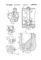
- FIG. 1 is a top plan view of a counterbalanced internal combustion engine
- FIG. 2 is an enlarged sectional view of the crankcase and counterbalance shaft equipped with the present invention
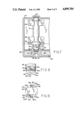
- FIG. 3 is a perspective view of the stub extension of the counterbalance shaft
- FIG. 4 is an end view of the stub extension
- FIG. 5 is a transverse sectional view taken along line 5--5 of FIG. 2 viewed in the direction of the arrows;
- FIG. 6 is an enlarged fragmentary longitudinal sectional view of the journal bearing and oil pump of the present invention.
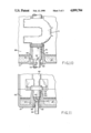
- FIG. 7 is a longitudinal sectional view of a crankcase and counterbalance shaft equipped with an alternate embodiment of the present invention.
- FIG. 8 is a perspective view of the stub extension of the alternate embodiment of FIG. 7.
- FIG. 9 is an end view of the stub extension of the alternate embodiment.
- FIG. 10 is an enlarged sectional view of a crankcase and crankshaft equipped with the present invention.
- FIG. 11 is an enlarged sectional view of the present invention used with a counterweight shaft extending outside the crankcase.
- engine 8 includes an inline counterbalance weight system having self-lubricating bearings of the present invention.
- Crankshaft 10 and counterbalance shaft 12 are disposed within crankcase 14 and piston 16 drives crankshaft 10 by movement of connecting rod 18.
- An inline counterbalance weight system compatible with the present invention is described in U.S. Pat. No. 4,800,852 and is incorporated by reference herein.
- FIG. 2 shows counterbalance shaft 12 disposed within upper and lower journal bearings 20 and 22, respectively, of crankcase 14. Disposed on counterbalance shaft 12 between bearings 20 and 22 are upper counterbalance weight 24, lower counterbalance weight 26, and counterbalance drive gear 28 which is below both counterbalance weights 24 and 26 and is driven by gear 27 connected to crankshaft 10. Located below counterbalance drive gear 28 is bearing wall 30, which receives shaft journal 32 and stub extension 34 of shaft 12. In an exemplary embodiment, journal 32 is approximately 0.75 inches long and stub extension 34 is approximately 0.5 inches long. Oil sump 36 is shown in FIG. 2 with the oil 37 at its full level which extends above the top of wall 30, providing lubricating oil to interior region or annual chamber 38 of bearing 22 via passage 40 and passage 42. The lubrication system of the present invention pumps lubricating oil from passage 40 to passage 42, thus lubricating bearing 22 and thrust bearing 43.
- Stub extension 34 has a notch or pocket 44 on its lower face 45.
- notch 44 has a depth of approximately 0.09 inches and a width, measured from the outer circumference inwardly along the radius, of approximately 0.125 inches.
- Extending across the outer circumference of stub extension 34 from notch 44 to shaft journal 32 is a half-circle shaped feed groove 46. The shape of notch 44 and groove 46 can be seen in FIGS. 3 and 4.
- Notch 44 is defined by side walls 44a and 44b and upper surface 44c.
- Side wall 44a is perpendicular to the tangent of the circumference of stub 34
- side wall 44b is parallel to lower wall 44a
- upper surface 44c is relatively parallel to lower axially facing surface 45.
- Stub 34 rotates in a clockwise direction in the embodiment shown in FIG. 4, and wall 44a faces the direction of rotation to positively urge oil flow in an outward radial direction.
- Bearing wall 30 has a feed channel 48 facing shaft journal 32 from below the lowest point of journal 32 to bearing passage 42, which is a small hollow formed on the upper edge of wall 30 (FIGS. 5 & 6).
- the outer surfaces of stub 34 are spaced from wall 30 and crankcase 14 to define annular chamber 38, and passage 40 connects chamber 38 to oil sump 36.
- Passage 40, interior region 38, feed channel 48, and bearing passage 42 provide the lubricating oil a path to traverse from oil sump 36 through lower journal 22 and back to oil sump 36. By this path, lubricating oil can be applied to bearings 32 and 43 even when oil sump 36 is as low as one-fourth full.
- the self-lubricating bearing rotates by the motion of counterbalance drive gear 28 driving counterbalance shaft 12.
- stub extension 34 Oil within pocket 44 is forced outwardly from the axis of rotation of counterbalance shaft 12 because of centrifugal force.
- the oil moving out of pocket 44 moves outwardly against wall 30 and at that point moves into feed groove 46.
- the oil is directed outwardly towards wall 30 into feed channel 48.
- Oil flows upwardly in channel 48 to lubricate journal bearing 22 and thrust bearing 43 (FIG. 2), and then flows outwardly through opening 42 in wall 30 whereupon it is returned to sump 36.
- From oil sump 36 the oil is drawn into passage 40 to reenter interior region 38.
- the level of oil sump 36 need only be to the height of the intake of passage 40, rather than the top of lower bearing 22 as is the case in immersion lubrication.
- Stub extension 50 is approximately 40% as long as stub extension 34 and slightly smaller in diameter, although bearing 52 is approximately the same length as journal 32.
- stub extension 50 is approximately 0.2 inches in height and 0.625 inches in diameter, with bearing 52 having a diameter of approximately 0.7485 inches.
- Lower bearing 22 also has an elongated feed channel 58 which extends from the bottom of stub extension 50 to the top of wall 30.
- Stub extension 50 has two pair of pockets 60 and feed grooves 62 disposed on opposite sides of its lower face 63.
- feed grooves 62 are angled with the rotation of stub extension 50 at approximately 45 degrees from the plane defined by the bottom of stub extension 50; and feed grooves 62 extend to a maximum length which includes a section within shoulder 54.
- Pockets 60 have a width, measured from the outer circumference inwardly along a line defined by sidewall 50b, of approximately 0.125 inches and a depth of approximately 0.09 inches.
- Pockets 60 are defined by side walls 60a and 60b and upper surface 60c.
- Side wall 60a is relatively parallel to a radius of stub 50 which is perpendicular to side wall 60b
- side wall 60b is relatively perpendicular to side wall 60a
- upper surface 60c is relatively parallel to lower face 63.
- the intersection of walls 60a and 60b forms a curved corner 60d rather than a right angle.
- FIGS. 7-9 The operation of the alternate embodiment depicted in FIGS. 7-9 is similar to that of the preferred embodiment.
- Stub passage 40, interior region 38, feed channel 58, and passage 42 provide the lubricating oil a path to flow from sump 36 through lower journal bearing 22 and back to oil sump 36.
- this embodiment increases the volume of oil pumped and improves its dry pumping ability.
- the present invention can also supply lubricating oil to an adjacent position, such as an adjacent bearing. If the invention is applied to an intermediate portion of a shaft disposed in a journal bearing, it is necessary for the shaft to be undercut immediately below pocket 44 so that oil can be drawn into pocket 44 and pumped upwardly. Although the invention is shown applied to a shaft in an internal combustion engine, it could alternatively be applied to other shafts in a power train, such as in a transmission or transaxle.
- journal 70 has an annular oil receiving channel 80 in communication with groove 78.
- Channel 80 is located at the bottom of feed channel 76 and provides a path for oil to flow during the entire rotation of crankshaft 72.
- crankshaft 72 extends outside crankcase 14, seal 82 is provided and defines an interior region 84. Oil enters interior region 84 via oil passage 86 from oil sump 88, creating an oil reservoir for pocket 68 to pump oil up feed channel 76 in a manner similar to that described above.
- counterweight shaft 90 extends outside crankcase 14 to serve as a power take-off and is sealed by seal 92.
- Journal 94 of shaft 90 is located within bearing 52.
- stub extension 50 At the end of journal portion 94 is stub extension 50, which in combination with bearing 52 has a similar configuration to FIG. 7 and further includes an additional shaft extension 96 located at the end of the lower facing surface.
- An interior region 98 is formed by seal 92, an annular shaft receiving recess 100, and shaft 90; interior region 98 provides an oil reservoir, in communication with oil sump 102 via passage 104, which provides oil for extension 50 to pump oil in a manner similar to that described above.
Landscapes
- Engineering & Computer Science (AREA)
- General Engineering & Computer Science (AREA)
- Mechanical Engineering (AREA)
- Chemical & Material Sciences (AREA)
- Combustion & Propulsion (AREA)
- Lubrication Of Internal Combustion Engines (AREA)
- Cylinder Crankcases Of Internal Combustion Engines (AREA)
- Sliding-Contact Bearings (AREA)
Abstract
Description
Claims (25)
Priority Applications (6)
| Application Number | Priority Date | Filing Date | Title |
|---|---|---|---|
| US07/348,862 US4899704A (en) | 1989-05-08 | 1989-05-08 | Self-lubricating bearing |
| CA000605595A CA1319868C (en) | 1989-05-08 | 1989-07-13 | Self-lubricating bearing |
| EP89122152A EP0396820B1 (en) | 1989-05-08 | 1989-12-01 | Self lubricating bearing |
| DE89122152T DE68907897T2 (en) | 1989-05-08 | 1989-12-01 | Self-lubricating bearing. |
| AU49847/90A AU619716B2 (en) | 1989-05-08 | 1990-02-16 | Self-lubricating bearing |
| JP2088116A JPH0652114B2 (en) | 1989-05-08 | 1990-04-02 | Self-lubricating bearing |
Applications Claiming Priority (1)
| Application Number | Priority Date | Filing Date | Title |
|---|---|---|---|
| US07/348,862 US4899704A (en) | 1989-05-08 | 1989-05-08 | Self-lubricating bearing |
Publications (1)
| Publication Number | Publication Date |
|---|---|
| US4899704A true US4899704A (en) | 1990-02-13 |
Family
ID=23369870
Family Applications (1)
| Application Number | Title | Priority Date | Filing Date |
|---|---|---|---|
| US07/348,862 Expired - Lifetime US4899704A (en) | 1989-05-08 | 1989-05-08 | Self-lubricating bearing |
Country Status (6)
| Country | Link |
|---|---|
| US (1) | US4899704A (en) |
| EP (1) | EP0396820B1 (en) |
| JP (1) | JPH0652114B2 (en) |
| AU (1) | AU619716B2 (en) |
| CA (1) | CA1319868C (en) |
| DE (1) | DE68907897T2 (en) |
Cited By (5)
| Publication number | Priority date | Publication date | Assignee | Title |
|---|---|---|---|---|
| US5156068A (en) * | 1990-04-04 | 1992-10-20 | Man Nutzfahrzeuge Aktiengesellschaft | Bearing means for compensating masses |
| US5651425A (en) * | 1994-09-09 | 1997-07-29 | Emerson Electric Co. | Passive lubrication delivery system and integral bearing housing |
| US20070215202A1 (en) * | 2006-03-20 | 2007-09-20 | Ferro Corporation | Aluminum-boron solar cell contacts |
| US20090101190A1 (en) * | 2006-03-20 | 2009-04-23 | Ferro Corporation | Solar Cell Contacts Containing Aluminum And At Least One Of Boron, Titanium, Nickel, Tin, Silver, Gallium, Zinc, Indium And Copper |
| US20100163101A1 (en) * | 2007-04-25 | 2010-07-01 | Ferro Corporation | Thick Film Conductor Formulations Comprising Silver And Nickel Or Silver And Nickel Alloys And Solar Cells Made Therefrom |
Families Citing this family (2)
| Publication number | Priority date | Publication date | Assignee | Title |
|---|---|---|---|---|
| JP3685810B2 (en) * | 1993-12-27 | 2005-08-24 | 本田技研工業株式会社 | Lubrication structure in engine output take-out device |
| DE102023109356A1 (en) | 2022-07-18 | 2024-01-18 | Prominent Gmbh | Drive unit for a motor metering pump |
Citations (15)
| Publication number | Priority date | Publication date | Assignee | Title |
|---|---|---|---|---|
| US2468948A (en) * | 1945-05-28 | 1949-05-03 | Gen Motors Corp | Sealed motor-compressor unit |
| US2628016A (en) * | 1946-03-05 | 1953-02-10 | Tecumseh Products Co | Refrigerating apparatus |
| US3003684A (en) * | 1957-05-29 | 1961-10-10 | Gen Electric | Refrigeration apparatus |
| US3616786A (en) * | 1969-06-10 | 1971-11-02 | Hatz Motoren | Internal combustion engine |
| US3712754A (en) * | 1969-12-05 | 1973-01-23 | Philips Corp | Dosing device |
| US3736076A (en) * | 1972-03-01 | 1973-05-29 | Cardinal Compressor Corp | Compressor lubrication system |
| US3794449A (en) * | 1971-08-31 | 1974-02-26 | Philips Corp | Viscosity pump |
| US3903995A (en) * | 1971-01-21 | 1975-09-09 | Outboard Marine Corp | Balancing system |
| US4325679A (en) * | 1980-07-22 | 1982-04-20 | White Consolidated Industries, Inc. | Oil pump for hermetic compressor |
| US4436490A (en) * | 1981-06-15 | 1984-03-13 | Siemens Aktiengesellschaft | Compressor and lubricating pump assembly |
| US4662328A (en) * | 1985-11-12 | 1987-05-05 | Tecumseh Products Company | Governor driven pump for an engine |
| US4664228A (en) * | 1985-02-14 | 1987-05-12 | Kubota Ltd. | Lubrication system for a vertical shaft engine |
| US4741303A (en) * | 1986-10-14 | 1988-05-03 | Tecumseh Products Company | Combination counterbalance and oil slinger for horizontal shaft engines |
| US4793301A (en) * | 1986-12-25 | 1988-12-27 | Fuji Jukogyo Kabushiki Kaisha | Lubricating system for an internal combustion engine |
| US4800852A (en) * | 1986-05-12 | 1989-01-31 | Tecumseh Products Company | Inline counterbalance weight system for a single cylinder engine |
Family Cites Families (5)
| Publication number | Priority date | Publication date | Assignee | Title |
|---|---|---|---|---|
| BE554859A (en) * | ||||
| US1886395A (en) * | 1930-07-24 | 1932-11-08 | Timken Silent Automatic Compan | Shaft bearing |
| GB890529A (en) * | 1959-10-06 | 1962-03-07 | Villiers Engineering Co Ltd | Force feed lubrication systems of internal combustion engines |
| US4375944A (en) * | 1976-09-13 | 1983-03-08 | Tecumseh Products Company | Lubricating device for a motor compressor |
| US4432693A (en) * | 1982-02-18 | 1984-02-21 | The Trane Company | Centrifugal pump impeller |
-
1989
- 1989-05-08 US US07/348,862 patent/US4899704A/en not_active Expired - Lifetime
- 1989-07-13 CA CA000605595A patent/CA1319868C/en not_active Expired - Fee Related
- 1989-12-01 EP EP89122152A patent/EP0396820B1/en not_active Expired - Lifetime
- 1989-12-01 DE DE89122152T patent/DE68907897T2/en not_active Expired - Fee Related
-
1990
- 1990-02-16 AU AU49847/90A patent/AU619716B2/en not_active Ceased
- 1990-04-02 JP JP2088116A patent/JPH0652114B2/en not_active Expired - Fee Related
Patent Citations (15)
| Publication number | Priority date | Publication date | Assignee | Title |
|---|---|---|---|---|
| US2468948A (en) * | 1945-05-28 | 1949-05-03 | Gen Motors Corp | Sealed motor-compressor unit |
| US2628016A (en) * | 1946-03-05 | 1953-02-10 | Tecumseh Products Co | Refrigerating apparatus |
| US3003684A (en) * | 1957-05-29 | 1961-10-10 | Gen Electric | Refrigeration apparatus |
| US3616786A (en) * | 1969-06-10 | 1971-11-02 | Hatz Motoren | Internal combustion engine |
| US3712754A (en) * | 1969-12-05 | 1973-01-23 | Philips Corp | Dosing device |
| US3903995A (en) * | 1971-01-21 | 1975-09-09 | Outboard Marine Corp | Balancing system |
| US3794449A (en) * | 1971-08-31 | 1974-02-26 | Philips Corp | Viscosity pump |
| US3736076A (en) * | 1972-03-01 | 1973-05-29 | Cardinal Compressor Corp | Compressor lubrication system |
| US4325679A (en) * | 1980-07-22 | 1982-04-20 | White Consolidated Industries, Inc. | Oil pump for hermetic compressor |
| US4436490A (en) * | 1981-06-15 | 1984-03-13 | Siemens Aktiengesellschaft | Compressor and lubricating pump assembly |
| US4664228A (en) * | 1985-02-14 | 1987-05-12 | Kubota Ltd. | Lubrication system for a vertical shaft engine |
| US4662328A (en) * | 1985-11-12 | 1987-05-05 | Tecumseh Products Company | Governor driven pump for an engine |
| US4800852A (en) * | 1986-05-12 | 1989-01-31 | Tecumseh Products Company | Inline counterbalance weight system for a single cylinder engine |
| US4741303A (en) * | 1986-10-14 | 1988-05-03 | Tecumseh Products Company | Combination counterbalance and oil slinger for horizontal shaft engines |
| US4793301A (en) * | 1986-12-25 | 1988-12-27 | Fuji Jukogyo Kabushiki Kaisha | Lubricating system for an internal combustion engine |
Cited By (8)
| Publication number | Priority date | Publication date | Assignee | Title |
|---|---|---|---|---|
| US5156068A (en) * | 1990-04-04 | 1992-10-20 | Man Nutzfahrzeuge Aktiengesellschaft | Bearing means for compensating masses |
| US5651425A (en) * | 1994-09-09 | 1997-07-29 | Emerson Electric Co. | Passive lubrication delivery system and integral bearing housing |
| US20070215202A1 (en) * | 2006-03-20 | 2007-09-20 | Ferro Corporation | Aluminum-boron solar cell contacts |
| US20090101190A1 (en) * | 2006-03-20 | 2009-04-23 | Ferro Corporation | Solar Cell Contacts Containing Aluminum And At Least One Of Boron, Titanium, Nickel, Tin, Silver, Gallium, Zinc, Indium And Copper |
| US8076570B2 (en) | 2006-03-20 | 2011-12-13 | Ferro Corporation | Aluminum-boron solar cell contacts |
| US8575474B2 (en) | 2006-03-20 | 2013-11-05 | Heracus Precious Metals North America Conshohocken LLC | Solar cell contacts containing aluminum and at least one of boron, titanium, nickel, tin, silver, gallium, zinc, indium and copper |
| US8759668B2 (en) | 2006-03-20 | 2014-06-24 | Heraeus Precious Metals North America Conshohocken Llc | Aluminum-boron solar cell contacts |
| US20100163101A1 (en) * | 2007-04-25 | 2010-07-01 | Ferro Corporation | Thick Film Conductor Formulations Comprising Silver And Nickel Or Silver And Nickel Alloys And Solar Cells Made Therefrom |
Also Published As
| Publication number | Publication date |
|---|---|
| EP0396820B1 (en) | 1993-07-28 |
| CA1319868C (en) | 1993-07-06 |
| DE68907897D1 (en) | 1993-09-02 |
| JPH0652114B2 (en) | 1994-07-06 |
| EP0396820A1 (en) | 1990-11-14 |
| DE68907897T2 (en) | 1993-11-11 |
| AU619716B2 (en) | 1992-01-30 |
| JPH02296098A (en) | 1990-12-06 |
| AU4984790A (en) | 1990-11-08 |
Similar Documents
| Publication | Publication Date | Title |
|---|---|---|
| US4637786A (en) | Scroll type fluid apparatus with lubrication of rotation preventing mechanism and thrust bearing | |
| JP2530179B2 (en) | Horizontal hermetic compressor | |
| US4718830A (en) | Bearing construction for refrigeration compresssor | |
| CN105715550A (en) | Pump body assembly and compressor with pump body assembly | |
| US4899704A (en) | Self-lubricating bearing | |
| US4543046A (en) | Rotary compressor | |
| JP3062436B2 (en) | Swash plate compressor | |
| US4325679A (en) | Oil pump for hermetic compressor | |
| KR860009237A (en) | Scroll fluid machine | |
| US6457561B1 (en) | Viscous pumping system | |
| US5707220A (en) | Centrifugal oil pump for a variable speed hermetic compressor | |
| KR870000135B1 (en) | Horizontal shaft oil pump | |
| JP2019002498A (en) | Holder for ball bearing and ball bearing | |
| US5252039A (en) | Enclosed motor-driven compressor | |
| CN1086447C (en) | Centrifugal oil pump for a variable speed hermetic compressor | |
| JPS61104189A (en) | Rotary electric compressor of closed vertical type | |
| CN216044298U (en) | Pump body subassembly and compressor | |
| CN111720423B (en) | Crankshaft assembly and engine | |
| SU1505108A1 (en) | Vertical pump | |
| JPH03179189A (en) | Oil feeder for scroll fluid machinery | |
| KR940007510Y1 (en) | Closed electric compressor | |
| KR890001738B1 (en) | Rotary type compressor | |
| JPS6038074Y2 (en) | Compressor oil supply device | |
| SU859728A1 (en) | Wave transmission | |
| JPH03294680A (en) | Scroll compressor |
Legal Events
| Date | Code | Title | Description |
|---|---|---|---|
| AS | Assignment |
Owner name: TECUMSEH PRODUCTS COMPANY, A CORP. OF MI, MICHIGAN Free format text: ASSIGNMENT OF ASSIGNORS INTEREST.;ASSIGNOR:KRONICH, PETER G.;REEL/FRAME:005071/0951 Effective date: 19890502 |
|
| STCF | Information on status: patent grant |
Free format text: PATENTED CASE |
|
| FEPP | Fee payment procedure |
Free format text: PAYOR NUMBER ASSIGNED (ORIGINAL EVENT CODE: ASPN); ENTITY STATUS OF PATENT OWNER: LARGE ENTITY |
|
| FPAY | Fee payment |
Year of fee payment: 4 |
|
| FPAY | Fee payment |
Year of fee payment: 8 |
|
| FPAY | Fee payment |
Year of fee payment: 12 |
|
| AS | Assignment |
Owner name: JPMORGAN CHASE BANK, N.A.,MICHIGAN Free format text: SECURITY AGREEMENT;ASSIGNOR:TECUMSEH PRODUCTS COMPANY;REEL/FRAME:016641/0380 Effective date: 20050930 Owner name: JPMORGAN CHASE BANK, N.A., MICHIGAN Free format text: SECURITY AGREEMENT;ASSIGNOR:TECUMSEH PRODUCTS COMPANY;REEL/FRAME:016641/0380 Effective date: 20050930 |
|
| AS | Assignment |
Owner name: CITICORP USA, INC.,NEW YORK Free format text: SECURITY INTEREST;ASSIGNORS:TECUMSEH PRODUCTS COMPANY;CONVERGENT TECHNOLOGIES INTERNATIONAL, INC.;TECUMSEH TRADING COMPANY;AND OTHERS;REEL/FRAME:017606/0644 Effective date: 20060206 Owner name: CITICORP USA, INC., NEW YORK Free format text: SECURITY INTEREST;ASSIGNORS:TECUMSEH PRODUCTS COMPANY;CONVERGENT TECHNOLOGIES INTERNATIONAL, INC.;TECUMSEH TRADING COMPANY;AND OTHERS;REEL/FRAME:017606/0644 Effective date: 20060206 |