US4899651A - Apron tensioning system for round balers - Google Patents
Apron tensioning system for round balers Download PDFInfo
- Publication number
- US4899651A US4899651A US07/256,831 US25683188A US4899651A US 4899651 A US4899651 A US 4899651A US 25683188 A US25683188 A US 25683188A US 4899651 A US4899651 A US 4899651A
- Authority
- US
- United States
- Prior art keywords
- apron
- bale
- pair
- tailgate
- round baler
- Prior art date
- Legal status (The legal status is an assumption and is not a legal conclusion. Google has not performed a legal analysis and makes no representation as to the accuracy of the status listed.)
- Expired - Lifetime
Links
Images

Classifications
-
- A—HUMAN NECESSITIES
- A01—AGRICULTURE; FORESTRY; ANIMAL HUSBANDRY; HUNTING; TRAPPING; FISHING
- A01F—PROCESSING OF HARVESTED PRODUCE; HAY OR STRAW PRESSES; DEVICES FOR STORING AGRICULTURAL OR HORTICULTURAL PRODUCE
- A01F15/00—Baling presses for straw, hay or the like
- A01F15/08—Details
- A01F15/0825—Regulating or controlling density or shape of the bale
- A01F15/0833—Regulating or controlling density or shape of the bale for round balers
Definitions
- This invention relates generally to roll baling machines typically referred to as "round balers" which form cylindrical bales of crop material and, in particular, to an apron tensioning system for such machines.
- Round balers of the expandable chamber type disclosed in U.S. Pat. Nos. 4,343,141 to F. A. Oellig et al and 4,426,833 to W. R. Campbell have included a bale forming apron which is maintained under tension during bale formation by utilizing coil springs or air springs.
- One drawback of the coil springs disclosed in the Oellig et al patent is that the tension in the apron cannot be quickly and easily released when servicing the baler.
- Another drawback of these coil springs is that they are bulky and heavy.
- the air springs disclosed in the Campbell patent overcome these drawbacks but they are costly and require additional frame structure due to the high forces they exert. Furthermore, adjustability of the air springs is limited to decreasing the apron tension only unless an on-board air supply is included.
- Another object of the present invention is to provide an apron tensioning system for round balers which permits the tension in the bale forming apron to be increased and decreased without including an on-board air supply.
- the present invention provides a system for tensioning an apron in a round baler having a main frame and a tailgate pivotally connected to the main frame.
- a sledge assembly is mounted on the main frame for movement between a bale starting position and a full bale position, and the apron is supported on take up means mounted in the main frame.
- the apron has an expandable inner course which cooperates with the sledge assembly to define a bale starting chamber when the sledge assembly is in the bale starting position.
- the take up means is movable from an inner position toward an outer position as the inner course of the apron expands.
- the apron tensioning system comprises spring means connected between the take up means and the tailgate for normally urging the take up means toward the inner position, and hydraulic means connected between the take up means and the tailgate for normally resisting movement of the take up means from the inner position to the outer position.
- the spring means comprises a pair of springs each having an upper end thereof connected to the take up means and a lower end thereof connected to the tailgate
- the hydraulic means comprises a pair of hydraulic cylinders each having one end thereof connected to the take up means and another end thereof connected to the tailgate.
- One of the springs and one of the hydraulic cylinders are disposed on each side of the baler.
- the hydraulic means provides a primary source of tension on the apron while the spring means provides a secondary source of tension on the apron.
- the spring means assists the hydraulic means during formation of a bale core in the bale starting chamber and during the final stages of bale formation.
- the apron tension generated by the hydraulic means increases during bale formation while the apron tension generated by the spring means remains substantially constant during bale formation.
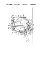
- FIG. 1 is a side elevational view of a round baler according to the preferred embodiment of the present invention at the start of bale formation;
- FIG. 2 is another side elevational view of the round baler of FIG. 1 at the completion of bale formation.
- a round baler 10 includes a main frame 12 supported by a pair of wheels 14.
- a tongue 16 is provided on the forward portion of the main frame 12 for connection to a tractor (not shown).
- a tailgate 18 is pivotally connected to the main frame 12 by stub shafts 20 so that the tailgate 18 may be closed as shown in FIG. 1 during bale formation and opened to eject a completed bale.
- a pair of hydraulic cylinders 21 are connected between the main frame 12 and the tailgate 18 to open and close the tailgate 18.
- a conventional pickup 22 is mounted on the main frame 12 by a pair of brackets 24 and is supported by a pair of wheels (not shown).
- the pickup 22 includes a plurality of fingers or tines 26 movable in a predetermined path to lift crop material from the ground and deliver it rearwardly toward a floor roll 28 which is rotatably mounted on the main frame 12.
- a sledge assembly 29 includes a plurality of rollers 30, 32, 34 extending transversely of the main frame 12 in an arcuate arrangement and journalled at the ends thereof in a pair of arcuately shaped arms 36.
- the arms 36 are pivotally mounted inside the main frame 12 on stub shafts 38 for permitting movement of the sledge assembly 29 between a bale starting position shown in FIG. 1 and a full bale position shown in FIG. 2.
- the rollers 30, 32, 34 are driven in a clockwise direction as indicated in FIG. 1 by conventional means (for example, chains and sprockets or gears) connected with a drive shaft 17 which is adapted for connection to the power take-off of a tractor (not shown).
- a stripper roll 39 is located adjacent roller 30 and is driven in a clockwise direction, as viewed in FIG. 1, to strip crop material from the roller 30.
- An idler roller 40 is carried by the arms 36 for movement in an arcuate path when the sledge assembly 29 moves between its bale starting and full bale positions. The idler roller 40 is freely rotatable.
- An apron 41 includes a plurality of belts 42 supported on guide rolls 44, 46, 48, 50, 52 which are rotatably mounted in the tailgate 18 and on a drive roll 54 which is rotatably mounted in the main frame 12.
- the belts 42 pass between the roller 34 and the idler roller 40, they are in engagement with only the idler roller 40 but the roller 34 is located in close proximity to the belts 42 to strip crop material from the belts 42.
- Further conventional means (not shown) are connected with the drive shaft 17 to provide rotation of the drive roll 54 in a direction which causes movement of the belts 42 along the path indicated in FIG. 1 when starting a bale.
- An additional guide roll 55 in the main frame 12 ensures proper driving engagement between the belts 42 and the drive roll 54.
- a pair of take up arms 56 are pivotally mounted on the main frame 12 by a cross shaft 58 for movement between inner and outer positions shown in FIGS. 1 and 2, respectively.
- Take up arms 56 carry additional guide rolls 60 and 62 for the belts 42.
- Resilient means such as a pair of springs 63 are provided to normally urge the arms 56 toward their inner positions.
- Springs 63 are connected at their upper ends to levers 59 which are mounted on the cross shaft 58 and at their lower ends to the tailgate 18.
- an inner course 42a of the apron belts 42 extending between the guide roll 52 and the idler roller 40 cooperates with the rollers 30, 32, 34 of the sledge assembly 29 to define a bale starting chamber 64.
- the apron inner course 42a forms a rear wall of the chamber 64 while the rollers 30, 32, 34 form a front wall of the chamber 64.
- the floor roll 28 is disposed in the bottom of the chamber 64 between the front and rear walls thereof.
- the roller 30 is spaced from the floor roll 28 to form a throat or inlet 66 for the chamber 64, and the take up arms 56 will be urged into their inner positions shown in FIG. 1 by the springs 63.
- the pickup tines 26 lift crop material from the ground and feed it into the bale starting chamber 64 via the throat 66.
- the crop material is carried rearwardly by the floor roll 28 into engagement with the apron inner course 42a which carries it upwardly and forwardly into engagement with the rollers 30, 32, 34.
- the crop material is coiled in a counterclockwise direction as viewed in FIG. 1 to start a bale core.
- Continued feeding of crop material into the chamber 64 by the pickup tines 26 causes the apron inner course 42a of the belts 42 to expand in length around a portion of the bale core as the diameter thereof increases.
- the take up arms 56 rotate from their inner position shown in FIG.
- the tailgate 18 is opened by extending hydraulic cylinders 21 and the bale is ejected. Subsequent closing of the tailgate 18 returns the apron inner course 42a to the location shown in FIG. 1 since the arms 56 are returned to their inner positions shown in FIG. 1 by springs 63.
- the round baler 10 is now ready to form another bale.
- sledge assembly 29 moves from its bale starting position of FIG. 1 to its full bale position of FIG. 2.
- This movement of the sledge assembly 29 causes the idler roller 40 to move in an arcuate path while maintaining the apron belts 42 in close proximity to the roller 34, thereby allowing the roller 34 to strip crop material from the apron belts 42.
- the idler roller 40 thus prevents the loss of crop material between the roller 34 and the belts 42 during formation of the bale.
- the sledge assembly 29 is pushed outwardly toward its full bale position during bale formation and is pulled inwardly toward its bale starting position during bale ejection without utilizing any additional mechanisms.
- apron 41 consists of a pair of chains connected together at spaced intervals by transverse slats, and the idler roller 40 is replaced by a pair of idler sprockets engaged with the chains.
- the guide rolls 44, 46, 48, 50, 52, 55, 60 and 62 would be replaced with guide sprockets for engaging the apron chains, and the drive roll 54 would be replaced with drive sprockets.
- a pair of hydraulic cylinders 68 are pivotally connected at their ends between lever arms 70 which are mounted on the cross shaft 58 and frame members 72 on the tailgate 18.
- the hydraulic cylinders 68 are preferably of the double acting type.
- One of the springs 63 and one of the hydraulic cylinders 68 are disposed on each side of the baler 10.
- the longitudinal axes of the hydraulic cylinders 68 are inclined at an acute angle of approximately 30° relative to the longitudinal axes of the springs 63 at the start of bale formation. This angle of inclination between the cylinders 68 and the springs 63 decreases to approximately 10° as seen in FIG. 2 when a full bale has been completed.
- the hydraulic cylinders 68 are extended in order to resist movement of the arms 56 from the inner positions shown in FIG. 1 to the outer positions shown in FIG. 2. This maintains tension in the apron 41 and thereby controls the density of bales formed in the baler 10.
- the hydraulic cylinders 68 are contracted.
- the springs 63 and the hydraulic cylinders 68 cooperate to comprise an apron tensioning system according to the present invention.
- the hydraulic cylinders 68 provide a primary source of tension on the apron 41 while the springs 63 provide a secondary source of tension on the apron 41 and assist the cylinders 68 during formation of the bale core and during the final stages of bale formation.
- the apron tension generated by the hydraulic cylinders 68 increases during bale formation while the apron tension generated by the springs 63 remains substantially constant during bale formation.
- This cooperation between the springs 63 and the hydraulic cylinders 68 ensures that bales formed in the baler 10 have dense cores and hard outer shells. Such bales are preferred because the dense cores prevent bales from sagging or squatting after formation and the hard outer shells help to shed water and thus prevent it from penetrating into the bales.
Landscapes
- Life Sciences & Earth Sciences (AREA)
- Environmental Sciences (AREA)
- Harvester Elements (AREA)
- Harvesting Machines For Specific Crops (AREA)
- Storage Of Harvested Produce (AREA)
Priority Applications (4)
| Application Number | Priority Date | Filing Date | Title |
|---|---|---|---|
| US07/256,831 US4899651A (en) | 1988-10-11 | 1988-10-11 | Apron tensioning system for round balers |
| CA000611878A CA1322290C (fr) | 1988-10-11 | 1989-09-19 | Dispositif de raidissement de tablier de ramasseuse-presse a balles cylindriques |
| EP89202541A EP0364042B1 (fr) | 1988-10-11 | 1989-10-09 | Système régulateur de la densité des balles rondes |
| DE89202541T DE68911838T2 (de) | 1988-10-11 | 1989-10-09 | Riemenspannungsvorrichtung für eine Rundballenpresse. |
Applications Claiming Priority (1)
| Application Number | Priority Date | Filing Date | Title |
|---|---|---|---|
| US07/256,831 US4899651A (en) | 1988-10-11 | 1988-10-11 | Apron tensioning system for round balers |
Publications (1)
| Publication Number | Publication Date |
|---|---|
| US4899651A true US4899651A (en) | 1990-02-13 |
Family
ID=22973764
Family Applications (1)
| Application Number | Title | Priority Date | Filing Date |
|---|---|---|---|
| US07/256,831 Expired - Lifetime US4899651A (en) | 1988-10-11 | 1988-10-11 | Apron tensioning system for round balers |
Country Status (4)
| Country | Link |
|---|---|
| US (1) | US4899651A (fr) |
| EP (1) | EP0364042B1 (fr) |
| CA (1) | CA1322290C (fr) |
| DE (1) | DE68911838T2 (fr) |
Cited By (9)
| Publication number | Priority date | Publication date | Assignee | Title |
|---|---|---|---|---|
| US4956968A (en) * | 1989-12-11 | 1990-09-18 | Ford New Holland, Inc. | Round baler with mechanism for dispensing wrapping material |
| US5367865A (en) * | 1993-08-13 | 1994-11-29 | Ford New Holland, Inc. | Round baler apron tensioning apparatus |
| US5931089A (en) * | 1997-03-07 | 1999-08-03 | Gehl Company | Bale starting chamber with tensioning device |
| US6745681B2 (en) | 2001-10-30 | 2004-06-08 | Deere & Company | Light discharge gate for large round baler |
| US20050198935A1 (en) * | 2004-03-12 | 2005-09-15 | Duratech Industries International, Inc. | Round baler leaf reclamation device |
| US20050198934A1 (en) * | 2004-03-12 | 2005-09-15 | Duratech Industries International, Inc. | Round baler reclamation belt |
| US20110060507A1 (en) * | 2009-09-08 | 2011-03-10 | Olivier Vanhercke | Implement initiated control of tractor power take-off (pto) |
| US9622419B2 (en) | 2012-05-09 | 2017-04-18 | Cnh Industrial America Llc | Accumulator system for round baler belt pre-tension |
| US11134614B2 (en) * | 2018-10-10 | 2021-10-05 | Deere & Company | Productivity increase for a round baler |
Families Citing this family (3)
| Publication number | Priority date | Publication date | Assignee | Title |
|---|---|---|---|---|
| DE4025467A1 (de) * | 1990-08-10 | 1992-02-13 | Zweegers & Zonen P J | Erntegutpresse |
| DE19851470B4 (de) * | 1998-11-09 | 2006-09-28 | Welger Maschinenfabrik Gmbh | Rundballenpresse für landwirtschaftliches Erntegut |
| DE19941604C1 (de) * | 1999-09-01 | 2000-10-26 | Claas Usines France | Stelleinrichtung für Funktionselemente an einer Rollballenpresse |
Citations (24)
| Publication number | Priority date | Publication date | Assignee | Title |
|---|---|---|---|---|
| US3722197A (en) * | 1972-01-03 | 1973-03-27 | G Vermeer | Method and machine for forming a large round bale of a fibrous material |
| US3751890A (en) * | 1971-06-17 | 1973-08-14 | Starline | Ground engaging hay bale rolling apparatus |
| SU411805A1 (fr) * | 1972-04-27 | 1974-01-25 | ||
| US3837159A (en) * | 1973-11-23 | 1974-09-24 | G Vermeer | Machine for forming a round bale of a windrowed material |
| US4103475A (en) * | 1976-08-30 | 1978-08-01 | Chromalloy American Corporation | Apparatus for forming a bale of hay |
| US4137697A (en) * | 1977-03-18 | 1979-02-06 | International Harvester Company | Bale density structure for cylindrical balers |
| US4257219A (en) * | 1979-08-27 | 1981-03-24 | Gehl Company | Cylindrical bale forming machine having hydraulic control means for controlling the bale density |
| US4273036A (en) * | 1978-06-09 | 1981-06-16 | Kopaska Arnold F | Machine for rolling crops into round bales |
| US4280320A (en) * | 1978-08-25 | 1981-07-28 | Sperry Corporation | Tensioning apparatus |
| GB2090560A (en) * | 1980-12-09 | 1982-07-14 | Brockdale Developments Ltd | Agricultural baling machine |
| US4343141A (en) * | 1981-09-16 | 1982-08-10 | Sperry Corporation | Baling machine with improved arm assembly for controlling expansion of the upper apron |
| SU954050A1 (ru) * | 1981-03-17 | 1982-08-30 | Фрунзенский Конструкторско-Технологический Институт По Кормоуборочным Машинам | Рулонный пресс-подборщик |
| US4391187A (en) * | 1981-10-05 | 1983-07-05 | Deere & Company | Belt-tensioning system for round balers |
| US4393764A (en) * | 1980-08-20 | 1983-07-19 | Deere & Company | Round baler with a discharge gate for rearwardly moving a bale |
| SU1029892A1 (ru) * | 1982-02-16 | 1983-07-23 | Казахское Научно-Производственное Объединение Механизации И Электрификации Сельского Хозяйства | Пресс дл волокнистых материалов |
| US4426833A (en) * | 1981-12-21 | 1984-01-24 | Sperry Corporation | Baling machine with air spring means for maintaining apron tension |
| US4433619A (en) * | 1981-10-05 | 1984-02-28 | Deere & Company | Method for unplugging cylindrical baler |
| US4437399A (en) * | 1982-05-28 | 1984-03-20 | Deere & Company | Twine-wrapping mechanism for mechanism for a large round baler |
| US4444098A (en) * | 1982-05-28 | 1984-04-24 | Deere & Company | Cylindrical baler with self-cleaning gate |
| US4545298A (en) * | 1983-07-04 | 1985-10-08 | Deere & Company | Cylindrical baler hydraulic circuit for controlling bale chamber tension and operating bale discharge gate |
| SU1192711A1 (ru) * | 1984-06-21 | 1985-11-23 | Казахский Филиал Всесоюзного Научно-Исследовательского Инстиута Комбикормовой Промышленности | Рулонный пресс дл прессовани волокнистых материалов |
| US4656820A (en) * | 1986-05-08 | 1987-04-14 | New Holland Inc. | Round baler apron tensioning system |
| US4698955A (en) * | 1986-02-18 | 1987-10-13 | Wagstaff Robert A | Bale density control system for round balers |
| US4759278A (en) * | 1986-03-05 | 1988-07-26 | Deere & Company | Machine for forming cylindrical bales of crop |
Family Cites Families (1)
| Publication number | Priority date | Publication date | Assignee | Title |
|---|---|---|---|---|
| FR2541560B1 (fr) * | 1983-02-25 | 1985-08-30 | Rivierre Casalis | Dispositif tendeur de courroies de formage de balles cylindriques dans une presse de produits agricoles |
-
1988
- 1988-10-11 US US07/256,831 patent/US4899651A/en not_active Expired - Lifetime
-
1989
- 1989-09-19 CA CA000611878A patent/CA1322290C/fr not_active Expired - Lifetime
- 1989-10-09 DE DE89202541T patent/DE68911838T2/de not_active Expired - Lifetime
- 1989-10-09 EP EP89202541A patent/EP0364042B1/fr not_active Expired - Lifetime
Patent Citations (24)
| Publication number | Priority date | Publication date | Assignee | Title |
|---|---|---|---|---|
| US3751890A (en) * | 1971-06-17 | 1973-08-14 | Starline | Ground engaging hay bale rolling apparatus |
| US3722197A (en) * | 1972-01-03 | 1973-03-27 | G Vermeer | Method and machine for forming a large round bale of a fibrous material |
| SU411805A1 (fr) * | 1972-04-27 | 1974-01-25 | ||
| US3837159A (en) * | 1973-11-23 | 1974-09-24 | G Vermeer | Machine for forming a round bale of a windrowed material |
| US4103475A (en) * | 1976-08-30 | 1978-08-01 | Chromalloy American Corporation | Apparatus for forming a bale of hay |
| US4137697A (en) * | 1977-03-18 | 1979-02-06 | International Harvester Company | Bale density structure for cylindrical balers |
| US4273036A (en) * | 1978-06-09 | 1981-06-16 | Kopaska Arnold F | Machine for rolling crops into round bales |
| US4280320A (en) * | 1978-08-25 | 1981-07-28 | Sperry Corporation | Tensioning apparatus |
| US4257219A (en) * | 1979-08-27 | 1981-03-24 | Gehl Company | Cylindrical bale forming machine having hydraulic control means for controlling the bale density |
| US4393764A (en) * | 1980-08-20 | 1983-07-19 | Deere & Company | Round baler with a discharge gate for rearwardly moving a bale |
| GB2090560A (en) * | 1980-12-09 | 1982-07-14 | Brockdale Developments Ltd | Agricultural baling machine |
| SU954050A1 (ru) * | 1981-03-17 | 1982-08-30 | Фрунзенский Конструкторско-Технологический Институт По Кормоуборочным Машинам | Рулонный пресс-подборщик |
| US4343141A (en) * | 1981-09-16 | 1982-08-10 | Sperry Corporation | Baling machine with improved arm assembly for controlling expansion of the upper apron |
| US4391187A (en) * | 1981-10-05 | 1983-07-05 | Deere & Company | Belt-tensioning system for round balers |
| US4433619A (en) * | 1981-10-05 | 1984-02-28 | Deere & Company | Method for unplugging cylindrical baler |
| US4426833A (en) * | 1981-12-21 | 1984-01-24 | Sperry Corporation | Baling machine with air spring means for maintaining apron tension |
| SU1029892A1 (ru) * | 1982-02-16 | 1983-07-23 | Казахское Научно-Производственное Объединение Механизации И Электрификации Сельского Хозяйства | Пресс дл волокнистых материалов |
| US4437399A (en) * | 1982-05-28 | 1984-03-20 | Deere & Company | Twine-wrapping mechanism for mechanism for a large round baler |
| US4444098A (en) * | 1982-05-28 | 1984-04-24 | Deere & Company | Cylindrical baler with self-cleaning gate |
| US4545298A (en) * | 1983-07-04 | 1985-10-08 | Deere & Company | Cylindrical baler hydraulic circuit for controlling bale chamber tension and operating bale discharge gate |
| SU1192711A1 (ru) * | 1984-06-21 | 1985-11-23 | Казахский Филиал Всесоюзного Научно-Исследовательского Инстиута Комбикормовой Промышленности | Рулонный пресс дл прессовани волокнистых материалов |
| US4698955A (en) * | 1986-02-18 | 1987-10-13 | Wagstaff Robert A | Bale density control system for round balers |
| US4759278A (en) * | 1986-03-05 | 1988-07-26 | Deere & Company | Machine for forming cylindrical bales of crop |
| US4656820A (en) * | 1986-05-08 | 1987-04-14 | New Holland Inc. | Round baler apron tensioning system |
Non-Patent Citations (2)
| Title |
|---|
| John Deere Operator s Manual 430 and 530 Round Balers, pp. 34 4 and 35 5, SP 319 Litho in U.S.A., Nov. 1984. * |
| John Deere Operator's Manual--430 and 530 Round Balers, pp. 34-4 and 35-5, SP-319 Litho in U.S.A., Nov. 1984. |
Cited By (12)
| Publication number | Priority date | Publication date | Assignee | Title |
|---|---|---|---|---|
| US4956968A (en) * | 1989-12-11 | 1990-09-18 | Ford New Holland, Inc. | Round baler with mechanism for dispensing wrapping material |
| US5367865A (en) * | 1993-08-13 | 1994-11-29 | Ford New Holland, Inc. | Round baler apron tensioning apparatus |
| US5931089A (en) * | 1997-03-07 | 1999-08-03 | Gehl Company | Bale starting chamber with tensioning device |
| US6745681B2 (en) | 2001-10-30 | 2004-06-08 | Deere & Company | Light discharge gate for large round baler |
| US20050198935A1 (en) * | 2004-03-12 | 2005-09-15 | Duratech Industries International, Inc. | Round baler leaf reclamation device |
| US20050198934A1 (en) * | 2004-03-12 | 2005-09-15 | Duratech Industries International, Inc. | Round baler reclamation belt |
| US7337603B2 (en) | 2004-03-12 | 2008-03-04 | Duratech Industries International, Inc. | Round baler leaf reclamation device |
| US20110060507A1 (en) * | 2009-09-08 | 2011-03-10 | Olivier Vanhercke | Implement initiated control of tractor power take-off (pto) |
| US8311709B2 (en) * | 2009-09-08 | 2012-11-13 | Cnh America Llc | Implement initiated control of tractor power take-off (PTO) |
| US9622419B2 (en) | 2012-05-09 | 2017-04-18 | Cnh Industrial America Llc | Accumulator system for round baler belt pre-tension |
| US10383285B2 (en) | 2012-05-09 | 2019-08-20 | Cnh Industrial America Llc | Accumulator system for round baler belt pre-tension |
| US11134614B2 (en) * | 2018-10-10 | 2021-10-05 | Deere & Company | Productivity increase for a round baler |
Also Published As
| Publication number | Publication date |
|---|---|
| DE68911838D1 (de) | 1994-02-17 |
| EP0364042A1 (fr) | 1990-04-18 |
| EP0364042B1 (fr) | 1993-12-29 |
| DE68911838T2 (de) | 1994-05-05 |
| CA1322290C (fr) | 1993-09-21 |
Similar Documents
| Publication | Publication Date | Title |
|---|---|---|
| US4956968A (en) | Round baler with mechanism for dispensing wrapping material | |
| US4870812A (en) | Round baler with variable bale chamber | |
| US6021622A (en) | Round bale wrapping apparatus | |
| US5581973A (en) | Apparatus for making round bales | |
| US5243806A (en) | Apparatus for wrapping round bales with sheet material | |
| US4212149A (en) | Crop baling machines | |
| US5426923A (en) | Net supply apparatus for round balers | |
| EP0954960B1 (fr) | Système de contrôle de la tension pour une machine de formation de balles rondes | |
| US5367865A (en) | Round baler apron tensioning apparatus | |
| US4899651A (en) | Apron tensioning system for round balers | |
| US5581976A (en) | Method for wrapping round bales | |
| CA2028022C (fr) | Dispositif d'emballage des balles pour ramasseuse-presse a balle cylindrique | |
| US5479767A (en) | Trash baffle for round baler | |
| EP0432830B1 (fr) | Appareil pour envelopper une balle dans une presse à balles rondes | |
| US5191833A (en) | Roll stripping apparatus for round baler | |
| US5598690A (en) | Tailgate latching apparatus for a round baler | |
| US5319899A (en) | Net severing apparatus for round baler | |
| US5230193A (en) | Net spreading apparatus for round baler | |
| US4912918A (en) | Apron tensioning method for round balers | |
| US5259167A (en) | Control mechanism for round baler web cutting apparatus | |
| US5020299A (en) | Method of wrapping round bales | |
| US4135352A (en) | Semicontinuous large round baling machine | |
| US5448873A (en) | Net knife for round baler | |
| EP0339730B1 (fr) | Presse à balles rondes avec chambre variable et ensemble presseur | |
| US6722100B1 (en) | Simplified wrap material dispenser for crop bales |
Legal Events
| Date | Code | Title | Description |
|---|---|---|---|
| AS | Assignment |
Owner name: FORD NEW HOLLAND, INC., NEW HOLLAND, PA, A CORP. O Free format text: ASSIGNMENT OF ASSIGNORS INTEREST.;ASSIGNORS:LAUSCH, H. NEVIN;WAGSTAFF, ROBERT A.;JENNINGS, RICHARD E.;REEL/FRAME:004970/0147 Effective date: 19881005 Owner name: FORD NEW HOLLAND, INC., PENNSYLVANIA Free format text: ASSIGNMENT OF ASSIGNORS INTEREST;ASSIGNORS:LAUSCH, H. NEVIN;WAGSTAFF, ROBERT A.;JENNINGS, RICHARD E.;REEL/FRAME:004970/0147 Effective date: 19881005 |
|
| STCF | Information on status: patent grant |
Free format text: PATENTED CASE |
|
| CC | Certificate of correction | ||
| FPAY | Fee payment |
Year of fee payment: 4 |
|
| SULP | Surcharge for late payment | ||
| AS | Assignment |
Owner name: BLUE LEAF I.P., INC., DELAWARE Free format text: ASSIGNMENT OF ASSIGNORS INTEREST;ASSIGNOR:FORD NEW HOLLAND, INC.;REEL/FRAME:007388/0102 Effective date: 19941215 |
|
| FPAY | Fee payment |
Year of fee payment: 8 |
|
| FPAY | Fee payment |
Year of fee payment: 12 |