US4899596A - Self-calibrating torque measuring system - Google Patents
Self-calibrating torque measuring system Download PDFInfo
- Publication number
- US4899596A US4899596A US07/189,976 US18997688A US4899596A US 4899596 A US4899596 A US 4899596A US 18997688 A US18997688 A US 18997688A US 4899596 A US4899596 A US 4899596A
- Authority
- US
- United States
- Prior art keywords
- drive shaft
- torque
- indicia
- shaft
- phase shift
- Prior art date
- Legal status (The legal status is an assumption and is not a legal conclusion. Google has not performed a legal analysis and makes no representation as to the accuracy of the status listed.)
- Expired - Fee Related
Links
- 230000010363 phase shift Effects 0.000 claims abstract description 46
- 238000000034 method Methods 0.000 claims abstract description 10
- 238000012545 processing Methods 0.000 claims description 7
- 230000002093 peripheral effect Effects 0.000 claims description 6
- 238000006073 displacement reaction Methods 0.000 claims description 3
- 230000002459 sustained effect Effects 0.000 claims 1
- 230000001419 dependent effect Effects 0.000 abstract description 5
- 238000004519 manufacturing process Methods 0.000 description 9
- 230000005404 monopole Effects 0.000 description 6
- 238000005259 measurement Methods 0.000 description 5
- 238000009434 installation Methods 0.000 description 4
- 238000010276 construction Methods 0.000 description 2
- 238000012937 correction Methods 0.000 description 2
- 238000012423 maintenance Methods 0.000 description 2
- 239000007787 solid Substances 0.000 description 2
- 238000003466 welding Methods 0.000 description 2
- 239000000356 contaminant Substances 0.000 description 1
- 238000011161 development Methods 0.000 description 1
- 238000010586 diagram Methods 0.000 description 1
- 238000005304 joining Methods 0.000 description 1
- 238000003754 machining Methods 0.000 description 1
- 238000012986 modification Methods 0.000 description 1
- 230000004048 modification Effects 0.000 description 1
- 238000007747 plating Methods 0.000 description 1
- 125000006850 spacer group Chemical group 0.000 description 1
Images

Classifications
-
- G—PHYSICS
- G01—MEASURING; TESTING
- G01L—MEASURING FORCE, STRESS, TORQUE, WORK, MECHANICAL POWER, MECHANICAL EFFICIENCY, OR FLUID PRESSURE
- G01L25/00—Testing or calibrating of apparatus for measuring force, torque, work, mechanical power, or mechanical efficiency
- G01L25/003—Testing or calibrating of apparatus for measuring force, torque, work, mechanical power, or mechanical efficiency for measuring torque
-
- G—PHYSICS
- G01—MEASURING; TESTING
- G01L—MEASURING FORCE, STRESS, TORQUE, WORK, MECHANICAL POWER, MECHANICAL EFFICIENCY, OR FLUID PRESSURE
- G01L3/00—Measuring torque, work, mechanical power, or mechanical efficiency, in general
- G01L3/02—Rotary-transmission dynamometers
- G01L3/04—Rotary-transmission dynamometers wherein the torque-transmitting element comprises a torsionally-flexible shaft
- G01L3/10—Rotary-transmission dynamometers wherein the torque-transmitting element comprises a torsionally-flexible shaft involving electric or magnetic means for indicating
- G01L3/101—Rotary-transmission dynamometers wherein the torque-transmitting element comprises a torsionally-flexible shaft involving electric or magnetic means for indicating involving magnetic or electromagnetic means
-
- G—PHYSICS
- G01—MEASURING; TESTING
- G01L—MEASURING FORCE, STRESS, TORQUE, WORK, MECHANICAL POWER, MECHANICAL EFFICIENCY, OR FLUID PRESSURE
- G01L3/00—Measuring torque, work, mechanical power, or mechanical efficiency, in general
- G01L3/02—Rotary-transmission dynamometers
- G01L3/04—Rotary-transmission dynamometers wherein the torque-transmitting element comprises a torsionally-flexible shaft
- G01L3/10—Rotary-transmission dynamometers wherein the torque-transmitting element comprises a torsionally-flexible shaft involving electric or magnetic means for indicating
- G01L3/109—Rotary-transmission dynamometers wherein the torque-transmitting element comprises a torsionally-flexible shaft involving electric or magnetic means for indicating involving measuring phase difference of two signals or pulse trains
Definitions
- the present invention relates generally to a system including method and apparatus for measuring the torque transmitted by a shaft and, in particular, a system which automatically compensates for variations in wall thickness exhibited by different drive shafts having the same nominal dimensions.
- the present invention is particularly suited for use with monopole variable reluctance torque measuring apparatus of the type disclosed in U.S. Pat. Nos. 3,548,649 and 4,488,443, although its use need not be so restricted.
- the prior art has included various systems for measuring transmitted shaft torque by measuring the "twist" or torsional deflection of a length of the shaft while it is under a torsional load.
- a pair of toothed wheels are physically attached to spaced apart respective locations along the shaft and the relative displacement between the teeth of these two wheels is then detected by a suitable electrical signal transducer.
- photo-electric or variable reluctance sensors may be utilized to detect the relative positions of teeth in the two toothed wheels.
- the toothed wheels are physically located substantially adjacent to one another although the relative rotational position of at least one of the wheels is determined by a tubular sleeve structure actually affixed to the shaft at some more significant distance away from the other wheel. In this way, sufficient shaft length is included so as to produce a desired magnitude of relative rotational movement between the toothed wheels when the shaft is torsionally loaded to a predetermined magnitude.
- the teeth are, at least in part, axially extended with the teeth on one wheel being interleaved between those on the other wheel and with a single pole variable reluctance sensor disposed to monitor the overlapped portions of such teeth as they rotate therepast. This arrangement is depicted in the exemplary embodiments of the above-referenced related patents.
- the monopole sensor produces a voltage pulse as each target tooth crosses its path.
- a string of voltage pulses is produced over a period of time as the shafts rotate teeth past the sensor.
- the phase relation of these pulses is caused to shift as the drive shaft twists under load and moves its target teeth.
- Calculation of torque is made with a digital computer software program which correlates the measured twist or phase shift of the drive shaft with the magnitude of the torque being transmitted through the shaft. This correlation is based on the geometry of the shaft and its elastic modulus at a given temperature. Torque measurement accuracy is dependent upon both characteristics. However, temperature is measured and modulus is consistent from one shaft to another. Therefore, most variations in accuracy of torque measuring apparatus previously in use can be attributed to variations in shaft geometry (that is, wall thickness) from unit to unit in large production lots.
- the need to manually program the signal processing circuitry to compensate for a particular shaft in a particular installation not only imposes added administrative overhead to successful system operation, it also increases the chance that an erroneous signal compensation will in fact be effected if the manually entered compensation data is not properly coordinated with the actual shaft in a given installation. This includes situations where a different set of electronics may be associated with a given shaft during field installation and/or maintenance procedures.
- differential tooth height that is, the radial tooth dimension
- differential amplitude modulation component related to gap size Since signal components related to speed are also inherently present, and since the differential pulse amplitude corresponds to the encoded shaft modulus data, the signal processing circuitry of the exemplary torque meter is also enabled to automatically compensate for errors induced by gap size between adjacent teeth, speed and shaft modulus for any given system.
- the invention relates to a universal torque measuring system for hollow drive shafts which automatically compensates for variations in wall thickness exhibited by different drive shafts having the same nominal dimensions.
- Each drive shaft has a plurality of first target teeth thereon at spaced peripheral locations.
- An elongated reference shaft coaxial with the drive shaft has a plurality of second target teeth thereon corresponding to the first target teeth.
- the drive shaft is subjected to a first predetermined torque which causes a certain amount of twist dependent upon its wall thickness.
- the reference shaft is affixed to the drive shaft such that the second target teeth are angularly displaced from the first target teeth to produce an initial phase shift.
- the first target teeth are set in position during calibration, with the reference shaft geometry being held fixed.
- the shaft is incorporated into an engine and rotated under load subjecting it to a second predetermined torque less than the first predetermined torque, there is a resulting second phase shift.
- This second phase shift and the second predetermined torque define a second operating condition of the drive shaft.
- the first and second operating conditions define a characteristic relationship between torque and phase shift for the drive shaft.
- a sensor is positioned to detect deviations in phase shift of the first and second target teeth from the initial phase shift and generates a signal proportional to such deviations.
- a microprocessor is responsive to the signal from the sensor for automatically deriving a value of torque being experienced by the drive shaft as a function of each such deviation according to the characteristic relationship.
- a routine has been devised to eliminate any component matching or manual adjustment in the monopole torque meter system without sacrificing system accuracy.
- the new routine uses conventional "zeroing" of the torque meter in the calibration rig, although the adjustment is made at a standardized load value on the high end of the torque scale, rather than at zero torque. All shafts produced are “zeroed” at one value in this manner.
- the microprocessor used for torque calculation is programmed also to "read" the phase relationship from the sensor during engine running at a known low-torque condition.
- the read value after a simple validity check, is stored in computer memory, and used as a second point in defining the phase-torque characteristic for that shaft.
- the torquemeter system performs a self-calibration each time it reads the low torque phase shift.
- the known low torque value can be defined with acceptable accuracy for a given type of powerplant, knowing other dependent characteristics, for example, core speed, output speed, load application control position, day temperature and shaft temperature. During the "read" function, these other characteristics are measured exactly.
- the validity of the read signal can be established by comparing the current value to a stored average of the last five values, or some other suitable reasonableness check can be performed. If the current sample is not acceptable, an error warning can be made by the computer, and the last reasonable value recorded can be used.
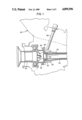
- FIG. 1 is a detail side elevation view, certain parts cut away and shown in section, of a gas turbine engine which incorporates a drive shaft embodying the present invention
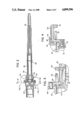
- FIG. 2 is a longitudinal cross section view of the novel drive shaft illustrated in FIG. 1;
- FIGS. 3 and 4 are detail cross section views of components illustrated in FIG. 2;
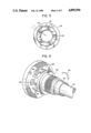
- FIG. 5 is a cross section view taken generally along line 5--5 in FIG. 2;
- FIG. 6 is a detail perspective view illustrating parts shown in FIGS. 1-5;
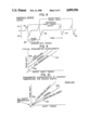
- FIG. 7 is a schematic block diagram illustrating important components of the invention.
- FIG. 8 illustrates the output of a sensor which is utilized with the invention.
- FIGS. 9, 10, and 11 are graphs indicating phase shift as a function of torque and utilized to explain the invention, FIG. 11 being representative of the invention.
- FIG. 1 illustrates portions of a gas turbine engine 20 which utilizes a universal torque measuring system in accordance with the invention. While the engine 20 is illustrated as being a gas turbine engine, indeed, it may be any form of prime mover. That is, the benefits and advantages of the invention are of a universal nature and need not be restricted to gas turbine engines.
- the gas turbine engine 20 has a turbine at the aft end (not shown) with a drive shaft 30.
- a mounting flange 28 at an extreme end of the drive shaft 30 is attached to a similar mounting flange 26 provided at an extreme end of an output shaft 24 and the flanges 26, 28 are firmly joined by means of a plurality of mounting bolts 32 such that the shafts 24 and 30 are aligned and coaxial.
- FIG. 2 which more clearly illustrates the drive shaft 30 as it extends away from the output shaft 24.
- a reference shaft 34 which may be solid or hollow, as desired, is fixed to the drive shaft 30 at a location distant from the flange 28 by means of a pin 36.
- the outer diameter of the reference shaft 34 is slightly smaller than the inner diameter of the drive shaft 30.
- the shafts 30 and 34 do not rotate relative to one another to any appreciable extent, they are separated by means of a plurality of annular spacers 38 which may, for example, be formed by plasma plating on the outer surface of the reference shaft.
- the drive shaft 30 and the reference shaft 34 are maintained in substantially coaxial alignment, and the reference shaft 34 floats freely relative to the drive shaft 30 in the region proximate to the output shaft 24.
- a reference ring 40 (see FIGS. 1-4) is mounted on and fixed to the drive shaft 30 by means of welding or in some other suitable fashion at a location longitudinally spaced from the mounting flange 28.
- a plurality of target teeth 42 integral with the reference ring 40 extend away from the ring in a direction toward the flange 28.
- the target teeth are preferably, although not necessarily, equally spaced peripherally on the reference ring and extend in directions which are substantially parallel to the longitudinal axis of the drive shaft.
- a cap 44 is fixed to the shaft 34 by means of a pin 46.
- An O-ring seal 48 (FIG. 4) is supported by the cap 44 and engages the inner surface of the drive shaft 30 and serves to prevent undesirable entry of contaminants into the region between the shafts 30 and 34.
- a second reference ring 50 (FIGS. 1, 3, and 4) is suitably fixed onto the cap 44 and includes a plurality of target teeth 52 which extend toward the first reference ring 40 through circumferentially spaced windows 54 in the mounting flange 28 (see FIGS. 5 and 6).
- the target teeth 52 are preferably, although not necessarily, located at equally spaced circumferential locations and extend in a direction generally parallel to their associated target teeth 42 and to the longitudinal axis of the drive shaft 30.
- the target teeth 52 are positioned proximate to and in an interdigitated relationship with the target teeth 42. Furthermore, the target teeth 52 correspond with the target teeth 42 such that, whatever the spacing between adjacent teeth of a reference ring, the spacing between the teeth 52 is consistent with the spacing between the teeth 42. Also, the windows 54 are sufficiently large to accommodate such circumferential movement of the teeth 52 relative to the flange 28 as is likely to occur when torque is applied to the drive shaft 30.
- the reference ring 50 would be so mounted on the cap 44 that the initial spacing between the target teeth 52 and the target teeth 42 would be equal or, at least, they would be spaced a predetermined distance apart when the drive shaft 30 has no torque applied to it. Subsequently, with the application of torque, as represented by an arrow 56 (FIG. 6), twist in the shaft 30 causes the target teeth 42 to move circumferentially relative to the target teeth 52.
- a suitable sensor 58 which may be of the monopole type or of any other suitable construction, is positioned proximate to the target teeth 42 and 52 and produces a voltage pulse, or a train of pulses, as each target tooth passes the sensor over a period of time. This would occur either in the even the drive shaft 30 is rotated about its longitudinal axis, or the sensor 58 is caused to rotate around the shaft 30, also about its longitudinal axis.
- Calculation of torque is achieved by means of a suitable computer 60 employing a software program which correlates the measured twist of the drive shaft 30 with the torque being transmitted by the drive shaft to provide a digital readout 62.
- a suitable computer 60 employing a software program which correlates the measured twist of the drive shaft 30 with the torque being transmitted by the drive shaft to provide a digital readout 62.
- Such a system is schematically illustrated in FIG. 7.
- a voltage pulse 64 occurs each time a target tooth 42 passes the sensor 58.
- a voltage pulse 66 occurs each time a target tooth 52 passes the sensor 58.
- a continuous train of pulses occurs with continued rotation of the drive shaft. Because of the spacing between adjacent target teeth 42, 52, there is a resulting phase shift 68. This phase shift changes as the drive shaft 30 twists and therefore causes relative movement of the target teeth 52 relative to the target teeth 42.
- FIG. 9 is a chart which is illustrative of phase shift occurring as a function of torque transmitted by the drive shaft in which the only variable is temperature.
- a curve 70A represents a situation in which the drive shaft 30 is subjected to a nominal or ambient temperature (that is an "ambient temperature shaft")
- curve 70B represents a high temperature shaft
- 70C represents a low temperature shaft.
- FIG. 10 which, like FIG. 9, is a plot of phase shift as a function of shaft torque.
- FIG. 10 there is zero phase shift when the drive shaft 30 is unloaded.
- a curve 72A As a thin walled shaft, represented by a curve 72A, is loaded, its phase shift changes to a much larger extent than that of a nominal shaft as represented by a curve 72B.
- the phase shift resulting from a thick walled shaft with ever increasing torque being applied to it is less than that experienced by the nominal shaft.
- the predetermined torque if applied to a thin walled shaft will cause a greater phase shift than if applied to a thick walled shaft.
- the drive shaft 30 and reference shaft 34 are unloaded and removed from the calibration rig, then assembled into the engine 20 in the manner illustrated in FIG. 1.
- FIG. 11 which is contrasted with FIG. 10 but similarly graphically depicts phase shift as a function of shaft torque.
- FIG. 10 is representative of the prior art
- FIG. 11 is representative of the present invention.
- a first operative condition 74 which is the same for all drive shafts constructed in accordance with the invention is defined by the first predetermined torque which was applied to the drive shaft 30 during calibration and resulted in the first predetermined phase shift 68 between the target teeth 42 and 52, the relative positioning at which the reference ring 40 was fixed to the drive shaft 30 when the drive shaft 30 was so loaded.
- the computer may be of the type referred to as "FADEC” (Full Authority Digital Electronic Control), one suitable unit for purposes of the invention being Model LHS-100 manufactured by Lucas Aerospace, Inc. of Fairfield, N.J. While this computer is only one suitable example, whatever computer is actually used must be capable of knowing when the engine 20 is operating at a typical low torque condition as occurs, for example, when the engine is idling.
- the sensor 58 is effective to inform the computer 60 of a second phase shift which occurs when the engine operates at this condition. Viewing FIG. 11, the phase shift resulting from the idling condition enables the computer to define a second operating condition 78A for a thin walled shaft. Similarly, operating conditions 78B for a nominal shaft and 78C for a thick walled shaft are also illustrated in FIG. 11.
Landscapes
- Physics & Mathematics (AREA)
- General Physics & Mathematics (AREA)
- Electromagnetism (AREA)
- Testing Of Devices, Machine Parts, Or Other Structures Thereof (AREA)
Abstract
Description
Claims (20)
Priority Applications (1)
| Application Number | Priority Date | Filing Date | Title |
|---|---|---|---|
| US07/189,976 US4899596A (en) | 1988-05-04 | 1988-05-04 | Self-calibrating torque measuring system |
Applications Claiming Priority (1)
| Application Number | Priority Date | Filing Date | Title |
|---|---|---|---|
| US07/189,976 US4899596A (en) | 1988-05-04 | 1988-05-04 | Self-calibrating torque measuring system |
Publications (1)
| Publication Number | Publication Date |
|---|---|
| US4899596A true US4899596A (en) | 1990-02-13 |
Family
ID=22699550
Family Applications (1)
| Application Number | Title | Priority Date | Filing Date |
|---|---|---|---|
| US07/189,976 Expired - Fee Related US4899596A (en) | 1988-05-04 | 1988-05-04 | Self-calibrating torque measuring system |
Country Status (1)
| Country | Link |
|---|---|
| US (1) | US4899596A (en) |
Cited By (23)
| Publication number | Priority date | Publication date | Assignee | Title |
|---|---|---|---|---|
| US5228349A (en) * | 1990-09-18 | 1993-07-20 | Simmonds Precision Products, Inc. | Composite power shaft with intrinsic parameter measurability |
| US5345827A (en) * | 1993-07-15 | 1994-09-13 | Northern Research & Engineering Corporation | Absorption dynamometer and torque measurement therefor |
| US5426986A (en) * | 1993-07-15 | 1995-06-27 | Northern Research & Engineering Corporation | Absorption dynamometer torque measuring device and calibration method |
| US5456123A (en) * | 1994-01-26 | 1995-10-10 | Simmonds Precision Products, Inc. | Static torque measurement for rotatable shaft |
| US5508609A (en) * | 1993-06-30 | 1996-04-16 | Simmonds Precision Product Inc. | Monitoring apparatus for detecting axial position and axial alignment of a rotating shaft |
| US5514952A (en) * | 1993-06-30 | 1996-05-07 | Simmonds Precision Products Inc. | Monitoring apparatus for rotating equipment dynamics for slow checking of alignment using plural angled elements |
| DE10160760A1 (en) * | 2001-12-11 | 2003-06-26 | Walterscheid Gmbh Gkn | Drive shaft for an agricultural vehicle, incorporates all the necessary elements of a torque measurement system and is readily incorporated into an existing drive train |
| US6651519B2 (en) | 2000-10-19 | 2003-11-25 | Gkn Walterscheid Gmbh | Device for measuring torque in a drive assembly |
| US20040222034A1 (en) * | 2003-05-06 | 2004-11-11 | Halstead Kirk J. | Torque sensor |
| US20050172732A1 (en) * | 2004-02-06 | 2005-08-11 | Sainan Feng | Integrated non-contacting torque and absolute position sensor for steering applications |
| US20060048585A1 (en) * | 2004-09-01 | 2006-03-09 | Peter Meissner | Method and device for operating a vehicle |
| US20060220925A1 (en) * | 2005-04-04 | 2006-10-05 | General Electric Company | Systems and methods for decoding a signal |
| US20070186691A1 (en) * | 2004-01-23 | 2007-08-16 | Toshiba Elevator Kabushiki Kaisha | Rotation detection device |
| US20070295894A1 (en) * | 2006-06-22 | 2007-12-27 | Siemens Power Generation, Inc. | Wear monitor for turbo-machine |
| US7846063B2 (en) | 2007-11-29 | 2010-12-07 | Cnh America Llc | Automatic calibration of a torque measuring system |
| CN101936794A (en) * | 2010-09-29 | 2011-01-05 | 哈尔滨电机厂有限责任公司 | Method for improving measurement accuracy of hydraulic moment of guide vane of model water turbine |
| US8738329B2 (en) | 2010-12-01 | 2014-05-27 | Industrial Technology Research Institute | Calibration method/system and verification method for digital torque tools |
| US20170122839A1 (en) * | 2015-11-03 | 2017-05-04 | MAGNETI MARELLI S.p.A. | Method of estimating the mfb50 combustion index and the instantaneous torque generated by the cylinders of an internal combustion engine |
| US20170167287A1 (en) * | 2015-12-09 | 2017-06-15 | General Electric Company | Calibrated Turbine Engine Shaft Torque Sensing |
| US20190025142A1 (en) * | 2016-01-20 | 2019-01-24 | Safran Helicopter Engines | Twisting torque sensor |
| US11307105B1 (en) * | 2021-04-02 | 2022-04-19 | The United States Of America As Represented By The Secretary Of The Navy | Torque meter shaft with rotational slip enabled sensor indicating tabs |
| US11480528B2 (en) * | 2018-09-28 | 2022-10-25 | Hamilton Sundstrand Corporation | And inspection method of aircraft drive shafts |
| US12298197B2 (en) | 2023-01-09 | 2025-05-13 | General Electric Company | System and method for reducing motoring time in a turbomachine based on shaft deflection |
Citations (12)
| Publication number | Priority date | Publication date | Assignee | Title |
|---|---|---|---|---|
| US3548649A (en) * | 1969-05-27 | 1970-12-22 | Simmonds Precision Products | Torque measurement system utilizing shaft deflection and phase displacement technique |
| US3572106A (en) * | 1969-09-26 | 1971-03-23 | Garrett Corp | Means for measuring angular displacement of coaxially rotating elements |
| US3657926A (en) * | 1970-04-02 | 1972-04-25 | Thayer Corp | Method and apparatus for measuring physical phenomena |
| US3797305A (en) * | 1972-01-31 | 1974-03-19 | Indikon Co | Self calibrating strain gage torquemeter |
| US4150559A (en) * | 1978-03-20 | 1979-04-24 | Ingersoll-Rand Company | Variable rate test joint |
| US4253325A (en) * | 1979-08-28 | 1981-03-03 | Cummins Engine Company, Inc. | Calibration of torque measuring transducers |
| US4444063A (en) * | 1980-08-27 | 1984-04-24 | Sangamo Weston Limited | Torque measuring systems |
| US4488443A (en) * | 1983-01-20 | 1984-12-18 | Simmonds Precision Products, Inc. | Expanded range monopole torque measuring system |
| US4558601A (en) * | 1984-01-06 | 1985-12-17 | J. S. Technology, Inc. | Digital indicating torque wrench |
| US4567377A (en) * | 1982-11-26 | 1986-01-28 | Eaton Corporation | Mechanical switching means for providing shunt calibration in a rotary transformer system |
| US4583411A (en) * | 1984-02-27 | 1986-04-22 | Combustion Engineering, Inc. | Dynamic torque monitoring device |
| US4602515A (en) * | 1984-12-03 | 1986-07-29 | Simmonds Precision Products, Inc. | Torque measurement apparatus containing embedded data structure and related method |
-
1988
- 1988-05-04 US US07/189,976 patent/US4899596A/en not_active Expired - Fee Related
Patent Citations (12)
| Publication number | Priority date | Publication date | Assignee | Title |
|---|---|---|---|---|
| US3548649A (en) * | 1969-05-27 | 1970-12-22 | Simmonds Precision Products | Torque measurement system utilizing shaft deflection and phase displacement technique |
| US3572106A (en) * | 1969-09-26 | 1971-03-23 | Garrett Corp | Means for measuring angular displacement of coaxially rotating elements |
| US3657926A (en) * | 1970-04-02 | 1972-04-25 | Thayer Corp | Method and apparatus for measuring physical phenomena |
| US3797305A (en) * | 1972-01-31 | 1974-03-19 | Indikon Co | Self calibrating strain gage torquemeter |
| US4150559A (en) * | 1978-03-20 | 1979-04-24 | Ingersoll-Rand Company | Variable rate test joint |
| US4253325A (en) * | 1979-08-28 | 1981-03-03 | Cummins Engine Company, Inc. | Calibration of torque measuring transducers |
| US4444063A (en) * | 1980-08-27 | 1984-04-24 | Sangamo Weston Limited | Torque measuring systems |
| US4567377A (en) * | 1982-11-26 | 1986-01-28 | Eaton Corporation | Mechanical switching means for providing shunt calibration in a rotary transformer system |
| US4488443A (en) * | 1983-01-20 | 1984-12-18 | Simmonds Precision Products, Inc. | Expanded range monopole torque measuring system |
| US4558601A (en) * | 1984-01-06 | 1985-12-17 | J. S. Technology, Inc. | Digital indicating torque wrench |
| US4583411A (en) * | 1984-02-27 | 1986-04-22 | Combustion Engineering, Inc. | Dynamic torque monitoring device |
| US4602515A (en) * | 1984-12-03 | 1986-07-29 | Simmonds Precision Products, Inc. | Torque measurement apparatus containing embedded data structure and related method |
Cited By (35)
| Publication number | Priority date | Publication date | Assignee | Title |
|---|---|---|---|---|
| US5228349A (en) * | 1990-09-18 | 1993-07-20 | Simmonds Precision Products, Inc. | Composite power shaft with intrinsic parameter measurability |
| US5508609A (en) * | 1993-06-30 | 1996-04-16 | Simmonds Precision Product Inc. | Monitoring apparatus for detecting axial position and axial alignment of a rotating shaft |
| US5514952A (en) * | 1993-06-30 | 1996-05-07 | Simmonds Precision Products Inc. | Monitoring apparatus for rotating equipment dynamics for slow checking of alignment using plural angled elements |
| US5345827A (en) * | 1993-07-15 | 1994-09-13 | Northern Research & Engineering Corporation | Absorption dynamometer and torque measurement therefor |
| US5426986A (en) * | 1993-07-15 | 1995-06-27 | Northern Research & Engineering Corporation | Absorption dynamometer torque measuring device and calibration method |
| US5509315A (en) * | 1993-07-15 | 1996-04-23 | Northern Research & Engineering Corporation | Absorption dynamometer torque measuring device and calibration method |
| US5456123A (en) * | 1994-01-26 | 1995-10-10 | Simmonds Precision Products, Inc. | Static torque measurement for rotatable shaft |
| US6651519B2 (en) | 2000-10-19 | 2003-11-25 | Gkn Walterscheid Gmbh | Device for measuring torque in a drive assembly |
| DE10160760A1 (en) * | 2001-12-11 | 2003-06-26 | Walterscheid Gmbh Gkn | Drive shaft for an agricultural vehicle, incorporates all the necessary elements of a torque measurement system and is readily incorporated into an existing drive train |
| DE10160760B4 (en) * | 2001-12-11 | 2005-06-16 | Gkn Walterscheid Gmbh | Drive shaft with means for torque measurement |
| US20040222034A1 (en) * | 2003-05-06 | 2004-11-11 | Halstead Kirk J. | Torque sensor |
| US6857500B2 (en) * | 2003-05-06 | 2005-02-22 | Delphi Technologies, Inc. | Torque sensor |
| US20070186691A1 (en) * | 2004-01-23 | 2007-08-16 | Toshiba Elevator Kabushiki Kaisha | Rotation detection device |
| US7357041B2 (en) * | 2004-01-23 | 2008-04-15 | Toshiba Elevator Kabushiki Kaisha | Rotation detection device |
| US7174795B2 (en) | 2004-02-06 | 2007-02-13 | Delphi Technologies, Inc. | Integrated non-contacting torque and absolute position sensor for steering applications |
| US20050172732A1 (en) * | 2004-02-06 | 2005-08-11 | Sainan Feng | Integrated non-contacting torque and absolute position sensor for steering applications |
| US20060048585A1 (en) * | 2004-09-01 | 2006-03-09 | Peter Meissner | Method and device for operating a vehicle |
| US7263903B2 (en) * | 2004-09-01 | 2007-09-04 | Robert Bosch Gmbh | Method and device for operating a vehicle |
| US20060220925A1 (en) * | 2005-04-04 | 2006-10-05 | General Electric Company | Systems and methods for decoding a signal |
| US7271583B2 (en) | 2005-04-04 | 2007-09-18 | General Electric Company | Systems and methods for decoding a signal |
| US20070295894A1 (en) * | 2006-06-22 | 2007-12-27 | Siemens Power Generation, Inc. | Wear monitor for turbo-machine |
| US7326917B2 (en) | 2006-06-22 | 2008-02-05 | Siemens Power Generation, Inc. | Wear monitor for turbo-machine |
| US7846063B2 (en) | 2007-11-29 | 2010-12-07 | Cnh America Llc | Automatic calibration of a torque measuring system |
| CN101936794A (en) * | 2010-09-29 | 2011-01-05 | 哈尔滨电机厂有限责任公司 | Method for improving measurement accuracy of hydraulic moment of guide vane of model water turbine |
| CN101936794B (en) * | 2010-09-29 | 2012-05-30 | 哈尔滨电机厂有限责任公司 | Method for improving measurement accuracy of hydraulic moment of guide vane of model water turbine |
| US8738329B2 (en) | 2010-12-01 | 2014-05-27 | Industrial Technology Research Institute | Calibration method/system and verification method for digital torque tools |
| US20170122839A1 (en) * | 2015-11-03 | 2017-05-04 | MAGNETI MARELLI S.p.A. | Method of estimating the mfb50 combustion index and the instantaneous torque generated by the cylinders of an internal combustion engine |
| CN106640374A (en) * | 2015-11-03 | 2017-05-10 | 马涅蒂-马瑞利公司 | Method of estimating the MFB50 combustion index and the instantaneous torque generated by the cylinders of an internal combustion engine |
| US10739232B2 (en) * | 2015-11-03 | 2020-08-11 | MAGNETI MARELLI S.p.A. | Method of estimating the MFB50 combustion index and the instantaneous torque generated by the cylinders of an internal combustion engine |
| US20170167287A1 (en) * | 2015-12-09 | 2017-06-15 | General Electric Company | Calibrated Turbine Engine Shaft Torque Sensing |
| US20190025142A1 (en) * | 2016-01-20 | 2019-01-24 | Safran Helicopter Engines | Twisting torque sensor |
| US10677670B2 (en) * | 2016-01-20 | 2020-06-09 | Safran Helicopter Engines | Twisting torque sensor |
| US11480528B2 (en) * | 2018-09-28 | 2022-10-25 | Hamilton Sundstrand Corporation | And inspection method of aircraft drive shafts |
| US11307105B1 (en) * | 2021-04-02 | 2022-04-19 | The United States Of America As Represented By The Secretary Of The Navy | Torque meter shaft with rotational slip enabled sensor indicating tabs |
| US12298197B2 (en) | 2023-01-09 | 2025-05-13 | General Electric Company | System and method for reducing motoring time in a turbomachine based on shaft deflection |
Similar Documents
| Publication | Publication Date | Title |
|---|---|---|
| US4899596A (en) | Self-calibrating torque measuring system | |
| KR101604147B1 (en) | Device for measuring the torque transmitted by a power shaft | |
| EP0579722B1 (en) | Axially compact torque transducer | |
| US5428991A (en) | Process for adapting mechanical tolerances of a pick-up wheel | |
| KR101766919B1 (en) | Lateral, angular and torsional vibration monitoring of rotordynamic systems | |
| US6578437B1 (en) | Sensor array for detecting rotation angle and/or torque | |
| US5641904A (en) | Method and apparatus for detecting drive line system imbalance | |
| US11920995B2 (en) | Drive shaft monitoring system | |
| US20040049357A1 (en) | High resolution torque measurement on a rotating shaft | |
| US4774845A (en) | Method and device for measuring the torque transmitted by a shaft subjected to temperature variations | |
| CN103175641A (en) | Device for measuring the torque, the direction of rotation and the speed of rotation of a shaft of a transmission | |
| CN113125153B (en) | Torsional vibration testing device for power transmission systems | |
| US20020050177A1 (en) | Torque detector | |
| US7415363B2 (en) | High resolution torque measurement on a rotating shaft with movement compensation | |
| JP3453654B2 (en) | Torque converter | |
| CN216050695U (en) | Torsional vibration testing device of power transmission system | |
| US6829935B1 (en) | Drive location compensation system | |
| US20060123909A1 (en) | Method and arrangement for detecting parameters in displacement or angle sensors | |
| CN1309286A (en) | Method for measuring torque of drive axle with photoelectric sensor | |
| JP6962261B2 (en) | Abnormality diagnosis method and abnormality diagnosis device for mechanical devices | |
| SU1663404A1 (en) | Method of controlling radial clearences when assembling turbines | |
| JPH0972795A (en) | Torque sensor | |
| CN220751445U (en) | Calibration and calibration device of helicopter torque detection system | |
| CN118728930B (en) | A speed reducer and control method thereof | |
| GB2385425A (en) | A method of monitoring a load on a gearbox |
Legal Events
| Date | Code | Title | Description |
|---|---|---|---|
| AS | Assignment |
Owner name: AVCO CORPORATION, 40 WESTMINSTER STREET, PROVIDENC Free format text: ASSIGNMENT OF ASSIGNORS INTEREST.;ASSIGNORS:JANIK, STANLEY;RUMFORD, KIMBALL J.;WARNER, TIMOTHY;REEL/FRAME:004921/0964 Effective date: 19880725 |
|
| FEPP | Fee payment procedure |
Free format text: PAYOR NUMBER ASSIGNED (ORIGINAL EVENT CODE: ASPN); ENTITY STATUS OF PATENT OWNER: LARGE ENTITY |
|
| FPAY | Fee payment |
Year of fee payment: 4 |
|
| AS | Assignment |
Owner name: ALLIEDSIGNAL INC., NEW JERSEY Free format text: ASSIGNMENT OF ASSIGNORS INTEREST;ASSIGNOR:AVCO CORPORATION;REEL/FRAME:007183/0633 Effective date: 19941028 |
|
| FEPP | Fee payment procedure |
Free format text: PAYER NUMBER DE-ASSIGNED (ORIGINAL EVENT CODE: RMPN); ENTITY STATUS OF PATENT OWNER: LARGE ENTITY |
|
| FEPP | Fee payment procedure |
Free format text: PAYOR NUMBER ASSIGNED (ORIGINAL EVENT CODE: ASPN); ENTITY STATUS OF PATENT OWNER: LARGE ENTITY |
|
| FPAY | Fee payment |
Year of fee payment: 8 |
|
| REMI | Maintenance fee reminder mailed | ||
| LAPS | Lapse for failure to pay maintenance fees | ||
| STCH | Information on status: patent discontinuation |
Free format text: PATENT EXPIRED DUE TO NONPAYMENT OF MAINTENANCE FEES UNDER 37 CFR 1.362 |
|
| FP | Lapsed due to failure to pay maintenance fee |
Effective date: 20020213 |