US489380A - Gravel-screening machine - Google Patents
Gravel-screening machine Download PDFInfo
- Publication number
- US489380A US489380A US489380DA US489380A US 489380 A US489380 A US 489380A US 489380D A US489380D A US 489380DA US 489380 A US489380 A US 489380A
- Authority
- US
- United States
- Prior art keywords
- screen
- gravel
- chute
- shaft
- screening machine
- Prior art date
- Legal status (The legal status is an assumption and is not a legal conclusion. Google has not performed a legal analysis and makes no representation as to the accuracy of the status listed.)
- Expired - Lifetime
Links
- 238000012216 screening Methods 0.000 title description 3
- 239000000463 material Substances 0.000 description 11
- XLYOFNOQVPJJNP-UHFFFAOYSA-N water Substances O XLYOFNOQVPJJNP-UHFFFAOYSA-N 0.000 description 9
- 238000010276 construction Methods 0.000 description 3
- 239000002184 metal Substances 0.000 description 2
- 238000000034 method Methods 0.000 description 2
- 239000004576 sand Substances 0.000 description 2
- 239000007921 spray Substances 0.000 description 2
- 241000254158 Lampyridae Species 0.000 description 1
- 238000000151 deposition Methods 0.000 description 1
- 238000007599 discharging Methods 0.000 description 1
- -1 gravel Substances 0.000 description 1
- 239000000203 mixture Substances 0.000 description 1
- 238000012986 modification Methods 0.000 description 1
- 230000004048 modification Effects 0.000 description 1
- 230000000284 resting effect Effects 0.000 description 1
- 238000000926 separation method Methods 0.000 description 1
Images
Classifications
-
- D—TEXTILES; PAPER
- D21—PAPER-MAKING; PRODUCTION OF CELLULOSE
- D21D—TREATMENT OF THE MATERIALS BEFORE PASSING TO THE PAPER-MAKING MACHINE
- D21D5/00—Purification of the pulp suspension by mechanical means; Apparatus therefor
- D21D5/02—Straining or screening the pulp
- D21D5/06—Rotary screen-drums
Definitions
- E JE e E e I a? is F M I T ATTORNEYS "m: oams vsvzns co. vncmxumu, wusnmomn. n, c.
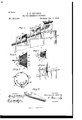
- My invention is in the nature of an improved gravel screening machine adapted to take a mixture of gravel, sand, and dirt, and separate therefrom the gravel, wash it, and divide it into as many grades of difierent sizes as may be desired. It consists in the peculiar construction and arrangement of parts which I will now proceed to fully describe with reference to the drawings, in which Figure 1 is a side elevation of the machine showing a series of chutes with two screens for the separation of the gravel into grades of two different sizes, but which screens and chutes may be increased to separate the gravel into any number of grades.
- Fig. 2 is a detail side view of one of the conical open-ended screens showing in dotted lines the various angles which its sides may sustain to the carrying shaft.
- Fig. 1 is a side elevation of the machine showing a series of chutes with two screens for the separation of the gravel into grades of two different sizes, but which screens and chutes may be increased to separate the gravel into any number of grades.
- Fig. 2 is a detail side view of one of the conical open-ended screens
- FIG. 3 is a side view of the skeleton frame of the conical screen.
- Fig.4. shows an extreme modification of the screen showing a cone of very large base and slight altitude.
- Fig. 5 is a detail in perspective of one of the chutes, and
- Fig. 6 is an end view of one of the screens showing position of spray pipe.
- A is a hopper supported by any suitable frame.
- the hopper is V-shaped on all of its four sides into which it is calculated to deposite sand, gravel, and other material either dry or by any process, or mixed with water as by the process of sluicing.
- B is a V-shaped chute, one end of which is fitted to the bottom and sides of the hopper, and for support at that end is fastened to the hopper.
- Said chute is for the purpose of receiving the material and water from the lower end of the hopper, and to conduct said material and water and deposit the same onto the inside of a hollow conical shaped revolving screen, Ethrough which the water and finer grades of material pass into the half circular chute, Iin the upper end of which the screen E revolves, but does not rest upon the chute, being supported by frames G G, or any other Serial No. 425,637. (No model.)
- the chute may be supported by the same frame or any other support, the object being simply to support and hold firmly in place the screen and chutes in such a manner as to allow the screen to revolve freely in close proximity to, but not in contact with the chute, the open end of the screen projecting a little outside of the upper end of the chute to allow the material that is too coarse to go through the meshes of the screen to be deposited outside of the upper end of the chute into any desired receptacle.
- the conical open ended screen supported at one end on its shaft receives in its open end one chute, and in turn is itself partially surrounded at its other or smaller end by the next lower chute.
- the chute I is made semi-circular in cross section, and its upper end is flanged at f (see Fig. 5) to enable it to closely approach and partially encircle the screen so as to prevent the water and material that has passed through the screen from flowing back out of the chute.
- This chute is for the purpose of receiving the water and material that passes through the screen, and conducting and depositing the same into the next screen and chute of the series where the material undergoes the same treatment as in the preceding screen, and so on as many times as it is desired to separate the material.
- the screen is attached to a shaft F, which is supported by the frame G G, and is-revolved by means of a belt over a band wheel H, or by means of gear wheels attached to any part of the shaft F, or by knucklejoints as occasion requires. Any kind of motive power may be used.
- the size of the mesh of the different screens is governed by the size of the material desired. I also find that to properly treat the different grades of material it requires the shape of the screen to be varied. Consequently I do not Wish to confine myself to any particular angle or flare of the screen between the points ac, and bb shown in Fig. 2.
- FIG. 3 shows the construction of the screens, and the manner of attaching them to the shaft.
- A is a shaft with a shoulder-B on which is fitted a metal head 0, which is held in.place by a nut on the end of the shaft.
- the outer edge of the metal head is beveled to any angle to suit the shape of the screen desired.
- notches n are cut, and bolts D are set with nuts on them.
- EE are twin rods which are clamped together upon opposite sides of the wire netting by the bolt D at the inner ends, and short bolt 6 at the outer end.
- the open ended conical screen composed of a shaft with a head O rigidly fastened to the shaft, and having a beveled and notched edge, the wire netting and the clamp rods or ribs E E bolted together upon opposite sides of the wire netting and bolted down into the notches at one end and diverging therefrom, substantially as shown and described.
- the screen E consisting of a conical wire netting with head 0 at its smaller end combined with and supported at said end upon the shaft E which terminates at said head leaving said screen entirely unobstructed and open at its outer and larger end, substantially as shown and described.
Landscapes
- Engineering & Computer Science (AREA)
- Mechanical Engineering (AREA)
- Separation Of Solids By Using Liquids Or Pneumatic Power (AREA)
Description
(No Model.)
P. T. GILBERT.
. GRAVEL SUREENING MACHINE.
N0. 489,380. Patented Jan. 3, 1893.
E JE e E e I a? is F M I T ATTORNEYS "m: oams vsvzns co. vncmxumu, wusnmomn. n, c.
Unirrnn fireflies PATENT UFFICE.
FRANKLIN T. GILBERT, OF WALLA WALLA, ASSIGNOR TO SUSIE M. R. GILBERT, OF SEATTLE, WASHINGTON.
GRAVEL-SCREENING MACHINE.
SPECIFICATION forming part of Letters Patent No. 489,380, dated January 3, 1893.
Application filed March 19, 1892- To all whom it may concern:
Be it. known that I, FRANKLIN T. GILBERT, residing at Walla Walla, in the county of Walla Walla and State of Washington, have invented a new and useful Improvement in Gravel-Screening Machines, of which the following is a specification.
My invention is in the nature of an improved gravel screening machine adapted to take a mixture of gravel, sand, and dirt, and separate therefrom the gravel, wash it, and divide it into as many grades of difierent sizes as may be desired. It consists in the peculiar construction and arrangement of parts which I will now proceed to fully describe with reference to the drawings, in which Figure 1 is a side elevation of the machine showing a series of chutes with two screens for the separation of the gravel into grades of two different sizes, but which screens and chutes may be increased to separate the gravel into any number of grades. Fig. 2 is a detail side view of one of the conical open-ended screens showing in dotted lines the various angles which its sides may sustain to the carrying shaft. Fig. 3 is a side view of the skeleton frame of the conical screen. Fig.4.shows an extreme modification of the screen showing a cone of very large base and slight altitude. Fig. 5 is a detail in perspective of one of the chutes, and Fig. 6 is an end view of one of the screens showing position of spray pipe.
A is a hopper supported by any suitable frame. The hopper is V-shaped on all of its four sides into which it is calculated to deposite sand, gravel, and other material either dry or by any process, or mixed with water as by the process of sluicing.
B is a V-shaped chute, one end of which is fitted to the bottom and sides of the hopper, and for support at that end is fastened to the hopper. Said chute is for the purpose of receiving the material and water from the lower end of the hopper, and to conduct said material and water and deposit the same onto the inside of a hollow conical shaped revolving screen, Ethrough which the water and finer grades of material pass into the half circular chute, Iin the upper end of which the screen E revolves, but does not rest upon the chute, being supported by frames G G, or any other Serial No. 425,637. (No model.)
suitable support. The chute may be supported by the same frame or any other support, the object being simply to support and hold firmly in place the screen and chutes in such a manner as to allow the screen to revolve freely in close proximity to, but not in contact with the chute, the open end of the screen projecting a little outside of the upper end of the chute to allow the material that is too coarse to go through the meshes of the screen to be deposited outside of the upper end of the chute into any desired receptacle.
The conical open ended screen supported at one end on its shaft receives in its open end one chute, and in turn is itself partially surrounded at its other or smaller end by the next lower chute.
The chute I is made semi-circular in cross section, and its upper end is flanged at f (see Fig. 5) to enable it to closely approach and partially encircle the screen so as to prevent the water and material that has passed through the screen from flowing back out of the chute. This chute is for the purpose of receiving the water and material that passes through the screen, and conducting and depositing the same into the next screen and chute of the series where the material undergoes the same treatment as in the preceding screen, and so on as many times as it is desired to separate the material.
The screen is attached to a shaft F, which is supported by the frame G G, and is-revolved by means of a belt over a band wheel H, or by means of gear wheels attached to any part of the shaft F, or by knucklejoints as occasion requires. Any kind of motive power may be used. The size of the mesh of the different screens is governed by the size of the material desired. I also find that to properly treat the different grades of material it requires the shape of the screen to be varied. Consequently I do not Wish to confine myself to any particular angle or flare of the screen between the points ac, and bb shown in Fig. 2.
At E Fig. 2, and 0, Fig. 4., there are represented the two extremes in the angle or flare which I may use in the construction of my screens, and these also give an idea of the different positions they will assume in rela- I introduce a sheet of water inside of the screens E E through which it passes into the upper end of the chutes II. The materialin passing down is obliged to pass through this sheet of water, and is thereby washed clean.
Fig. 3 shows the construction of the screens, and the manner of attaching them to the shaft. A is a shaft with a shoulder-B on which is fitted a metal head 0, which is held in.place by a nut on the end of the shaft. The outer edge of the metal head is beveled to any angle to suit the shape of the screen desired. In the face of the bevel at proper distances notches n are cut, and bolts D are set with nuts on them. EE are twin rods which are clamped together upon opposite sides of the wire netting by the bolt D at the inner ends, and short bolt 6 at the outer end. On the face of the bevel is placed the screen through which the bolts must pass, with a rod E on the outside, and its companion E on the inside, and both resting in notches it. 'These rods are tightened upon the screen by bolts 9, and at the same time the screen and rods are fastened to the head C by turning the nuts D down to place in the head which also looks the rods E E in the notches so as to connect them Stifliy against torsional strain, leaving the outer end of the screen entirely open.
In defining the relation of my present invention to those shown in two other prior applications for patents, Serial Nos. 418,712 and 424,592, filed respectively January 20, 1892 and March 11, 1892,I would state that I make no claim here to anything shown in said applications.
Having thus described my invention, what I claim and desire to secure by Letters Patent 1s- 1. The combination of a revolving shaft, a conical open ended screen arranged upon one end of the shaft, and supported thereupon by its smaller end or head, and having its larger end open and projecting outwardly, a delivery chute discharging into the larger open end of the screen, and a receiving chute arranged upon the outside and below or partly around it, substantially as shown and described.
2. The open ended conical screen composed of a shaft with a head O rigidly fastened to the shaft, and having a beveled and notched edge, the wire netting and the clamp rods or ribs E E bolted together upon opposite sides of the wire netting and bolted down into the notches at one end and diverging therefrom, substantially as shown and described.
3. The screen E, consisting of a conical wire netting with head 0 at its smaller end combined with and supported at said end upon the shaft E which terminates at said head leaving said screen entirely unobstructed and open at its outer and larger end, substantially as shown and described.
4. The combination with the chutes I land the screen E; of the water pipe L having a curved cross pipe at its end with spray openings arranged inside the screen and between the chutes, substantially as shown and described.
FRANKLIN T. GILBERT.
Witnesses:
EDW. IV. BYRN, SoLoN C. KEMON.
Publications (1)
| Publication Number | Publication Date |
|---|---|
| US489380A true US489380A (en) | 1893-01-03 |
Family
ID=2558226
Family Applications (1)
| Application Number | Title | Priority Date | Filing Date |
|---|---|---|---|
| US489380D Expired - Lifetime US489380A (en) | Gravel-screening machine |
Country Status (1)
| Country | Link |
|---|---|
| US (1) | US489380A (en) |
-
0
- US US489380D patent/US489380A/en not_active Expired - Lifetime
Similar Documents
| Publication | Publication Date | Title |
|---|---|---|
| US616033A (en) | sturcke | |
| US3530986A (en) | Screen apparatus | |
| DE9015363U1 (en) | Device for material dispersion | |
| US1103167A (en) | Screen. | |
| US2992740A (en) | Ore classifier | |
| US1108542A (en) | Centrifugal sand screening and separating machine. | |
| US973149A (en) | Revoluble sizing-screen. | |
| US753440A (en) | Coal separator and washer | |
| US474662A (en) | Gravel-screen | |
| US501898A (en) | Bolting-reel | |
| US449417A (en) | Sand and gravel cleaning machine | |
| US881207A (en) | Disintegrating, washing, and screening machine. | |
| US1212179A (en) | Revolving screen and method of screening. | |
| US332250A (en) | Scalping-machine | |
| GB356913A (en) | Improved rotary apparatus for washing gravel, sand and other materials | |
| US333398A (en) | Centrifugal reel | |
| DE10404C (en) | Cleaning and sorting machine for Sitat, Griese and the like | |
| US138823A (en) | Improvement in rotary sieves | |
| US447029A (en) | Concentrating apparatus | |
| US1199300A (en) | Wet-screen. | |
| US417630A (en) | Rotary bolt | |
| US489378A (en) | Gravel washer and separator | |
| US463482A (en) | clark | |
| US468134A (en) | Gravel-screening machine | |
| US509706A (en) | Sand-screen |