US4890973A - Universal fork-supported push-pull slip sheet handling attachment for forklift trucks - Google Patents
Universal fork-supported push-pull slip sheet handling attachment for forklift trucks Download PDFInfo
- Publication number
- US4890973A US4890973A US07/123,536 US12353687A US4890973A US 4890973 A US4890973 A US 4890973A US 12353687 A US12353687 A US 12353687A US 4890973 A US4890973 A US 4890973A
- Authority
- US
- United States
- Prior art keywords
- base frame
- fork
- platen
- attachment
- forks
- Prior art date
- Legal status (The legal status is an assumption and is not a legal conclusion. Google has not performed a legal analysis and makes no representation as to the accuracy of the status listed.)
- Expired - Lifetime
Links
- 125000006850 spacer group Chemical group 0.000 claims description 32
- 230000000670 limiting effect Effects 0.000 claims description 2
- 230000007246 mechanism Effects 0.000 description 21
- 230000005484 gravity Effects 0.000 description 12
- 238000010276 construction Methods 0.000 description 11
- 238000005452 bending Methods 0.000 description 8
- 238000003780 insertion Methods 0.000 description 5
- 230000037431 insertion Effects 0.000 description 5
- 230000004048 modification Effects 0.000 description 4
- 238000012986 modification Methods 0.000 description 4
- 230000003014 reinforcing effect Effects 0.000 description 4
- 238000003466 welding Methods 0.000 description 4
- 238000013461 design Methods 0.000 description 3
- 239000012530 fluid Substances 0.000 description 3
- 238000000034 method Methods 0.000 description 3
- 230000036961 partial effect Effects 0.000 description 3
- 241000755266 Kathetostoma giganteum Species 0.000 description 2
- 229910000831 Steel Inorganic materials 0.000 description 2
- 230000006978 adaptation Effects 0.000 description 2
- 230000009977 dual effect Effects 0.000 description 2
- 230000000694 effects Effects 0.000 description 2
- 238000009434 installation Methods 0.000 description 2
- 230000008569 process Effects 0.000 description 2
- 230000009467 reduction Effects 0.000 description 2
- 230000002829 reductive effect Effects 0.000 description 2
- 230000000717 retained effect Effects 0.000 description 2
- 230000000087 stabilizing effect Effects 0.000 description 2
- 239000010959 steel Substances 0.000 description 2
- 239000003351 stiffener Substances 0.000 description 2
- 229910052782 aluminium Inorganic materials 0.000 description 1
- XAGFODPZIPBFFR-UHFFFAOYSA-N aluminium Chemical compound [Al] XAGFODPZIPBFFR-UHFFFAOYSA-N 0.000 description 1
- 238000013459 approach Methods 0.000 description 1
- 230000008859 change Effects 0.000 description 1
- 238000006243 chemical reaction Methods 0.000 description 1
- 230000001143 conditioned effect Effects 0.000 description 1
- 230000008878 coupling Effects 0.000 description 1
- 238000010168 coupling process Methods 0.000 description 1
- 238000005859 coupling reaction Methods 0.000 description 1
- 230000003028 elevating effect Effects 0.000 description 1
- 230000002708 enhancing effect Effects 0.000 description 1
- 239000000835 fiber Substances 0.000 description 1
- 239000000463 material Substances 0.000 description 1
- 229910052751 metal Inorganic materials 0.000 description 1
- 239000002184 metal Substances 0.000 description 1
- 230000002787 reinforcement Effects 0.000 description 1
- 230000000284 resting effect Effects 0.000 description 1
- 230000002441 reversible effect Effects 0.000 description 1
- 239000007787 solid Substances 0.000 description 1
- 238000012360 testing method Methods 0.000 description 1
- 230000000007 visual effect Effects 0.000 description 1
- 239000013585 weight reducing agent Substances 0.000 description 1
- 239000002023 wood Substances 0.000 description 1
Images


Classifications
-
- B—PERFORMING OPERATIONS; TRANSPORTING
- B66—HOISTING; LIFTING; HAULING
- B66F—HOISTING, LIFTING, HAULING OR PUSHING, NOT OTHERWISE PROVIDED FOR, e.g. DEVICES WHICH APPLY A LIFTING OR PUSHING FORCE DIRECTLY TO THE SURFACE OF A LOAD
- B66F9/00—Devices for lifting or lowering bulky or heavy goods for loading or unloading purposes
- B66F9/06—Devices for lifting or lowering bulky or heavy goods for loading or unloading purposes movable, with their loads, on wheels or the like, e.g. fork-lift trucks
- B66F9/075—Constructional features or details
- B66F9/12—Platforms; Forks; Other load supporting or gripping members
- B66F9/19—Additional means for facilitating unloading
- B66F9/195—Additional means for facilitating unloading for pushing the load
Definitions
- the present invention relates to push-pull slip sheet handling attachments for forklift trucks and especially to such attachments that are fork-supported.
- a forklift truck equipped with a push-pull attachment and wide forks for handling slip sheets as described is shown, for example, in Brudi U.S. Pat. No. 3,640,414.
- Low-lift, walkie-type vehicles normally used for handling pallets but adapted to handling slip sheets by the addition of wide forks or platens and push-pull mechanisms are shown, for example, in Rocco U.S. Pat. No. 4,065,012, Olson U.S. Pat. No. 4,274,794 and Frees U.S. Pat. No. 4,300,867.
- slip sheet handling attachments which can be quickly attached to and detached from forklift trucks and low-lift vehicles while the conventional narrow pallet-handling forks remain on the vehicle.
- DF attachment One such attachment for a forklift truck has been developed and marketed by DF Industries, Inc., of Alpharetta, Ga.
- This unit includes a single wide platen connected to an upright rear frame.
- the frame mounts a push-pull assembly including a hydraulically powered horizontal pantograph mechanism which moves a push plate with slip sheet gripping jaws in and out over the platen.
- the entire unit rests on and is fully supported on the upper surfaces of the conventional narrow forks.
- the rear frame connects directly to the forks by connecting pins which extend behind the upright portions of the fork heels to retain the attachment on the truck.
- the DF attachment has a self-contained hydraulic power unit which draws electric power from the lift truck.
- the attachment is quite lightweight, being made mostly of aluminum, but because of this is vulnerable to damage from the abuse to which such attachments are commonly subjected in normal industrial use.
- One version of the DF attachment is adapted for mounting on a walkie or hand jack.
- This version adds to the forklift version a powered push-pull cylinder which connects the entire unit to the low-lift vehicle frame so that the entire unit, including push-pull frame and platen, can extend and retract on the conventional forks of such vehicles.
- the platen tips down to ground level to enable the gripping jaws of the push plate to grip a ground-level slip sheet and pull it onto the platen, after which retraction of the push-pull cylinder pulls the unit onto the forks.
- Cascade Corporation of Portland, Oreg. has also marketed a push-pull slip sheet attachment (Cascade attachment) which can be mounted on a forklift truck without removing the conventional narrow pallet forks.
- Cascade attachment An attachment substantially similar to the Cascade attachment as marketed is shown in Farmer, et al. U.S. Pat. No. 4,482,286 (Farmer patent), and unless otherwise noted, both are referred to herein as the Cascade attachment.
- the attachment of the Farmer patent connects to the lower cross bar
- the Cascade attachment as marketed connects to both the upper and lower cross bars, of an Industrial Truck Association (ITA) standardized lift truck carriage.
- ITA Industrial Truck Association
- the Cascade attachment has dual platens, which, like the single platen of the DF attachment, are vertically supported on the forks, at least when the platens are loaded.
- the rear frame of the Cascade attachment nests between the fork uprights, rather than in front of them as in the DF attachment.
- the Cascade attachment unlike the DF attachment, does not have a self-contained hydraulic power unit. Instead, like other push-pull attachments, it takes its hydraulic power from the lift truck through hydraulic hoses, which supply a pair of push-pull cylinders and a pair of gripping jaw cylinders on the attachment.
- the Cascade attachment with its push-pull assembly fully retracted has substantially less fore and aft bulk or thickness than the DF attachment, and a center of gravity closer to the front wheels of a connected truck. Nevertheless, the Cascade attachment is considerably heavier than the DF attachment, primarily because of its nearly all-steel construction and its heavy frame design.
- the rated load capacity of most lift trucks is based on use of the truck with conventional narrow forks. It is measured as that load which the truck can handle at a distance of 24 inches from the outwardly facing surface of the fork upright portions with the conventional forks attached to the carriage.
- the net load capacity of the truck is reduced.
- the added weight of the attachment reduces the net load capacity of the truck.
- lift truck attachments because of their bulk, also reduce the net load capacity of a lift truck by shifting the center of gravity of a load carried by the truck forward from where it would be if handled solely by the truck's conventional forks. This center of gravity-shifting of the load by the attachment is referred to in the industry as the "lost load” or "effective thickness.”
- DF attachment incidentally avoids most platen bending problems through the use of fork-receiving pockets on the underside of the platens.
- the primary purpose of such fork pockets is to mount the attachment on the forks rather than on the ITA carriage.
- fork pockets cannot be designed to accomodate all such forks without adding excessive weight to the attachment.
- a disadvantage of prior fork-supported push-pull attachments of the type shown in the Farmer patent is that they can be attached only to lift trucks equipped with ITA lift carriages characterized by the types of upper and lower fork-connecting cross bars shown in such patent.
- the forks for an ITA carriage have hooks which hook to the upper and lower cross bars of the carriage.
- Other attachments, including push-pull attachments, for such a carriage typically include similar hooks for the same purpose.
- many forklift trucks, especially older ones do not use ITA lift carriages to connect the forks to the truck.
- an attachment of the DF type can be mounted on lift trucks having both ITA and pin-type carriages because the DF attachments connect to the forks not the carriage, the DF pin-type connector for this purpose has some serious disadvantages.
- the attachment When a DF type attachment is fitted to pin-type forks of a lift truck having a tilt mechanism, the attachment must be spaced a substantial distance in front of the fork uprights to clear the tilt mechanism. This spacing is accomplished by spacer bolts on the frame. These same spacer bolts are used to snug the fork connecting pins against the backs of the forks on both ITA and pin-type carriages, both of which commonly carry forks of different thicknesses.
- the connecting means for connecting prior fork-supported attachments to lift trucks have been subject to damage and breakage under normal industrial use.
- One problem is that the quick-connect elements of such connecting means have been located in close proximity to the forks, subjecting them to fork impact as the operator attempts to insert the forks beneath the platens during installation of the attachment on a truck.
- Some such connecting means have also included elements which become broken or damaged by catching on cracks or floor protrusions such as loading ramps as the fork truck is driven over them with the load positioned close to the floor as is commonly done for safety.
- Prior fork-supported push-pull attachments are not self-supporting in a stable free-standing position on a level ground surface when detached from a lift truck such that the forks of a lift truck can be inserted beneath and withdrawn from beneath the attachment while in such position.
- a pivoting hook-type connector swings down and forward to a frame support position extending below the lower limits of the forks so that, theoretically, the lower connecting hooks and tips of the platens support the attachment in a free-standing position on level ground when detached from a lift truck.
- the attachment when thus supported with its push-pull mechanism retracted, the attachment is unstable because its center of gravity is so far above the platens and so close to the rear of the attachment in relation to the rear support point provided by the hooks that the attachment will tend to tip over backward with a small push in that direction. This is obviously undesirable for safety and other reasons in an industrial environment.
- a quick-mounting fork-supported slip sheet handling attachment for a forklift truck which (a) minimizes the reduction in rated load capacity of the truck; (b) is easily adaptable for connection to trucks having both ITA and pin-type lift carriages; (c) has quick-connect means capable of withstanding the rigors of industrial use with all types of forks in common use; (d) has platens that are lightweight yet strong to resist permanent bending under normal industrial use; (e) is stable in a self-supporting, free-standing mode with or without the platens and irrespective of push plate position; and (f) can easily be attached to a lift truck from its free-standing position.
- Primary objectives of the present invention are to provide a new and improved fork-supported slip sheet handling attachment for a forklift truck that:
- (2) is adapted for connection to lift trucks having both pin-type and ITA-type fork carriages and forks of different sizes and shapes;
- a lightweight but strong upright space-type base frame characterized by an open flexible framework including a pair of upright, transversely spaced apart side frame members which can be interconnected by a single cross frame member.
- a load-engaging platen which also structurally interconnects the lower ends of the upright side frame members to strengthen and help stiffen the open framework of the base frame;
- a base frame with side frame members which extend outside the forks and straddle the fork uprights on an ITA-type carriage to enable some lateral adjustment of the forks inwardly of the side frame members and centering of them beneath the platens for optimum underlying fork-support for the platen means;
- a fork-connecting means carried by the base frame for connecting the frame to the fork upright portions, with the fork-engaging surfaces of the connecting means moving in a reference plane of the rear surfaces of the fork uprights to adapt the attachment for mounting to forks of different thickness, heel bend and ITA hook configurations and to either pin-type or ITA-type forks;
- a base frame, platen means and fork-connecting means which cooperate to make the attachment lie reasonably flat on the top load supporting surfaces of typical industrial forks, even though such surfaces may intersect their respective fork upright portions at different angles and at greater than 90 degrees;
- a base frame support means for supporting the base frame of the attachment in a stable, elevated, free-standing position on a reasonably flat, level floor when removed from a lift truck, to facilitate mounting of the attachment on and its removal from the truck;
- a frame support means as aforesaid which in its active frame-supporting position has a frame-supporting portion extending rearwardly of the aforementioned reference plane for optimum stability when the frame is in its free-standing position;
- a frame support means as aforesaid which cooperates with the aforementioned forward continuations of the side frame members to provide a stable support for the base frame even with the platen means removed from the frame;
- a locking means which may include a vernier adjustment feature, for securely locking the fork-connecting means and frame support means in their active and inactive positions regardless of variations in fork thickness, fork heel configuration and ITA fork hook configuration;
- a platen stiffening means which cooperates with the two side frame members to stiffen the platens and which can be added as required to suitably stiffen the platens and minimize the possibility of permanent platen bending when lifting loads on the tips of the platens;
- An alternative form of the invention incorporates many of the foregoing features, particularly the lightweight, compliant frame of the primary embodiment, but is designed for mounting to either ITA-type or pin-type forks without modification of the attachment.
- This alternative while still attaching to the forks, has a base frame which mounts in front of the fork uprights, and a simplified means for mounting the platen means directly to a bottom cross member of the base frame for weight reduction.
- This alternative may also include a modified fork-connecting means comprising a transversely movable connecting pin for engaging a rear surface of a fork upriqht, with the pin mounted on a vertically adjustable slide member carried by the base frame.
- the base frame may eliminate the forwardly projecting lower side frame portions, or ribs, and the combination support feet and fork connectors, replacing them instead with simple skid plates mounted to the bottom of the platen means for supporting the attachment when dismounted from the forks and for rigidifying the platen means.
- FIG. 1 is a perspective view of an attachment in accordance with the invention as viewed from the rear and above the attachment, with the push plate fully extended;
- FIG. 2 is a side elevational view of the attachment of FIG. 1 on a lift truck with an ITA carriage and with the push-pull assembly of the attachment removed;
- FIG. 3 is a front elevational view of the base frame portion of the attachment shown connected to the same lift truck as in FIG. 2, with the push-pull assembly of the attachment removed and the forks and platens sectioned about halfway along their length;
- FIG. 4 is an enlarged perspective view of the base frame portion of the attachment
- FIG. 5 is a bottom plan view of the attachment connected to an ITA carriage
- FIG. 6 is an enlarged rear perspective view of a lower frame portion of the attachment shown connected to an ITA carriage;
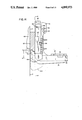
- FIG. 7 is an enlarged side elevational view of generally the same lower frame portion of the attachment as shown in FIG. 6;
- FIG. 8 is a side elevational view of the full attachment in its self-supporting free-standing mode and with its push-pull mechanism retracted;
- FIG. 9 is a view similar to FIG. 8 but with the platen means removed from the attachment;
- FIG. 10 is a view similar to FIG. 5, but showing a modified platen construction
- FIG. 11 is a side elevation of the platen construction shown in FIG. 10;
- FIG. 12 is a side elevational view of a frame portion of the attachment with a slightly modified connector and shown mounted to one class of pin fork-type lift truck;
- FIG. 13 is a sectional view taken along the line 13--13 of FIG. 12;
- FIG. 14 is a view generally similar to FIG. 7 but showing the attachment with a modified forklift truck connecting means.
- FIG. 15 is a partial, foreshortened side elevational view of another modified form of attachment in accordance with the invention and shown mounted on the forward end of a lift truck;
- FIG. 16 is a foreshortened bottom plan view of the attachment of FIG. 15, on a reduced scale, shown mounted on a lift truck;
- FIG. 17 is a partial perspective view of the attachment of FIG. 15 and the fork portion of a lift truck being inserted beneath the attachment during mounting of the attachment on the forks;
- FIG. 18 is a partial front elevational view of the attachment of FIG. 15 mounted on a lift truck, with the platens of the attachment and the horizontal fork portions being shown in section, and with portions of the forks and base frame of the attachment being broken away for clarity; and
- FIG. 19 is an enlarged exploded perspective view of the fork-mounting portion of the attachment of FIG. 15
- FIG. 1 of the drawings what is now a preferred embodiment of the attachment of the present invention includes an upright base frame, indicated generally at 10, mounting at its lower end a platen means comprising a pair of thin plate-like platens 12, 13 and a yoke-like spacer plate 62 extending forwardly of base frame 10. Above the platen means the base frame mounts a push-pull assembly indicated generally at 14.
- the push-pull assembly includes an upright push plate 16 connected to the base frame by a powered lazy tong or pantograph linkage mechanism 18 for extending and retracting the push plate 16 over the platens from a retracted position adjacent the base frame as shown in FIG. 8 to an extended position adjacent the tips of the platens as shown in FIG. 1.
- the pantograph mechanism includes a single fluid power actuating cylinder 20 for extending and retracting the mechanism and thus the push plate 16. Although a pair of actuating cylinders could be used, the single cylinder 20 is preferred because it simplifies the pantograph linkage and the power distribution and control means (not shown), with resultant savings in weight and cost.
- the lower edge portion of the push plate carries a gripper jaw means, including a stationary lower gripper jaw 22 and a vertically movable upper gripping bar 24.
- the gripper bar 24 is operated by a pair of vertically disposed fluid power cylinders 26 and coacts with the gripper jaw 22 for selectively gripping and releasing a free edge of a slip sheet in a well-known manner.
- pantograph cylinder 20 and gripper jaw cylinders are typically powered by a source of pressure fluid on a connected lift truck through appropriate quick-coupled hydraulic hoses on the truck and attachment (not shown) in a well-known manner.
- the pantograph and jaw actuating means 26 can be electric actuators which draw electric power from the lift truck, also in a well-known manner.
- the pantograph mechanism and gripper jaw means are of conventional construction, well-known in the industry and are generally described in Brudi U.S. Pat. No. 3,640,414. Briefly, the forward ends of the two front regulator arms 19 of the pantograph mechanism ride up and down on low-friction slides 34 in upright guide channels 28 of the push plate 16 while two front push-pull arms 17 (only one being shown in FIG. 1) are pivoted at points 30 to lower portions of push plate 16. Similarly, the rear ends of two rear regulator arms 27 are connected to a cross bar 32 which rides on low friction slides 34 in guide channels 36 of the side frame members 38, 40 of the base frame. A pair of rear push-pull arms 29 are fixed to a spreader tube 42 which pivots on a cross frame shaft 44. Shaft 44 extends between and is secured to the transversely spaced side frame members 38, 40 by keeper pins 45 on both ends of the shaft. Thus, shaft 44 pivotally connects the rear push-pull arms 29 to the base frame.
- FIGS. 2-3 and 5-7 the described attachment is shown mounted on a forklift truck of a conventional type having a forwardly and rearwardly tiltable mast (not shown) mounting a lift carriage 46 which travels up and down on the mast.
- the carriage mounts an upper cross bar 48 having an upward projection 49 along its upper edge and a lower cross bar 50 having a downward projection 51 along its lower edge.
- These cross bars and the profile of the projections are configured, sized and spaced according to ITA standardization guidelines, and are referred to hereinafter as ITA bars and its carriage as an ITA carriage.
- a pair of typical, relatively narrow, pallet handling load-lifting forks 52 are mounted on the ITA carriage cross bars in a well-known manner.
- Such forks are generally right angular in shape, including generally horizontal load-engaging portions 53 and upright fork portions 54.
- the upright portions have integral downwardly projecting upper hooks 56 and integral upwardly projecting lower hooks 58 on their rear surfaces which interengage the upper and lower ITA bars, respectively, to secure the forks to the carriage in a well-known manner.
- Attachments other than the conventional narrow pallet forks 52 shown are commonly attached to the ITA bars of a lift carriage in the same manner as the forks or with quick lock-unlock bottom hooks.
- the preferred embodiment of the present invention unlike most slip sheet and other attachments, mounts on, is always fully supported on, and connects directly and firmly to, the conventional narrow lift truck forks 52 rather than to the ITA bars, adapting the attachment to be used readily with lift trucks having carriages which are not of the ITA type.
- the platens can be made of thin, lightweight sheets of material and need not have the inherent rigidity and therefore weight to support a load by themselves. Instead, the forks retain their full load-supporting function and transmit all loads to be handled by the lift truck directly to the lift carriage.
- the attachment is of substantially lighter weight than past and currently available attachments of its type without sacrificing strength, durability and rated load handling capacity. For example, a prototype of the attachment has been designed and successfully tested for a rated load capacity of 4,500 lbs. Previous attachments of its type and comparable size have had rated capacities of only 3,000 lbs. This attribute is achieved primarily by its unique base frame construction.
- the base frame is an open framework defined by thin transversely spaced apart upright side frame members 38, 40, interconnected by a cross frame shaft 44 (inside the tube 42). Shaft 44 extends through and is secured to lower side frame portions 70 by keeper pins 45 at both ends.
- the keeper pins are rigidly fixed to lower side frame portions 70 by bolts or other suitable means.
- shaft 44 in cooperation with keeper pins 45, keeps the side frame members parallel in all planes.
- a top cross frame member 60 which can be pinned or otherwise connected to side frame members 38, 40.
- the platen means including the two thin platens 12, 13 joined by the thicker spacer plate 62 at their inner rear ends.
- the spacer plate is not connected directly to the base frame 10 and does not protrude between the fork uprights 54 or side frame portions 70, as shown in FIG. 5. Instead, it is simply connected to the two platens 12, 13, serving as a spacer and stiffener to maintain a desired spacing, rigidity and horizontal flatness therebetween while adding minimal weight to the attachment.
- Plate 62 may be connected to the underside of platens 12, 13 by threaded fasteners, by welding, or by other suitable means.
- a rectangular bar or restrictor plate 64 depending from the underside of spacer plate 62 at its rear end serves as a visual aid or guide means to the forklift operator when inserting the forks beneath the platens and prevents fork insertion beneath the platens in that region which, if permitted, could cause improper mounting of the attachment on the forks.
- the shape of plate 62 can be modified as shown in FIGS. 10 and 11.
- Stiffening ribs 65 are affixed to the outer edges of plate 62 and extend parallel to the longitudinal axis of the platens.
- the outer margins of the platens can be stiffened by attaching ribs 66 to side frame portions 74.
- These stiffeners can be of rectangular cross section wedge-shaped pieces, as shown, or of other appropriate shapes. They can be affixed to the platens by welding as shown, by bolting, or by other appropriate means.
- the attachment can be equipped with a single thin, wide platen, in which case plate 62 would still be attached and retained beneath the single platen in the position shown in FIGS. 1 and 5.
- Each side frame member 38, 40 includes a thin, lightweight, fabricated upper section 68, which forms the guide channels 36 for the pantograph cross bar slides 34.
- Upper section 68 is welded to the stronger, solid rectangular lower section 70 mounting the pantograph pivot shaft 44.
- Lower sections 70 include forwardly projecting continuations or ribs 74 at their lower ends which mount the platens to the frame. Ribs 74 project beneath platens 12, 13 laterally outwardly of forks 52 (see FIG. 5), which support the platen means by engaging the platens between stiffening ribs 74 and stiffening plate 62. The platens are connected to the upper surfaces of ribs 74 by threaded fasteners, welding, or other appropriate attachment means. Each rib includes a laterally outwardly projecting support portion 76 to provide additional lateral stiffening of the platens.
- stiffening plate 62 serves as a platen spacer and has an important platen stiffening function, it does not connect the platens to the frame and is not itself connected to the frame except through the platens.
- the platen means and frame cooperate to form a unique, light, flexible but strong space frame structure.
- the upright members of this structure are the two side frame members 38, 40.
- the primary transverse members of this space frame structure are the platen means 12, 13, 62 as a unit acting as one cross member and the cross frame shaft 44 working with keeper pins 45 as a second cross member.
- Top cross member 60 of the frame is a redundant submember of such space frame with either one of the two mentioned primary cross members and therefore need not be rigidly attached to the side frame members 38, 40.
- the only purpose of cross member 60 is to maintain the two side frame members 38, 40 parallel when shaft 44 and pantograph mechanism 18 are not attached to the side frame members.
- the compliant and flexible nature of the described space frame structure allows the platen means to seat on and conform to a wide range of new or used forks on new or old forklift trucks.
- a fork When new, a fork usually forms an angle of 90° between the upper surface of its generally horizontal load-supporting tine portion 53 and its upright shank portion 54. Further, the horizontal fork portions 53 are generally 90° to the face of the carriage ITA bars and parallel to each other. After typical use, however, this is rarely the case. Yet ideally the platens should lie directly on the fork load support surfaces with no appreciable gap.
- the platens With the flexible and compliant nature of the space frame described and the manner by which it is connected to the truck, the platens will accommodate a wide range of fork conditions and geometries and still seat on the forks with minimal gaps. Further, because of the torsion bar effect of the platen means, the space frame assembly has been found from tests to be capable of absorbing and dissipating energy from high-velocity direct impacts with the platen means at various angles without structural deformation.
- each lower side frame portion 70 where it curves to form rib 74, is substantially thicker than the corresponding fork 52 at its bend or heel, and therefore provides substantial bending strength at this point, equaling or exceeding that of the forks.
- Ribs 74 also provide stabilizing supports for the attachment when it is detached from a lift truck and the platens are removed from the ribs, as shown in FIG. 9 and described in more detail shortly.
- the length of ribs 74 can be varied depending on needs and flex characteristics of the platens. With very flexible platens, the ribs can be lengthened to stiffen forward portions of the platens, as shown in FIG. 10.
- the side frame members 38, 40 are relatively wide in a fore and aft direction and laterally thin, enhancing their strength-to-weight ratio and providing the frame with its greatest strength in the direction where it is most needed, that is, in the push-pull direction of the attachment.
- the base frame straddles and lies in front of the pair of fork uprights 54 when mounted on a lift truck having an ITA carriage, as best shown in FIGS. 2 and 3. That is, the top cross frame member 60 overlies the fork uprights, the side frame members 38, 40 extend along the outside of such uprights, spreader tube 42 and pivot shaft 44 are in front of such uprights, and the rear surfaces of the side frame members lie substantially in the same vertical plane P (FIG. 2) as the rear surfaces of the fork uprights 54 and the front faces of ITA bars 48, 50 of the lift truck carriage.
- This nesting of the fork uprights inside the base frame coupled with the exceptionally lightweight construction of the frame, maximizes the net load capacity of a lift truck with the attachment installed, an important consideration in lift truck attachment design.
- the net load capacity of a lift truck with an attachment is a function of the attachment's effective thickness or lost load, its weight, and the location of its center of mass or gravity. Effective thickness is the minimum distance from the lift truck carriage face to the rear face of the load, which under ideal conditions is also the front face of the attachment's push plate when retracted. In this embodiment, this distance depends only on the fore and aft width of the base frame and the thickness of the push plate. Both of these dimensions are minimal in the present attachment. Obviously, the heavier and thicker the attachment and the greater the distance from the truck carriage face to its center of gravity, the less will be the net load capacity of the lift truck with the attachment in place.
- the present attachment because of its light weight and small effective thickness, provides a substantially greater net load capacity on a given lift truck than prior fork-mounted slip sheet attachments.
- the fork-connecting means of the attachment include fork-engaging means which extend behind the fork uprights 54 and engage the bottom surfaces 59 of the lower fork hooks 58 and rear surfaces of the fork uprights.
- the fork-connecting means cooperate with the frame lower side portions 70 and platen means to prevent any significant movement of the attachment on the forks in all but the vertical direction.
- the forks prevent movement in the vertical direction.
- the connecting means includes a pair of fork connectors, one carried on the outside of each lower side frame portion 70.
- Each connector includes a J-shaped slide plate 80, slidable vertically along the outside surface of lower side frame portion 70 within a slideway sleeve 82.
- the upper end of slide plate 80 includes a stop pin 84 which abuts the top of sleeve 82 to limit downward travel of the slide plate.
- slide plate 80 defines a frame support foot 86.
- the foot projects rearwardly from reference plane P to provide a means for supporting the rear of the attachment in an elevated self-supporting position with respect to a generally horizontal ground surface G when the attachment is removed from a lift truck, as shown in FIGS. 8 and 9.
- a fork-connecting block 88 Projecting laterally inward behind the heel of the fork from the inner surface of foot 86 is a fork-connecting block 88 providing the fork-engaging means.
- Block 88 has a fork-engaging front edge 90 which is constrained to move in the reference plane P of the rear frame and fork upright surfaces. It moves between a raised fork-engaging position U and a lowered fork-release position D shown in FIG. 7.
- edge 90 engages the rear surface of the adjacent fork upright 54 and the lowest surface 59 of the lower fork hook 58.
- fork-engaging edge 90 is disengaged from the rear surface of the fork and the lower fork hook.
- block 88 is spaced well below the bottom surface of the fork. This enables easy removal of the attachment from the lift truck by simply lifting the fork until its bottom surface clears the top of block 86 and then withdrawing the fork by backing the lift truck.
- the attachment when free-standing can easily be engaged by the forks.
- connecting block 88 moves from its fork-engaging position U to its fork-release position D
- frame support foot 86 moves from a raised, inactive position to its lowered, frame-supporting position shown in phantom in FIGS. 2 and 7. This feature enables the attachment to be disconnected from the lift truck and conditioned for free-standing self-support with a single manipulation of each connector.
- means are provided for locking the fork-connecting block 88 in its fork-engaging and fork-release positions.
- the same means selectively lock support foot 86 in its inactive and active frame-supporting positions.
- Such locking means include a row of vertical pin holes 92 extending through each sleeve 82 and corresponding pin holes (not shown) through lower frame section 70 aligned with holes 92.
- Another corresponding row of pin holes 93 extends through the slide plate 80, but at a slightly different spacing between holes than provided in the associated sleeve 82 and side frame portion 70. This provides, in effect, a vernier-type pin locking feature which employs a quick connect-disconnect ball detent pull pin 94.
- slide plate 80 is lifted by hand until the fork-engaging edge 90 of connecting block 88 engages bottom surface 59 of lower fork hook 58 simultaneously with engagement of the rear surface of fork upright 54, which is in plane P.
- pull pin 94 is inserted in the one of pin holes 92 which is most nearly aligned with a corresponding pin hole 93 of slide member 80.
- pull pin 94 is pulled from its pin hole to release the slide member and drop foot 86 to a frame-supporting position, wherein pin 84 abuts the top of sleeve 82, thereby also releasing fork-connecting block 88 from the fork.
- pull pin 94 is reinserted in the one of pin holes 92 then aligned with one of the corresponding pin holes 93 in slide plate 80 to lock the support foot in its frame-supporting position and the fork-connecting block 88 in its fork-release position.
- This vernier-type locking feature thus adapts the fork connector means to forks of different thicknesses and configurations at the fork heel.
- the fork-connecting means is adaptable to forks of widely varying widths, thicknesses, heel curvatures, lower fork hook geometries and hook weld styles. As will be described in more detail shortly, this feature also adapts the attachment for connection to both pin-type forks, shown in FIG. 12, and the ITA forks shown in FIGS. 2, 3, 5, 6 and 7.
- Slide plate 80 has several additional notable features. As shown in FIG. 7, the centerline of holes 93 in slide plate 80 is coincident with the centerline of holes 92 in sleeve 82 and with the edge surface 81 of slide plate 80 so that pin 94 cannot be misplaced above the row of holes 93. Without this feature, there would be a multiplicity of holes 92 in which pin 94 could be inserted without slider 80 being locked in its frame support position. Also, top surface 85 of slider 80 provides a hammer striking surface, should the slider become jammed in sleeve 82 for any reason. Foot 86 of the slider is also designed so as not to extend beyond the back plane C of the lower ITA bar to prevent interference with the fork lift carriage 46.
- the bottom of foot 86, the heel and toe of stiffening rib 74 and the lower back edge of block 88 have generous radii as shown in FIGS. 6 and 7 to allow the attachment to easily ride over truck loading ramp edges, warehouse floor cracks, and other floor obstructions which might otherwise damage the bottom of the attachment or the fork-connecting means.
- frame support foot 86 One important feature of the frame support foot 86 is the stability it gives the attachment when in a free-standing mode removed from the lift truck, as shown in FIGS. 8 and 9. Normally, when the attachment is removed from a truck, foot 86 supports the base frame at a sufficient elevation above the ground support surface G that the forks of a lift truck can be readily inserted beneath the platens 12, 13 for easy mounting and dismounting of the attachment.
- the base frame When the attachment is in its free-standing position, the base frame is tilted forward slightly, supported at its rear end on the generally lowest portion 91 of the lower edge of the foot and at its forward end by the tips of the platens 12, 13. This provides great stability against tipping in a forward direction, because the composite center of gravity CG of the lightweight attachment is located well forward of point 91 and well behind the tips of the platens. Even when the platens are removed from their supporting frame ribs 74 (FIG. 9), the attachment has good stability in any direction because it rests on the low point 91 of feet 86 and the forward ground contact point 95 of ribs 74, which act as stabilizing outriggers to resist forward tipping. In fact, points 91 and 95 are about equidistant from the projection on ground plane G of center of gravity CG with push plate 16 fully retracted, as indicated by the dimensions X-X in FIG. 9.
- FIG. 12 shows a fork-mounted slip sheet handling attachment for a forklift truck having one known configuration of pin-type forks and carriage.
- the configuration shown is probably the most difficult pin-type fork-carriage assembly on which to mount the subject push-pull attachment, and therefore illustrates the versatility of the attachment.
- the attachment is identical to the one shown in FIGS. 1-9, with two exceptions.
- First, its fork connecting means has a slightly modified slide plate 114 which adapts it for connection to a pin-type fork.
- a spacer assembly 124 also shown in FIG. 13, has been added to both lower side frame portions 70 to space these portions from the fork uprights 100 and to react upward platen tip loads against such uprights. Because of the identity of components in the attachments of FIGS. 1 and 12, the same reference numerals are used to identify corresponding components in both attachments.
- a basic difference between an ITA-type fork carriage as depicted in FIGS. 2, 3, 6 and 7 and the type of pin-type fork carriage shown in FIG. 12 is that in the latter the fork uprights 100 of forks 102 are pivotally mounted at their upper ends to a lift carriage 104 by a pin or shaft 106. This enables the forks to tilt in vertical planes independently of any tilting movement of lift carriage 104. In contrast, on the ITA carriage 46, forks 52 can be tilted only by tilting the mast which mounts the lift carriage.
- the pin 106 of the pin-type lift carriage is typically a shaft which extends from side to side of the carriage frame to pivotally mount both forks, which can be selectively positioned along the pin. Tilting movement of each fork is achieved through a pivoting roller mechanism, indicated generally at 108, mounted at the lower end of carriage 104.
- the roller mechanism mounts a roller 110 which bears against a lower rear surface of fork upright 100.
- Roller 110 is mounted between a pair of pivot arms 111. These arms are pivotally mounted at their inner ends at 112 for movement between a downwardly extending position shown in phantom in FIG. 12, and a forwardly projecting position shown in full lines in FIG. 12.
- roller 110 Forward pivotal extension of roller 110 pushes the fork upright forward about pin 106, tilting the tine of fork 102 up as shown in full lines.
- roller 110 pivots downward fork upright 100 moves by gravity to a position beyond the vertical, moving the tine of fork 102 to the downwardly tilted position shown in phantom.
- the mechanism for operating the roller is conventional and located in a housing within the confines of the carriage.
- carriage 104 is attached to a scissors mechanism on the lift truck, which raises and lowers the carriage while maintaining it in a vertical or other desired disposition.
- frame uprights 38, 40 do not straddle fork uprights 100. Instead they are disposed in front of such uprights although still laterally outward of them and straddling the tines of the forks. It is necessary to modify the slide plate of the fork-connecting means slightly to accommodate this difference.
- the connectinq means still includes the sleeve 82 and the vernier-type locking pin holes 92 and corresponding holes 93 in the lower portion 70 of each side frame member 38, 40.
- the slide member 114 of the connector although still J-shaped, must have a longer rearward projection of its foot portion 116 than with an ITA-type fork to enable its fork-connecting block 120 to reach behind the fork.
- the fork-engaging face 118 of block 120 like its ITA conterpart, engages the rear surface of the fork upright and moves in the reference plane P of such surface.
- the fork-engaging face 118 travels in the reference plane P. Face 118 always engages the rear surface of the fork in its fork-engaging position, regardless of the thickness of such fork or the configuration of its heel.
- the fork-connecting means for a pin-type fork is exactly the same in construction and operation as the corresponding connecting means previously described for an ITA-type fork.
- support foot 116 functions to support the attachment in a free-standing position in the same manner and with the same advantages as described with respect to the foot 86 of the attachment of FIGS. 1-11.
- the two slide plates 80 and 114 are interchangeable on the same attachment, adapting it for connection to both types of forks.
- Spacer assembly 124 is added to both side frame members 70 as shown in FIGS. 12 and 13.
- Spacer assembly 124 includes an angular slide 126, slidable in a sleeve 125.
- the sleeve has rows of aligned holes 128, 129.
- the slide has corresponding holes 130 of slightly different spacing.
- a pull pin 127 is inserted through an aligned pair of sleeve holes 128, 129 and an aligned one of slide holes 130 to lock slide in abutment against the front face of fork upright 100.
- the sleeve and slide holes thus provide a vernier-type adjustment similar to that of the fork-connecting means.
- Slide 126 can be suitably adjusted to space side frame members 70 from fork uprights 100 without tools. The cooperation between the platens on the forks and these two spacers tend to keep the fork-engaging face 118 against the back of the fork uprights 100.
- the fork tilt cylinder housing tends to protrude between the forks. Because the frame of the attachment is open at the back, it can be positioned further back on the forks than if the frame were closed as on prior fork mounted attachments. This maximizes the net load capacity of this type of forklift truck with the attachment.
- Another class of lift truck having pin-type forks employs a carriage which rides up and down a mast and tilts with the mast.
- the carriage incorporates a cross-carriage pin for mounting the forks but has a rigid heel bar instead of the described roller-type tilt mechanism.
- the forks tilt with and not relative to the carriage.
- spacer assembly 124 can be omitted.
- FIG. 14 shows the attachment of FIGS. 1-9, but with a frame support foot 140 which is a modification of foot 86 of FIG. 7.
- Foot 140 has no fork-engaging block 88. Instead, it has an upward projection 141 which complements the profile of the lower edge 51 of lower ITA bar 50 of an ITA carriage for engagement with such bar.
- the slide plate 142 which mounts foot 140 is otherwise shaped the same as slide plate 80.
- slide plates 142 and 80 are interchangeable on the same attachment 10 for the same purpose but connect the attachment to an ITA carriage in distinctly different ways.
- slide 80 with foot 86 and fork-connecting block 88 secure the attachment directly to the forks of any lift truck with an ITA carriage.
- slide 142 with foot 140 and top profile 141 secure the attachment only to the lower ITA bar of such a carriage.
- the connecting means of the attachment gives the attachment the versatility of being mountable on lift trucks with either ITA or pin-type carriages and being mountable on ITA carriages in two different ways, depending on user preference.
- its foot provides for stable self-support of the attachment in a free-standing position on a level support surface.
- FIGS. 15-19 show a modified embodiment of the invention mountable, without change, to forks of either the ITA type or of the pin type.
- the base frame is mounted in front of the fork uprights rather than straddling them but features a lightweight compliant framework similar to that of the preceding embodiments.
- the base frame 150 includes a pair of upright transversely spaced parallel side frame members 152, 154 interconnected by a top cross frame member 156 and a bottom cross frame member 158.
- a third, detachable intermediate cross frame member 160 spans the frame a short distance above the bottom cross frame member and serves as a pivot shaft for mounting the lower pivot tube 162 of the push-pull assembly of the attachment.
- a lift truck 164 (FIG. 15) includes a lift carriage 166 with top and bottom carriage crossbars 168, 170 of the ITA type for receiving the top and bottom hook portions 172, 173, respectively, of the upright fork portions 174 of a pair of lift forks 175, the horizontally extending portions of which are indicated at 176.
- the side frame members 152, 154 are of substantially the same construction as previously described with respect to the side frame members of the FIG. 1 embodiment.
- Each includes an upper frame section 178 joined to a lower frame section 180.
- the push-pull assembly of the FIG. 15 embodiment is of the same construction as the push-pull assembly of the FIG. 1 embodiment, the push-pull assembly of the FIG. 15 embodiment is neither shown nor described.
- the means by which the push-pull assembly of the FIG. 15 embodiment is attached to the base frame is the same as the means used in the FIG. 1 embodiment.
- a lower link portion 182 of the push-pull assembly at the base frame is shown in FIGS. 15 and 18 attached to the previously mentioned pivot tube 162.
- base frame 150 is essentially an open, rectangular framework of lightweight construction.
- each side frame member 152, 154 terminates at the upper surface of one of two platen plates 184, 186 which comprise the platen means.
- Platen plate 184 is attached directly to the underside of cross frame member 158 by four bolts 188.
- platen plate 186 spaced transversely from platen plate 184, is fastened directly to the underside of the same cross frame member 158 by four bolts 188.
- Cross frame member 158 is the sole means interconnecting the two platen plates 184, 186.
- each plate includes a rear extension 190 terminating at a rear edge 191 that is rearward of the rear edge 192 of the platen plate portions which extend laterally outwardly of the their respective side frame members.
- Rear extension 190 of each plate thus provides a means for attaching the plates to the base frame, in conjunction with bolts 188.
- each fastener 188 the two closest to each side frame member are flathead bolts countersunk in the lower surface of the platen plates.
- the other two bolts 188 of each platen plate located inwardly of a support rib 193 need not be flathead bolts nor countersunk and may be, for example, socket head bolts.
- the two bolts closest to the side frame member are countersunk to allow the horizontally extending fork portions 176 of the lift forks 174 to pass beneath the platens without obstruction outwardly of reinforcing ribs 193 and inwardly of skid plates 196, all as most clearly shown in FIG. 18.
- Reinforcing ribs 193 and skid plates 196 are affixed to the bottom surfaces of their respective platen plates 184, 186 as, for example, by welding.
- Each skid plate 196 is spaced transversely outwardly of its associated reinforcing rib 193 to provide a defined slot or tunnel 194 for insertion of and receiving the horizontally extending fork portions 176.
- the skid plate 196 and rib 193 for each platen plate together serve as guide means for insertion of the horizontal fork portions. They also provide reinforcement for the platen plates to help them resist bending.
- each skid plate 196 is of greater depth than the maximum thickness of the horizontally extending fork portion 176 and is also of at least slightly greater depth than its associated reinforcing rib 193.
- skid plates 196 support the attachment in a freestanding condition on a flat support surface and provide clearance for insertion of the horizontal fork portions 176 in the manner best shown in FIG. 17.
- Each skid plate 196 extends forwardly along its platen plate from the base frame and extends beneath the base frame in vertical alignment with the associated side frame member 152, 154, as will be most apparent from FIG. 18.
- Each skid plate terminates in a rear end spacer extension 198 beyond the rearmost surface of the base frame, terminating at a vertical rear edge surface 200 which abuts a front face 202 of the lift carriage means, or more specifically, the front face of the lower carriage crossbar 170.
- rear extension 198 provides a spacer means for spacing the base frame 150 a distance in front of the lift carriage sufficient to accommodate upright fork portions 174 of varying thicknesses behind the base frame.
- the spacer extension 198 ensures that regardless of the thickness of an upright fork portion 174, the rear surface 204 of each fork upright will always lie in the same generally vertical plane, which is generally coincident with the vertical plane 202 of the forwardmost faces of the carriage cross bars 168, 170. This is desirable, as will soon become apparent, because of the fork connecting means utilized by the attachment.
- each skid plate 196 may often engage a hard abrasive floor surface, particularly when the attachment is freestanding, and may also be slid along a floor surface, particularly when mounting or dismounting the attachment from a lift truck, the bottom surface of each skid plate is provided with a hardened metal wear plate insert 206 shown best in FIGS. 15 and 16.
- An angle bracket 208 is fastened to an inside face of each side frame member 152, 154 near the upper end of the lower section 180.
- the two angle brackets 208 are mounted at the same level vertically on the base frame and have rear edges 210 flush with the rear edge faces of the side frame members.
- the brackets 208 serve as stop means for limiting the forward movement of the upper end portions of the fork uprights 174 relative to the base frame to retain the fork uprights behind the base frame and prevent tilting of the base frame rearwardly beyond the fork uprights. This feature ensures proper orientation of the attachment and the forks, and also facilitates connection of the base frame to the forks of the lift truck.
- each side frame member is used to connect the base frame to the forks of the lift truck.
- Each fork connecting means includes a slide sleeve 214 attached to a lower outside surface of lower side frame section 180.
- a slide member 216 is slidable vertically within slide sleeve 214 and retained within the sleeve by a stop lug 218.
- Sleeve 214 includes a vertical row of pin holes 220 which are aligned with holes in the slide plate 216 and frame section 180 for receiving a locking pin 222 such as a ball lock pin. The pin is of length to extend through a selected one of the holes 220 and aligned holes in slide plate 216 and lower side frame section 180.
- slide plate 216 is attached to a rearwardly extending mounting plate 224 which extends rearwardly of the rear edge surface of the associated side frame member.
- a connecting pin carrier sleeve 226 is attached to the rear end of plate 224 with the axis of its opening extending horizontally in a direction transverse to the base frame.
- Pin carrier sleeve 226 mounts a connecting or latching pin 228 slidable within the sleeve between a retracted position as shown in FIG. 17 and an extended connecting position shown in FIGS. 16 and 18.
- the inner end 228a of pin 228 is circular but rearwardly of such end the pin has flattened sides 228b for sliding within the essentially square opening of carrier sleeve 226.
- the pin is thus prevented from sliding out of the sleeve 226 in an outward direction by the shoulders thus formed at inner end 228a.
- a snap ring 230 in a groove at the outer end of the pin prevents it from sliding from the carrier sleeve 226 in the inward direction.
- a leaf spring 232 extends rearwardly beneath plate 224 and through a slot 226a in the top of carrier sleeve 226.
- the spring is affixed at its other end by a bolt 234 to the inner underside of plate 224.
- the spring retains connecting pin 228 in its extended, connecting position. This is accomplished by providing an annular recess 228c in the surface of the pin into which leaf spring 232 drops to retain the pin in an extended position behind the rear surface of the fork upright.
- the outer end of the leaf spring is lifted from the pin recess 228c.
- the pin can then be slid to its retracted position from behind the fork upright.
- the fork-confronting flat surface of the pin lies in substantially the same vertical plane as the rear face of the fork upright (and front face of the lift carriage) to provide a snug connection.
- the lift truck operator inserts the horizontal fork portions 176 into the guideways or tunnels 194 beneath the floor-supported attachment resting on its skids 196.
- the forks move forward beneath the platen plates 184, 186 until the front face 202 of lower carriage crossbar 170 abuts the rear face 200 of spacer 198, at which point the forwardmost surface of connecting pin 228 will lie approximately in the vertical plane of the rear face 204 of the fork upright portions and the front face of the lift carriage.
- the operator removes lock pin 222 from the slide plate 216 and lifts the slide plate until connecting pin 228 is high enough to extend behind the rear surface of the associated fork upright.
- the lift truck operator approaches the attachment from the rear. He lowers the lift truck forks 52 to a level below the bottom of the platens and above the top surface of fork engaging bar 88 and aligns them with the openings defined by the fork restrictor plate 64 and side frame ribs 74, as shown best in FIGS. 3, 5 and 8. He inserts the forks for a short distance through such openings and then lowers them to ride on top of bars 88. Insertion then continues until the rear surfaces of the side frame members abut the front faces of ITA bars 48 and 50 of the load carriage. When this occurs, the carriage is tilted rearward and the forks raised until the attachment is fully supported on the forks, with the platens at about eye level.
- the carriage is then briefly jogged up and down to ensure that the attachment frame abuts the ITA bars. Then the operator exits the truck and lifts each slide plate 80 until the edge 90 of its connector block 88 engages the rear surface of the associated fork upright and the bottom surface of the fork's lower hook to the fullest extent possible. Locking pin 94 is then inserted in the aligned ones of pin holes 92 and 93 of sleeve 82 and slide 80, respectively, locking connecting block 88 in its latched fork-engaging position and frame support foot 86 in its raised position.
- the hydraulic hoses from the truck are coupled to the hydraulic hoses on the attachment at quick couplings (not shown) in a well-known manner.
- the attachment is now ready for use. Typically, the entire operation can be accomplished in less than one minute.
- the lift truck operator reenters his truck and begins handling loaded slipsheets in the usual manner. This includes extension and retraction of the push-pull assembly and operation of the slip sheet gripping means as required from remote controls at the operator's station on the truck.
- pallets can be handled also, if desired, without removing the attachment from the forks.
- the push plate is retracted, and the platens inserted into the one generally open side of the pallet.
- the pallets are then handled in a conventional manner.
- the platens when so used act as wide pallet forks.
- the attachment must be removed from the forks.
- the push plate is fully retracted and the forks elevated to a convenient level.
- the lift truck operator then exits the truck, pulls locking pins 94 to release connecting blocks 88 from the forks and drops foot supports 86 to their frame-supporting positions, and then repins the slide plates to lock the feet in such positions. Then he uncouples the hydraulic hoses of the attachment from those of the lift truck and returns to the truck to lower the forks until support feet 86 engage ground surface G and support the base frame. He then tilts the vehicle mast so the platen tips touch the ground surface as shown in FIG. 8.
Landscapes
- Engineering & Computer Science (AREA)
- Transportation (AREA)
- Structural Engineering (AREA)
- Civil Engineering (AREA)
- Life Sciences & Earth Sciences (AREA)
- Geology (AREA)
- Mechanical Engineering (AREA)
- Forklifts And Lifting Vehicles (AREA)
Abstract
Description
Claims (26)
Priority Applications (1)
| Application Number | Priority Date | Filing Date | Title |
|---|---|---|---|
| US07/123,536 US4890973A (en) | 1985-01-16 | 1987-11-20 | Universal fork-supported push-pull slip sheet handling attachment for forklift trucks |
Applications Claiming Priority (2)
| Application Number | Priority Date | Filing Date | Title |
|---|---|---|---|
| US06/692,285 US4828450A (en) | 1985-01-16 | 1985-01-16 | Universal fork-supported push-pull slip sheet handling attachment for forklift trucks |
| US07/123,536 US4890973A (en) | 1985-01-16 | 1987-11-20 | Universal fork-supported push-pull slip sheet handling attachment for forklift trucks |
Related Parent Applications (1)
| Application Number | Title | Priority Date | Filing Date |
|---|---|---|---|
| US06/692,285 Continuation-In-Part US4828450A (en) | 1985-01-16 | 1985-01-16 | Universal fork-supported push-pull slip sheet handling attachment for forklift trucks |
Publications (1)
| Publication Number | Publication Date |
|---|---|
| US4890973A true US4890973A (en) | 1990-01-02 |
Family
ID=26821658
Family Applications (1)
| Application Number | Title | Priority Date | Filing Date |
|---|---|---|---|
| US07/123,536 Expired - Lifetime US4890973A (en) | 1985-01-16 | 1987-11-20 | Universal fork-supported push-pull slip sheet handling attachment for forklift trucks |
Country Status (1)
| Country | Link |
|---|---|
| US (1) | US4890973A (en) |
Cited By (23)
| Publication number | Priority date | Publication date | Assignee | Title |
|---|---|---|---|---|
| US5316433A (en) * | 1992-02-21 | 1994-05-31 | Loron, Inc. | Low profile push-pull slipsheet handler |
| US5456565A (en) * | 1993-11-24 | 1995-10-10 | Pigott; Schuyler F. | Forklift tine clamp assembly |
| US5769595A (en) * | 1995-12-12 | 1998-06-23 | Rapsco, Inc. | Slip sheet handling apparatus for pallet jacks |
| US5980198A (en) * | 1998-06-08 | 1999-11-09 | Stevedoring Services Of America, Inc. | Method for handling, transporting and loading cartons of frozen animal products onto vessels |
| US6375407B1 (en) | 1998-06-08 | 2002-04-23 | Stevedoring Services Of America, Inc. | Method and apparatus for handling, transporting, pallet removal and loading cartons of frozen animal products onto vessels |
| US6622854B2 (en) | 1998-06-08 | 2003-09-23 | Stevedoring Services Of America, Inc. | Method and apparatus for loading stacks of cartons of frozen animal products onto vessels using a carrier |
| US20040010485A1 (en) * | 2001-07-05 | 2004-01-15 | Masaki Aono | Retrieving, detecting and identifying major and outlier clusters in a very large database |
| US20040022606A1 (en) * | 1998-06-08 | 2004-02-05 | Coblentz W. Sam | Load push lift truck useable for depalletizing stacks of cartons of frozen animal products |
| US6764269B1 (en) | 2003-02-04 | 2004-07-20 | Anthony J. Cannata | Frame apparatus mountable on a forklift |
| US6789997B2 (en) | 1998-06-08 | 2004-09-14 | Stevedoring Services Of America, Inc. | Method and apparatus for pallet removal cargo queuing and stowage of stacks of cartons of frozen animal products |
| US20040191048A1 (en) * | 2003-03-31 | 2004-09-30 | Kimberly-Clark Worldwide, Inc. | Palletizing system for storing and transporting materials |
| US20040208734A1 (en) * | 2003-04-17 | 2004-10-21 | Shoemyer Julian C | Device to move large auto parts |
| US20060153670A1 (en) * | 1998-06-08 | 2006-07-13 | Coblentz W S | Method and apparatus for pallet removal cargo queuing and stowage of stacks of cartons of frozen animal products |
| US7232285B1 (en) * | 2003-11-26 | 2007-06-19 | Ruch Byron M | Vehicle loader mechanism |
| US20070158279A1 (en) * | 2004-07-13 | 2007-07-12 | Tyree Jerry C | Fork rack and associated systems and methods |
| WO2011085345A1 (en) * | 2010-01-11 | 2011-07-14 | Magline Incorporated | Forklift tine attachment |
| US8306703B1 (en) * | 2008-09-13 | 2012-11-06 | Mohamad Saleh | Side loading attachment for forklift trucks and the like |
| US20130161035A1 (en) * | 2011-12-21 | 2013-06-27 | Caterpillar Inc. | Adjustable blade rake |
| US20140263144A1 (en) * | 2013-03-15 | 2014-09-18 | The Timken Company | Portable lifting system |
| US9133001B2 (en) | 2010-10-25 | 2015-09-15 | Henry Implements, Llc | Pallet positioning bar |
| US10589970B1 (en) | 2017-03-31 | 2020-03-17 | Rightline Equipment, Inc. | High visibility push-pull forklift attachment |
| US20230278840A1 (en) * | 2022-03-07 | 2023-09-07 | Dale Lindsey | Pallet pushing device for forklift |
| US12583720B2 (en) * | 2020-09-22 | 2026-03-24 | Rightline Equipment, Inc. | High visibility push-pull forklift attachment |
Citations (30)
| Publication number | Priority date | Publication date | Assignee | Title |
|---|---|---|---|---|
| US2701658A (en) * | 1951-08-03 | 1955-02-08 | Harry M Radin | Dump tank attachment for industrial trucks |
| US2957594A (en) * | 1959-06-11 | 1960-10-25 | Roderick L Brenneman | Lift truck |
| US3071268A (en) * | 1961-11-21 | 1963-01-01 | Fred W Wales | Mechanical drum dumping device |
| US3180513A (en) * | 1963-07-09 | 1965-04-27 | Wal Tuenis Vander | Attachment for fork-lift trucks |
| US3182833A (en) * | 1961-11-08 | 1965-05-11 | Le Grand H Lull | Side swing carriage for loaders and the like |
| US3310189A (en) * | 1965-01-04 | 1967-03-21 | Wal Tuenis Vander | Attachments for lift trucks |
| US3640414A (en) * | 1970-03-02 | 1972-02-08 | Brudi Equipment | Push-pull attachment for lift trucks |
| US3809264A (en) * | 1972-05-17 | 1974-05-07 | Container Bins Inc | Method of loading cargo containers |
| US3850116A (en) * | 1972-03-27 | 1974-11-26 | Bqp Ind Inc | Slip pallet reinforced with fillers |
| US3885692A (en) * | 1973-03-26 | 1975-05-27 | Sonoco Products Co | Handling system for interlocking cover boxes |
| US4065012A (en) * | 1976-04-02 | 1977-12-27 | Clark Equipment Company | Low lift truck |
| US4165008A (en) * | 1975-12-05 | 1979-08-21 | Cascade Corporation | Slider roller side shifter for use on a forklift truck |
| US4205938A (en) * | 1978-10-26 | 1980-06-03 | Cascade Corporation | Push-pull assembly for lift trucks |
| US4230434A (en) * | 1979-08-24 | 1980-10-28 | Cascade Corporation | Lift truck load-handling attachment having integral quick-disconnect hook |
| US4239446A (en) * | 1978-07-10 | 1980-12-16 | Theodore Vucinic | Adapter for a fork lift truck |
| US4274794A (en) * | 1979-10-29 | 1981-06-23 | Cascade Corporation | Lift truck having rotatable platen for handling unpalletized loads and method for using same |
| US4275984A (en) * | 1979-03-19 | 1981-06-30 | Farmhand, Inc. | Parking stand |
| US4286913A (en) * | 1979-11-13 | 1981-09-01 | Southwire Company | Dumpable crop bar container |
| US4300867A (en) * | 1980-03-20 | 1981-11-17 | Missouri Research Laboratories, Inc. | Push-pull apparatus for walkie fork truck |
| US4304305A (en) * | 1979-06-22 | 1981-12-08 | Waldon, Inc. | Frame for mounting tilt and angled dozer blade to tractors |
| US4330231A (en) * | 1979-08-06 | 1982-05-18 | Brewer James L | Adapter for transporting hay feeders |
| US4406575A (en) * | 1981-10-02 | 1983-09-27 | Cascade Corporation | Quick-mount side shifter for use on a forklift truck |
| US4426188A (en) * | 1978-03-23 | 1984-01-17 | Jos. Dyson & Sons, Inc. | Fork construction for fork lift trucks |
| US4482286A (en) * | 1983-05-09 | 1984-11-13 | Cascade Corporation | Forklift truck push-pull slipsheet handler for facilitating conversion of truck between slipsheet handling and pallet handling capabilities |
| US4488832A (en) * | 1981-06-15 | 1984-12-18 | Alfred Kinshofer | Locking device for attaching implements to convertible machines |
| US4619579A (en) * | 1984-07-13 | 1986-10-28 | Brudi Equipment Co. | Free standing lift truck attachment with quick connection |
| US4624620A (en) * | 1983-05-09 | 1986-11-25 | Cascade Corporation | Forklift truck push-pull slipsheet handler for facilitating conversion of truck between slipsheet handling and pallet handling capabilities |
| US4699565A (en) * | 1985-07-15 | 1987-10-13 | Cascade Corporation | Lift truck load-handling attachment having vertically-slidable quick-disconnect hook |
| US4708575A (en) * | 1983-05-09 | 1987-11-24 | Cascade Corporation | Forklift truck push-pull slipsheet handler for facilitating conversion of truck between slipsheet handling and pallet handling capabilities |
| US4708576A (en) * | 1986-01-08 | 1987-11-24 | Emmett Hines | Accessory for expanding the payload capacity of a forklift |
-
1987
- 1987-11-20 US US07/123,536 patent/US4890973A/en not_active Expired - Lifetime
Patent Citations (30)
| Publication number | Priority date | Publication date | Assignee | Title |
|---|---|---|---|---|
| US2701658A (en) * | 1951-08-03 | 1955-02-08 | Harry M Radin | Dump tank attachment for industrial trucks |
| US2957594A (en) * | 1959-06-11 | 1960-10-25 | Roderick L Brenneman | Lift truck |
| US3182833A (en) * | 1961-11-08 | 1965-05-11 | Le Grand H Lull | Side swing carriage for loaders and the like |
| US3071268A (en) * | 1961-11-21 | 1963-01-01 | Fred W Wales | Mechanical drum dumping device |
| US3180513A (en) * | 1963-07-09 | 1965-04-27 | Wal Tuenis Vander | Attachment for fork-lift trucks |
| US3310189A (en) * | 1965-01-04 | 1967-03-21 | Wal Tuenis Vander | Attachments for lift trucks |
| US3640414A (en) * | 1970-03-02 | 1972-02-08 | Brudi Equipment | Push-pull attachment for lift trucks |
| US3850116A (en) * | 1972-03-27 | 1974-11-26 | Bqp Ind Inc | Slip pallet reinforced with fillers |
| US3809264A (en) * | 1972-05-17 | 1974-05-07 | Container Bins Inc | Method of loading cargo containers |
| US3885692A (en) * | 1973-03-26 | 1975-05-27 | Sonoco Products Co | Handling system for interlocking cover boxes |
| US4165008A (en) * | 1975-12-05 | 1979-08-21 | Cascade Corporation | Slider roller side shifter for use on a forklift truck |
| US4065012A (en) * | 1976-04-02 | 1977-12-27 | Clark Equipment Company | Low lift truck |
| US4426188A (en) * | 1978-03-23 | 1984-01-17 | Jos. Dyson & Sons, Inc. | Fork construction for fork lift trucks |
| US4239446A (en) * | 1978-07-10 | 1980-12-16 | Theodore Vucinic | Adapter for a fork lift truck |
| US4205938A (en) * | 1978-10-26 | 1980-06-03 | Cascade Corporation | Push-pull assembly for lift trucks |
| US4275984A (en) * | 1979-03-19 | 1981-06-30 | Farmhand, Inc. | Parking stand |
| US4304305A (en) * | 1979-06-22 | 1981-12-08 | Waldon, Inc. | Frame for mounting tilt and angled dozer blade to tractors |
| US4330231A (en) * | 1979-08-06 | 1982-05-18 | Brewer James L | Adapter for transporting hay feeders |
| US4230434A (en) * | 1979-08-24 | 1980-10-28 | Cascade Corporation | Lift truck load-handling attachment having integral quick-disconnect hook |
| US4274794A (en) * | 1979-10-29 | 1981-06-23 | Cascade Corporation | Lift truck having rotatable platen for handling unpalletized loads and method for using same |
| US4286913A (en) * | 1979-11-13 | 1981-09-01 | Southwire Company | Dumpable crop bar container |
| US4300867A (en) * | 1980-03-20 | 1981-11-17 | Missouri Research Laboratories, Inc. | Push-pull apparatus for walkie fork truck |
| US4488832A (en) * | 1981-06-15 | 1984-12-18 | Alfred Kinshofer | Locking device for attaching implements to convertible machines |
| US4406575A (en) * | 1981-10-02 | 1983-09-27 | Cascade Corporation | Quick-mount side shifter for use on a forklift truck |
| US4482286A (en) * | 1983-05-09 | 1984-11-13 | Cascade Corporation | Forklift truck push-pull slipsheet handler for facilitating conversion of truck between slipsheet handling and pallet handling capabilities |
| US4624620A (en) * | 1983-05-09 | 1986-11-25 | Cascade Corporation | Forklift truck push-pull slipsheet handler for facilitating conversion of truck between slipsheet handling and pallet handling capabilities |
| US4708575A (en) * | 1983-05-09 | 1987-11-24 | Cascade Corporation | Forklift truck push-pull slipsheet handler for facilitating conversion of truck between slipsheet handling and pallet handling capabilities |
| US4619579A (en) * | 1984-07-13 | 1986-10-28 | Brudi Equipment Co. | Free standing lift truck attachment with quick connection |
| US4699565A (en) * | 1985-07-15 | 1987-10-13 | Cascade Corporation | Lift truck load-handling attachment having vertically-slidable quick-disconnect hook |
| US4708576A (en) * | 1986-01-08 | 1987-11-24 | Emmett Hines | Accessory for expanding the payload capacity of a forklift |
Non-Patent Citations (27)
| Title |
|---|
| Affidavit of Richard B. Inman, 13 pages, with Exhibits, executed in Georgia on Dec. 16 and 17, 1984. * |
| Apr. 26, 1979, Eaton Corporation Industrial Truck Division News Release, "Palletless Handling", (2 pages). |
| Apr. 26, 1979, Eaton Corporation Industrial Truck Division News Release, Palletless Handling , (2 pages). * |
| Brudi Equipment, Inc., 2 page advertising sheet entitled, Brudi Broke Clamp BCA , (1984). * |
| Brudi Equipment, Inc., 2-page advertising sheet entitled, "Brudi Broke Clamp BCA", (1984). |
| Brudi Equipment, Inc., 4 page promotional brochure, Brudi Lift Truck Attachments Solve Materials Handling Problems . * |
| Brudi Equipment, Inc., 4-page promotional brochure, "Brudi Lift Truck Attachments Solve Materials Handling Problems". |
| Brudi Equipment, Inc., drawing 10430 entitled, "Core Stabilizer", Jul. 1968. |
| Brudi Equipment, Inc., drawing 10430 entitled, Core Stabilizer , Jul. 1968. * |
| Brudi Equipment, Inc., drawing D 11450 entitled, Tote Pan Handler . * |
| Brudi Equipment, Inc., drawing D 12515 entitled, Hoisting Boom with Hydraulic Winch , (1971). * |
| Brudi Equipment, Inc., drawing D 13980 entitled, Telescoping Boom and Winch , (1972). * |
| Brudi Equipment, Inc., drawing D 19504 entitled, Bin Stabilizer , (1975). * |
| Brudi Equipment, Inc., drawing D-11450 entitled, "Tote Pan Handler". |
| Brudi Equipment, Inc., drawing D-12515 entitled, "Hoisting Boom with Hydraulic Winch", (1971). |
| Brudi Equipment, Inc., drawing D-13980 entitled, "Telescoping Boom and Winch", (1972). |
| Brudi Equipment, Inc., drawing D-19504 entitled, "Bin Stabilizer", (1975). |
| Brudi Push Pull, Pusher promotional brochure, 5 pages. * |
| Brudi Push-Pull, Pusher promotional brochure, 5 pages. |
| Container Bins, Inc., Promotional Sheet, "Push Bin Loader Model 300". |
| Container Bins, Inc., Promotional Sheet, Push Bin Loader Model 300 . * |
| Long Reach Mfg. Co., 2 page advertising sheet entitled, Load Push Attachment , (1967). * |
| Long Reach Mfg. Co., 2-page advertising sheet entitled, "Load Push Attachment", (1967). |
| Promotional literature of Otis Elevator Company Industrial Truck Operation, "Motor-Truc Custom Design", (4 pages). |
| Promotional literature of Otis Elevator Company Industrial Truck Operation, Motor Truc Custom Design , (4 pages). * |
| Schwind, "Slipsheets: A Technology Whose Time Has Come--But Not for Everyone", Material Handling Eng., pp. 54-61 (Jul. 1980). |
| Schwind, Slipsheets: A Technology Whose Time Has Come But Not for Everyone , Material Handling Eng., pp. 54 61 (Jul. 1980). * |
Cited By (37)
| Publication number | Priority date | Publication date | Assignee | Title |
|---|---|---|---|---|
| US5316433A (en) * | 1992-02-21 | 1994-05-31 | Loron, Inc. | Low profile push-pull slipsheet handler |
| US5456565A (en) * | 1993-11-24 | 1995-10-10 | Pigott; Schuyler F. | Forklift tine clamp assembly |
| US5769595A (en) * | 1995-12-12 | 1998-06-23 | Rapsco, Inc. | Slip sheet handling apparatus for pallet jacks |
| US6789997B2 (en) | 1998-06-08 | 2004-09-14 | Stevedoring Services Of America, Inc. | Method and apparatus for pallet removal cargo queuing and stowage of stacks of cartons of frozen animal products |
| US20060198722A1 (en) * | 1998-06-08 | 2006-09-07 | Coblentz W S | Method and apparatus for loading stacks of cartons of frozen animal products onto vessels using a carrier |
| US6622854B2 (en) | 1998-06-08 | 2003-09-23 | Stevedoring Services Of America, Inc. | Method and apparatus for loading stacks of cartons of frozen animal products onto vessels using a carrier |
| US7427185B2 (en) | 1998-06-08 | 2008-09-23 | Stevedoring Services Of America, Inc. | Method and apparatus for loading stacks of cartons of frozen animal products onto vessels using a carrier |
| US20040022606A1 (en) * | 1998-06-08 | 2004-02-05 | Coblentz W. Sam | Load push lift truck useable for depalletizing stacks of cartons of frozen animal products |
| US20040047721A1 (en) * | 1998-06-08 | 2004-03-11 | Coblentz W. Sam | Method and apparatus for loading stacks of cartons of frozen animal products onto vessels using a carrier |
| US5980198A (en) * | 1998-06-08 | 1999-11-09 | Stevedoring Services Of America, Inc. | Method for handling, transporting and loading cartons of frozen animal products onto vessels |
| US6375407B1 (en) | 1998-06-08 | 2002-04-23 | Stevedoring Services Of America, Inc. | Method and apparatus for handling, transporting, pallet removal and loading cartons of frozen animal products onto vessels |
| US20060153670A1 (en) * | 1998-06-08 | 2006-07-13 | Coblentz W S | Method and apparatus for pallet removal cargo queuing and stowage of stacks of cartons of frozen animal products |
| US6974295B2 (en) | 1998-06-08 | 2005-12-13 | Stevedoring Services Of America Inc. | Method and apparatus for loading stacks of cartons of frozen animal products onto vessels using a carrier |
| US20040010485A1 (en) * | 2001-07-05 | 2004-01-15 | Masaki Aono | Retrieving, detecting and identifying major and outlier clusters in a very large database |
| US6764269B1 (en) | 2003-02-04 | 2004-07-20 | Anthony J. Cannata | Frame apparatus mountable on a forklift |
| US6969228B2 (en) | 2003-03-31 | 2005-11-29 | Kimberly-Clark Worldwide, Inc. | Palletizing system for storing and transporting materials |
| US20040191048A1 (en) * | 2003-03-31 | 2004-09-30 | Kimberly-Clark Worldwide, Inc. | Palletizing system for storing and transporting materials |
| US20040208734A1 (en) * | 2003-04-17 | 2004-10-21 | Shoemyer Julian C | Device to move large auto parts |
| US7351027B2 (en) * | 2003-11-26 | 2008-04-01 | Ruch Byron M | Vehicle loader mechanism |
| US7232285B1 (en) * | 2003-11-26 | 2007-06-19 | Ruch Byron M | Vehicle loader mechanism |
| US20070224022A1 (en) * | 2003-11-26 | 2007-09-27 | Ruch Byron M | Vehicle loader mechanism |
| US20070158279A1 (en) * | 2004-07-13 | 2007-07-12 | Tyree Jerry C | Fork rack and associated systems and methods |
| US7681742B2 (en) * | 2004-07-13 | 2010-03-23 | Target Brands, Inc. | Fork rack and associated systems and methods |
| US7730599B2 (en) | 2004-07-13 | 2010-06-08 | Target Brands, Inc. | Forklift guard, fork rack, and associated methods |
| US20070163843A1 (en) * | 2004-07-13 | 2007-07-19 | Target Brands, Inc. | Forklift guard, fork rack, and associated methods |
| US8306703B1 (en) * | 2008-09-13 | 2012-11-06 | Mohamad Saleh | Side loading attachment for forklift trucks and the like |
| WO2011085345A1 (en) * | 2010-01-11 | 2011-07-14 | Magline Incorporated | Forklift tine attachment |
| US9133001B2 (en) | 2010-10-25 | 2015-09-15 | Henry Implements, Llc | Pallet positioning bar |
| US20130161035A1 (en) * | 2011-12-21 | 2013-06-27 | Caterpillar Inc. | Adjustable blade rake |
| US20140263144A1 (en) * | 2013-03-15 | 2014-09-18 | The Timken Company | Portable lifting system |
| US8991626B2 (en) * | 2013-03-15 | 2015-03-31 | The Timken Company | Portable lifting system |
| US10589970B1 (en) | 2017-03-31 | 2020-03-17 | Rightline Equipment, Inc. | High visibility push-pull forklift attachment |
| US10793407B1 (en) | 2017-03-31 | 2020-10-06 | Rightline Equipment, Inc. | High visibility push-pull forklift attachment |
| US20210002113A1 (en) * | 2017-03-31 | 2021-01-07 | Rightline Equipment, Inc. | High Visibility Push-Pull Forklift Attachment |
| US10961097B1 (en) | 2017-03-31 | 2021-03-30 | Rightline Equipment, Inc. | High visibility push-pull forklift attachment |
| US12583720B2 (en) * | 2020-09-22 | 2026-03-24 | Rightline Equipment, Inc. | High visibility push-pull forklift attachment |
| US20230278840A1 (en) * | 2022-03-07 | 2023-09-07 | Dale Lindsey | Pallet pushing device for forklift |
Similar Documents
| Publication | Publication Date | Title |
|---|---|---|
| US4890973A (en) | Universal fork-supported push-pull slip sheet handling attachment for forklift trucks | |
| US4619579A (en) | Free standing lift truck attachment with quick connection | |
| US4688981A (en) | Low load lift adapter | |
| US7730599B2 (en) | Forklift guard, fork rack, and associated methods | |
| EP0125134B1 (en) | Forklift truck push-pull slipsheet handler for facilitating conversion of truck between slipsheet handling and pallet handling capabilities | |
| US4828450A (en) | Universal fork-supported push-pull slip sheet handling attachment for forklift trucks | |
| US4586867A (en) | Connection devices | |
| US5096363A (en) | Multiple-pair fork positioner | |
| US6120232A (en) | Apparatus and method for mounting a forklift on a carrier | |
| US6059512A (en) | Lifting and moving apparatus | |
| US7255202B2 (en) | Truck mounted forklift with double-acting freelift mast | |
| US20080042381A1 (en) | Pallet jack | |
| US4708575A (en) | Forklift truck push-pull slipsheet handler for facilitating conversion of truck between slipsheet handling and pallet handling capabilities | |
| GB2343171A (en) | Work implement retaining system | |
| US20230166907A1 (en) | System for handling and installing forklift forks and other attachments | |
| US4467893A (en) | Folding fork lift with a multiple telescoping top lift attachment | |
| US8136822B2 (en) | Hand truck loading accessories | |
| EP1792869B1 (en) | A forklift loading support | |
| US6530739B1 (en) | Vehicle mounted forklift mounting system and a forklift and carrier using the same | |
| US4624620A (en) | Forklift truck push-pull slipsheet handler for facilitating conversion of truck between slipsheet handling and pallet handling capabilities | |
| US20070092366A1 (en) | Forklift Attachment Utilizing Plow Mounts and Frame | |
| US7001131B2 (en) | Forklift loading support | |
| US10099908B1 (en) | Load-supporting apparatus and lift formed therewith | |
| GB2202820A (en) | Sheet glass storage and transport | |
| US2747755A (en) | Drum handling devices for lift trucks |
Legal Events
| Date | Code | Title | Description |
|---|---|---|---|
| STCF | Information on status: patent grant |
Free format text: PATENTED CASE |
|
| FEPP | Fee payment procedure |
Free format text: PAYOR NUMBER ASSIGNED (ORIGINAL EVENT CODE: ASPN); ENTITY STATUS OF PATENT OWNER: SMALL ENTITY |
|
| FPAY | Fee payment |
Year of fee payment: 4 |
|
| AS | Assignment |
Owner name: BRUDI, INC., WASHINGTON Free format text: ASSIGNMENT OF ASSIGNORS INTEREST;ASSIGNOR:EMERALD EQUIPMENT, INC. (BY CHANGE OF NAME FROM BRUDI EQUIPMENT INC. FILED CONCURRENTLY);REEL/FRAME:006898/0739 Effective date: 19931217 Owner name: EMERALD EQUIPMENT, INC., WASHINGTON Free format text: CHANGE OF NAME;ASSIGNOR:BRUDI EQUIPMENT, INC.;REEL/FRAME:006898/0737 Effective date: 19900411 |
|
| FPAY | Fee payment |
Year of fee payment: 8 |
|
| AS | Assignment |
Owner name: BANK ONE, TEXAS, N.A., TEXAS Free format text: SECURITY INTEREST;ASSIGNOR:LONG REACH HOLDINGS, INC.;REEL/FRAME:009922/0512 Effective date: 19990420 |
|
| REMI | Maintenance fee reminder mailed | ||
| FPAY | Fee payment |
Year of fee payment: 12 |
|
| SULP | Surcharge for late payment |
Year of fee payment: 11 |
|
| AS | Assignment |
Owner name: BOLZONI, INC., ILLINOIS Free format text: ASSIGNMENT OF ASSIGNORS INTEREST;ASSIGNOR:BRUDI EQUIPMENT, INC. BY LONG REACH, INC. ITS SUCCESSOR BY MERGER;REEL/FRAME:013295/0091 Effective date: 20020117 |