BACKGROUND OF THE INVENTION
1. Field of the Invention
This invention relates generally to gas-insulated switchgear equipment and, more particularly, to gas-insulated switchgear equipment constituted by connecting a plurality of vertical-type circuit breakers.
2. Description of the Prior Art
An example of conventional gas-insulated switchgear equipment of this type, such as the one shown in FIG. 10 on page 147 of BROWN BOVERI REV. vol. 4, No. 73 is known.
The gas-insulated switchgear equipment is called a one-and-a-half circuit breaker system and in the system, a pair of gas-insulated bus bars are disposed in parallel and three horizontal-type circuit breakers are horizontally disposed on a straight line bridging the pair of bus bars. The circuit breakers are connected in series by connecting bus bars disposed between the circuit breakers.
Since this type of gas-insulated switchgear equipment uses connecting bus bars which are disposed between the circuit breakers, a large fixing space for the equipment is needed in a straight line direction of the disposition of the circuit breakers.
Although the described example of a gas-insulated switchgear equipment is constructed by using horizontal-type circuit breakers, it is also possible to constitute the same gas-insulated switchgear equipment by using vertical-type circuit breakers. However, this method not only has the above-described problem but also needs to devise a disposition of the bus bars as well as connections between the circuit breakers and between the circuit breakers and the bus bars.
In view of these problems, gas-insulated switchgear equipment such as one-and-a-half circuit breaker systems and ring bus system using a plurality of vertical-type circuit breakers have been proposed in Japanese Patent Unexamined Publication Nos. 57-193911, 57-211915 (U.S. counterpart: U.S. Pat. No. 4,503,481), and 59-6706. In this equipment, a pair of main bus bars are disposed parallel to a fixing base and a plurality of vertical-type breakers are disposed at one side of the bus bars generally in parallel to the bus bars. Cable heads provided as outside led-out means are disposed at the other side of the main bus bar which is the most remote from the breakers. Gas-insulated connecting bus bars electrically connected between the juxtaposed circuit breakers, between the circuit breakers and the main bus bars and between the circuit breakers and the cable heads.
In the gas-insulated switchgear equipment, each of the vertical-type circuit breakers has led-out portions extending from its breaking section on the one side facing the main bus bars. Therefore, there is no element on the other side of each of the circuit breakers. This is advantageous in terms of inspection and maintenance of the circuit breakers. However, the equipment has disadvantages whereby the connecting structure using the connecting bus bars becomes complex and the fixing area to fix the equipment becomes when taking connecting operations into consideration.
SUMMARY OF THE INVENTION
It is therefore an object of the present invention to provide gas-insulated switchgear equipment capable of disposing the circuit breakers closer to each other and reducing the fixing area thereof.
It is another object of the present invention to provide gas-insulated switchgear equipment in which electrical connections between the circuit breakers and between the breakers and the main bus bars are easily established.
Gas-insulated switchgear equipment according to the invention comprises a plurality of circuit breakers electrically connected in series, outside led-out means connected to each of connecting portions of the circuit breakers, and at least one main bus bar connected to two of the plurality of circuit breakers disposed at ends of the electrical connection, in which the plurality of circuit breakers are of a vertical type and arranged on a straight line and have led-out portions of terminals thereof in directions perpendicular to the direction of the arrangement of the breakers and connecting bus bars for connecting the circuit breakers in series and the outside led-out device are disposed on one side of the circuit breakers while the main bus bar is disposed on the other side of the circuit breakers.
With the arrangement, the equipment of the invention can dispose the circuit breakers closer to each other in comparison with the prior art equipment in which the connecting bus bars are disposed between the circuit breakers, thereby reducing the fixing area. Further, since the connecting bus bar and the outside led-out device are arranged at one side of the arrangement of the circuit breakes and the main bus bars are disposed at the other side, it is possible to simplify the electrical connections among the elements.
BRIEF DESCRIPTION OF THE DRAWINGS
FIG. 1 is a schematic plan view of a gas-insulated switchgear equipment of an embodiment of the present invention;
FIG. 2 is a right side view of the gas-insulated switchgear equipment shown in FIG. 1;
FIG. 3 is a sectional side view taken along the line III--III of FIG. 1;
FIG. 4 is a connection diagram of the gas-insulated switchgear equipment shown in FIG. 1;
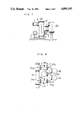
FIG. 5 is a sectional side view taken along the line V--V of FIG. 1;
FIG. 6 is an enlarged schematic cross-sectional view of an essential portion shown in FIG. 5;
FIG. 7 is a sectional side view of another embodiment of the structure shown in FIG. 5;
FIG. 8 is a schematic plan view of a gas-insulated switchgear equipment of another embodiment of the present invention;
FIG. 9 is a left side view of the gas-insulated switchgear equipment shown in FIG. 8; and
FIG. 10 is a connection diagram of the gas-insulated switchgear shown in FIG. 8.
DESCRIPTION OF THE PREFERRED EMBODIMENTS
Embodiments of the present invention will be described hereinafter with reference to the accompanying drawings. A circuit shown in FIG. 4 is called a one-and-a-half circuit breaker system to which gas-insulated switchgear equipment according to the present invention is applied. Three circuit breakers CB1, CB2 and CB3, having at their opposite sides disconnecting switches DS11 and DS12, DS21 and DS22, DS31 and DS32, are placed on a fixing base and electrically connected in series. Outside led-out means 5A and 5B such as cable heads are led out from points between the disconnecting switches. The three circuit breakers CB1, CB2, and CB3 connected in series are connected between main bus bars 1 and 7.
Gas-insulated switchgear equipment based on the circuit arrangement is shown in FIG. 1. The circuit breakers CB1, CB2, and CB3 are of a vertical type and include a breaking unit adapted for three or one phase disposed in a grounding tank which is filled with insulating gas. The circuit breakers CB1, CB2, and CB3 are disposed on a straight line. Led-out portions 11, 13, 14, and 15 of terminals and connecting bus bars 3, 4, which are used to electrically interconnect the circuit breakers as indicated by broken lines in FIG. 1, are provided at one side of the circuit breakers CB1, CB2, and CB3. In more detail, as shown in FIGS. 1 to 3, the circuit breaker CB1 has a led-out portion 11 provided at an upper portion thereof that leads out an upper terminal of the breaking unit to the one side, and the adjacent circuit breaker CB2 has a led-out portion 13 provided at an upper portion thereof and another led-out portion 14 provided at a lower portion thereof which lead upper and lower terminals of the breaking unit to the one side, respectively. A connecting bus bar 4 to interconnect the led-out portions 11, 13 is also disposed at the one side. The circuit breaker CB3 has, as shown in FIGS. 1 to 3, a led-out portion 15 at a lower portion thereof which leads a lower terminal of the breaking unit to the one side. A connecting bus bar 3 to interconnect the led-out portions 14, 15 is also disposed at the one side. A lower terminal of the breaking unit of the circuit breaker CB1 is led by a led-out portion 12 provided at a lower portion of the circuit breaker to the other side of the circuit breaker and is connected to a main bus bar 1 extending in a direction of the arrangement of the circuit breakers. Similarly, as can be understood from FIGS. 1 to 3, an upper terminal of the breaking unit of the circuit breaker CB3 is led by a led-out portion 16 extending from the other side of the circuit breaker and is connected to a main bus bar 7 which extends above and generally in parallel with the main bus bar 1. In the embodiment, as shown in FIG. 1, a disconnecting switch DS11 for the circuit breaker CB1 is provided within the main bus bar 1 and a disconnecting switch DS12 is provided within the connecting bus bar 4. A disconnecting switch DS21 for the circuit breaker CB2 is provided within the connecting bus bar 4, and a disconnecting switch DS22 is provided within the connecting bus bar 3. A disconnecting switch DS31 for the circuit breaker CB3 is provided within the connecting bus bar 3 and the disconnecting switch DS32 is provided within the main bus bar 7 extending at a higher level.
As shown in FIGS. 1 and 2, outside led-out devices 5A and 5B are connected to side portions of the connecting bus bars 3 and 4. Each of the outside led-out devices 5A and 5B that extends downward comprises a casing, a connecting conductor disposed in the casing, and an insulated terminal while establishing gas-insulation. That is, the outside led-out device 5A is connected to a side portion of the connecting bus bar 4 interconnecting the circuit breakers CB1 and CB2 and the outside led-out device 5B is connected to a side portion of the connecting bus bar 3 interconnecting the circuit breakers CB2 and CB3, and these devices are disposed such that they extend downward from their connecting portions.
Accordingly, the outside led-out device 5A is connected between the disconnecting switches DS12 and DS21 in the connecting bus bar 4. Similarly, the outside led-out device 5B is connected between the disconnecting switches DS22 and DS31 in the connecting bus bar 3.
The circuit arrangement shown in FIG. 4 will now be described. It should be noted here that the led-out portions 11, 13, 14, 15 and the connecting bus bars 3, 4 used to establish electrical connection between the circuit breakers CB1, CB2, CB3 are not placed on portions of the circuit breakers facing each other. With the construction, it is possible to reduce a distance between, for example, the circuit breakes CB1, CB2 to an extent of an axial length of the connecting bus bar 4 inclusive the disconnecting switches DS12, DS21.
In this embodiment, as three circuit breakers CB1, CB2, CB3 are arranged on the straight line and are electrically connected in series, two connecting bus bars 3, 4 are required. However, as the led-out portions 11, 13 respectively provided at the upper portion of the circuit breakers CB1, CB2 are interconnected by the connecting bus bar 3 and the led-out portions 14, 15 respectively provided at the lower portion of the circuit breakers CB2, CB3 are interconnected by the connecting bus bar 4, it is possible to vertically dispose the both connecting bus bars 3, 4 substantially parallel with each other with a linear structure, so that the structure thereof can be made simple. In this construction, the positions of connections between the circuit breakers and the outside led-out devices 5A and 5B and the heights of the devices are different from each other, and the connecting position of the outside led-out device 5B connected to the connecting bus bar 3 coincides with a level of the led-out portion 15 leading out the lower terminal of the circuit breaker CB3, as shown in FIGS. 2, 3, 5. In a case where the outside led-out device 5B is a cable head, the height does not become a disadvantage by structuring the cable head as illustrated in FIG. 6. That is, internal conductors 9, which are provided within the connecting bus bar 3 are led through a connecting portion l7a formed in a portion of cable head casing 17 and are turned upward along a side of cable heads 6 and are connected to upper terminals of the cable heads 6. Since conductors 8 turned upward face insulators of the cable heads 6, they can be disposed within the cable head casing 17 without increasing the diameter of the casing 17 while a suitable degree of insulation from the, cable head casing 17 is maintained. Therefore, when cable heads are used, it is possible for the outside led-out devices 5A, 5B to have identical appearances except for the positions of the portions connected to the connecting bus bars 3, 4.
In order to make the outside led-out device 5A connected to the connecting bus bar 4 and the outside led-out device 5B connected to the connecting bus bar 3 have the same height, an arrangement, for example as shown in FIG. 7, may be adapted in which an upwardly extending intermediate connecting bus bar 3a is connected at its lower end of the lower led-out portion 15 of the circuit breaker CB3 and is connected at its upper end to the outside led-out device 5B at the same level as the led-out portions of the circuit breakers CB1, CB2. With this construction, the outside led-out devices 5A, 5B have the same height, so that parts for the devices can be commonly used and a side profile of the gas-insulated switchgear equipment can be a suitable profile.
The connecting bus bars 3, 4 and the intermediate connecting bus bar 3a, which are used to connect the circuit breakers CB1, CB2, CB3 in series so as to construct a plurality of gas-insulated switchgear devices of the one-and-a-half circuit breaker type, may be of a type having a cylindrical casing in which a connection conductor in a gas-insulation manner is disposed similarly with the well known main bus bars 1, 7, or of other specifically designed types.
FIGS. 8 to 10 show gas-insulated switchgear equipment of another embodiment according to the present invention. This embodiment is based on a ring bus bar type of circuit arrangement shown in FIG. 10, in which the circuit breakers CB1, CB3 located at both ends of a series connection of three circuit breakers are connected to a main bus bar 20.
This embodiment will be described with reference to FIG. 8 and FIG. 9. In this embodiment, components identical to those of the first embodiment are indicated by the same reference characters and descriptions for the same constructions are omitted. This embodiment will be described with respect to points of difference from the first embodiment.
As can be understood from comparison between the circuit shown in FIG. 4 and the circuit shown in FIG. 10, the connection between the circuit breakers CB1 and CB2 and the connection between the circuit breakers CB2 and CB3 are the same as the circuit shown in FIG. 4 and only the connection between the circuit breakers CB1 and CB3 is different. That is, as shown in FIGS. 8 and 9, a led-out portion 12 which leads out a lower terminal of the circuit breaker CB1 in an opposite side to the connecting bus bar 4 side is connected to a portion of a main bus bar 20 which extends downward from the main bus bar 20 so that it is generally L-shaped, while a led-out portion 16 which leads out an upper terminal of the circuit breaker CB3 in an opposite side to the connecting bus bar 3 side is connected to the main bus bar 20 which extends at a higher level in a direction of an arrangement of the circuit breakers, thus constituting gas-insulated switchgear equipment corresponding to the ring bus bar system shown in FIG. 10. The main bus bar 20 may be disposed so as to extend at a lower level. In this construction also, the circuit breakers CB1, CB2 and CB3 are arranged on a straight line and the main bus bar 20 is disposed at one side of the arrangement of the circuit breakers and is extended in the direction of the arrangement, and the connecting bus bars 3, 4 and the outside led-out devices 5A, 5B are disposed on the other side as with the first embodiment. Therefore, the circuit breakers can be disposed closer to each other in the direction of the arrangement, so that total fixing space can be reduced.
As can be understood from the above-described embodiments, the present invention can be applied to a gas-insulated switchgear system, in which a plurality of gas-insulated switchgear devices are provided, in each of which a plurality of circuit breakers are arranged on a straight line. One or two main bus bars are provided, extending in the direction of the arrangement, and the circuit breakers and the main bus bar or bars are interconnected.
As described above, a plurality of vertical-type circuit breakers are closely arranged on a substantially straight line and connecting bus bars interconnecting the circuit breakers and outside led-out devices are provided on one side of the arrangement of the circuit breakers and one or more main bus bars are extended on the other side of the arrangement. Therefore, no connecting bus bars exist between opposite portions of the circuit breakers as in the case of the conventional system, so that a plurality of gas-insulated switchgear equipments can be closely disposed, thereby reducing the installation space. Also, electrical connection among the elements can be easily established.