US4890188A - Solenoid driver system - Google Patents
Solenoid driver system Download PDFInfo
- Publication number
- US4890188A US4890188A US07/252,980 US25298088A US4890188A US 4890188 A US4890188 A US 4890188A US 25298088 A US25298088 A US 25298088A US 4890188 A US4890188 A US 4890188A
- Authority
- US
- United States
- Prior art keywords
- solenoid
- high side
- optical isolator
- low side
- signal
- Prior art date
- Legal status (The legal status is an assumption and is not a legal conclusion. Google has not performed a legal analysis and makes no representation as to the accuracy of the status listed.)
- Expired - Lifetime
Links
- 230000003287 optical effect Effects 0.000 claims abstract description 31
- 239000003292 glue Substances 0.000 claims abstract description 20
- 238000011084 recovery Methods 0.000 claims abstract description 4
- 230000009977 dual effect Effects 0.000 claims description 7
- 230000000295 complement effect Effects 0.000 claims description 5
- 239000003990 capacitor Substances 0.000 description 22
- 238000010586 diagram Methods 0.000 description 9
- 239000002699 waste material Substances 0.000 description 2
- 239000000853 adhesive Substances 0.000 description 1
- 230000001070 adhesive effect Effects 0.000 description 1
- 230000003247 decreasing effect Effects 0.000 description 1
- 230000005669 field effect Effects 0.000 description 1
- 238000001914 filtration Methods 0.000 description 1
- 230000017525 heat dissipation Effects 0.000 description 1
- 238000000034 method Methods 0.000 description 1
- 238000012986 modification Methods 0.000 description 1
- 230000004048 modification Effects 0.000 description 1
- 230000003134 recirculating effect Effects 0.000 description 1
- 239000007787 solid Substances 0.000 description 1
- 230000001360 synchronised effect Effects 0.000 description 1
- 230000001960 triggered effect Effects 0.000 description 1
Images


Classifications
-
- H—ELECTRICITY
- H01—ELECTRIC ELEMENTS
- H01H—ELECTRIC SWITCHES; RELAYS; SELECTORS; EMERGENCY PROTECTIVE DEVICES
- H01H47/00—Circuit arrangements not adapted to a particular application of the relay and designed to obtain desired operating characteristics or to provide energising current
- H01H47/22—Circuit arrangements not adapted to a particular application of the relay and designed to obtain desired operating characteristics or to provide energising current for supplying energising current for relay coil
- H01H47/32—Energising current supplied by semiconductor device
- H01H47/325—Energising current supplied by semiconductor device by switching regulator
Definitions
- the present invention pertains to a solenoid driver system, and more specifically, a solenoid driver system for energizing a solenoid coil with a rapid rise output signal that energizes the solenoid coil for rapid turn on and reduces the time lag between a turn on signal and the actual energizing of the coil.
- the particular application for the present invention is for a glue gun applicator, requiring accurate turn on of the solenoid.
- the solenoid control would tend to burn out the solenoids or the turn on time was not accurate.
- the glue gun was left on all of the time, or in the alternative, a pulse was used to turn on a solid state relay that was synchronized to the AC line. Based on a 60-cycle AC line and the point of the cycle, the inaccuracy of previous dispensing methods of solenoid control could be as much as 8 milliseconds between high and low peaks, depending on where the control pulse was applied in reference to the AC line which is completely asynchronous. This resulted in sporadic glue dispensing and solenoid control.
- the present invention overcomes the disadvantages of the prior art by providing control of a solenoid with low power where the modulating circuit and the trigger circuit maintain the coil power to a reasonably low value, and there are no AC synchronization problems. This provides that the use of the solenoid coil becomes accurate and economical. When the present invention is applied to glue dispensing, accuracy is extremely enhanced in providing a consistent application of glue, and minimizing or eliminating waste of the glue.
- the general purpose of the present invention is to provide a solenoid driver system which converts a 120 volt AC power supply to a fully rectified output signal, consisting of an initial turn on or pulse of a relatively high current followed by a relatively low holding current which is pulsed width controlled.
- the solenoid driving system is for a glue applicator, and can be used in any other type of an applicator requiring the switching of a solenoid coil. Teachings of this disclosure are applicable for any input control signal, line voltage, and the solenoid coil voltage, current and power requirements.
- a solenoid driver system including a power supply providing a driving power supply voltage, a high side logic voltage and a low side logic voltage.
- a control pulse connects to a high side optical isolator and a low side optical isolator.
- a high side buffer connects between a solenoid driver stage and the high side optical isolator.
- a trigger circuit and delay circuit connect to a low side optical isolator and to a gate.
- a free-running gate also connects to the gate.
- the gate connects to shut down logic, which connects to the low side buffer, and which connects to the solenoid driver stage.
- a current sensing fault logic connects between the solenoid driver stage and the shut down logic.
- the solenoid driver stage outputs an initial turn on current pulse followed by a free-running current width of the holding current pulse, and frequency of the holding current pulse is predetermined as the width of the initial turn on pulse.
- a solenoid driver system which provides an initial turn on current pulse of 3 milliseconds duration of a high DC voltage to energize a solenoid coil and then provides a holding current pulse of 3 milliseconds every 35 milliseconds for the remainder of the signal duration, by way of example, for purposes of illustration only, and not to be construed as limiting of the present invention.
- This signal provides minimal power dissipation in the solenoid, providing for long life of the solenoid coil and minimal heat dissipation.
- Another significant aspect and feature of the present invention is a solenoid driver system which provides for accurate dispensing of glue from a glue applicator or glue gun.
- a further significant aspect and feature of the present invention is a solenoid driver system which is not asynchronous to the AC power line.
- the solenoid driver system provides that a solenoid can operate in a low power mode because the modulating circuit and the trigger circuit maintains the coil power at a low value. This provides a more accurate and economical dispensing of glue, providing a glue stitch pattern which is consistent in application and eliminating waste of glue.
- FIG. 1 illustrates a front perspective view of a solenoid driver system
- FIG. 2 illustrates a front view of the housing
- FIG. 3 illustrates an electrical circuit block diagram of the solenoid driver system
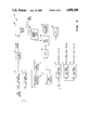
- FIGS. 4A illustrates the layout of the electrical schematic diagrams, of FIGS. 4B-4F;
- FIG. 4B-4F illustrate the electrical circuit of the solenoid driver system
- FIG. 5 illustrates a mode of operation discussion of the solenoid driver transistor bridge
- FIG. 6 illustrates a timing diagram for designated components.
- FIG. 1 illustrates a front perspective view of a solenoid driver system 10 including a housing 12 with a hinged door 14.
- a power switch 16 a signal switch 18, and a screw latch 20 position on the hinged door 14.
- a plurality of cable lock nuts including 110 volts AC, 24 volts DC control signal in, and solenoid driver signal out mount on the bottom of the housing 12.
- dual screw type lock downs can be utilized about the sides of the housing.
- FIG. 2 illustrates a front view of the housing 12 with the hinged door 14 open, and illustrates a circuit board 28 with the major components mounted thereon as later described in detail, and as illustrated mounted on the circuit board 28.
- FIG. 3 illustrates an electrical circuit block diagram 30 of the solenoid driver system 10.
- the AC input 22 is applied to connector J2 of FIG. 2, and is rectified by a rectifier bridge CR3. This is then filtered by a filter capacitor C1 of FIG. 4F which serves as the driving voltage for the solenoid through the driving power supply 32.
- Driving voltage is typically 160 to 170 volts DC.
- the AC input 22 also connects to a transformer T1 which has two separate primaries which generates two separate independent 12 volt DC supply voltages for a high side logic voltage 34 and a low side logic voltage 36.
- a control pulse 38 is inputted at the connector J4 to a high side optical isolator 40 and a low side optical isolator 46.
- the high side optical isolator 40 connects to a high side buffer 44 and then to a transistor Q2 of FIG. 4.
- the low side optical isolator 46 connects to a trigger circuit 48 which then connects to a delay circuit 50 and a gate 52.
- a free-running oscillator 54 also connects to the gate 52.
- the gate 52 connects to a shut down logic 55, low side buffer 56, and then to a transistor Q1 of FIG. 4.
- a current sensing fault logic 58 connects between the solenoid driver stage 60 and the shut down logic 55.
- the shut down logic 55 connects to a fault indicator 62.
- FIG. 4A illustrates the layout of the electric circuit schematic diagram of FIGS. 4B-4F.
- the drawing sheets 4B-4F of the schematic diagram are positioned with respect to each other, and the circuit lines connect, providing a complete electrical schematic circuit diagram for the solenoid driver system 10.
- FIG. 4B illustrates a power supply connector J2 which is connected to the high voltage side as illustrated in heavy lines to connector J1 and which is rectified by bridge rectifier CR3 for the primary driving voltage for the solenoid. J2 also connects to the transformer T1.
- the voltage through transformer T1 generates two independent supplies of 12 volts utilizing bridge rectifiers CR7 and CR8, voltage regulators VR1 and VR2, and the respective filter capacitors.
- the two power supplies for the high side logic power and low side logic power isolate and serve to drive the two N channel field effect transistors Q1 and Q2 which switch the solenoid driver voltage.
- Capacitors C3, C8, C10 and C11 are filtering capacitors.
- Capacitors C2, C12, C14, C15, C17, C21, C22, C23 and C24 are bypass/decoupling capacitors.
- FIG. 4C illustrates an incoming control pulse signal through the connector J4 which is optically coupled through optical isolators U1 and U3 of FIG. 4D.
- the optical isolators U1 and U3 then generate two different independent pulses that are electrically isolated from each other.
- the top high side signal couples through the optical isolator U1 to the high side buffer, is Schmitt triggered by U2E, and then drives a complementary emitter follower stage (CEFS) of Q5 and Q6 which drives the gate of transistor Q2 of FIG. 4F.
- CEFS complementary emitter follower stage
- Q2 is the N channel FET in the upper part of the bridge of FIG. 4F.
- the high side optical isolator 40 of FIG. 3 includes a current limiting resistor R10, a small signal diode CR9, an optical isolator U1, a bypass/decoupling capacitor C4, a bypass/decoupling capacitor C9, and a pull-up resistor R5.
- the high side buffer 44 of FIG. 3 includes gates U2E, U2C, LED CR10, pull-up resistor R8, current limiting resistor R9, Q5-Q6 of the CEFS, and a zener diode CR5.
- Q1 and Q2 are high voltage N channel FETs.
- Q5 is a PNP small signal transistor.
- Q6 is a NPN small signal transistor.
- FIG. 4D illustrates the other optically isolated low side signal coupled through the optical isolator U3 which then triggers Schmitt trigger U6F.
- U6F drives the gate of the lower N channel FET Q1 of FIG. 4F through gates U6F, U6C, U10A, U10C, U10B, U6A, and U6B and through the complementary emitter follower stage (CEFS) Q3 and Q4 which drives the gate of Q1 of FIG. 4F.
- CEFS complementary emitter follower stage
- the low side optical isolator 46 of FIG. 3 and of FIG. 4D includes gates U3, a bypass/decoupling capacitor C13, a filter capacitor C18, and a pull-up resistor R16.
- a trigger circuit 48 of FIG. 3 and of FIG. 4D includes a Schmitt trigger U6F, a dual monostable U4A, a timing capacitor C20, and timing resistors R11 and R13.
- a delay circuit 50 of FIG. 3 and of FIG. 4D includes a dual monostable U4B, a timing capacitor C19, and a timing resistor R21.
- a free-running oscillator 54 of FIG. 3 and of FIG. 4D includes multivibrator U7, a timing resistors R22 and R24, a timing capacitor C25, a bypass/decoupling capacitor C26, a dual monostable U8, a timing capacitor C27, and a timing resistor R23.
- FIG. 4E illustrates the gate 52 of FIG. 3 including Schmitt trigger U6C, and quad nor gates U10A, U10B, U10C and U10D.
- the low side buffer 56 of FIG. 3 includes U6D, LED CR12, pull-up resistor R18, Schmitt trigger U6E, current limiting resistor R20, and an external LED.
- the low side buffer 56 also includes in FIG. 4F current limiting resistor R4, CEFS, Q3 and Q4, a current limiting resistor R3, a zener diode CR4, and a filter capacitor C7.
- the current sensing fault logic 58 of FIG. 3 and of FIG. 4E includes comparator U5, voltage divider resistors R12, R14 and R15, small signal diode CR11, filter capacitor C16, pull-up resistor R17, current sensing resistor RI of FIG. 4F, current limiting resistor R7, filter capacitor C6, and zener diode CR6.
- the shut down logic 54 of FIG. 3 and of FIG. 4E includes dual flip-flop U9B, timing resistor R25, timing capacitor C28, pull-up resistor R19, LED CR13, and quad nor gate U10B.
- FIG. 4F illustrates the solenoid driver stage 60 of FIG. 3, and includes N channel FETs Q1 and Q2, fast recovery diodes CR1 and CR2, and the coil of the external solenoid.
- FIG. 4F also includes the sensing resistor R1 for the current sensing fault logic and components of a voltage suppressor MOV 1, a filter capacitor C1, and a bleeder resistor R2.
- the low side buffer includes a current limiting resistor R4, the CEFS Q3 and Q4, the current limiting resistor R3, the filter capacitor C7, and the zener diode CR4.
- the specific circuit carrying the solenoid driving power is illustrated in a heavy line designated SDP.
- a constant pulse input on the control signal J4 generates a pulse at U4.
- This pulse is typically 3 milliseconds by way of example and for purposes of illustration only, and is adjusted by selection of the capacitor C20 and the resistor R11.
- This is then gated by U10A, U10B, and U10C through the Schmitt trigger, and also drives the transistor Q1.
- the multi-vibrator U7 generates a pulse train about 3 milliseconds wide every 35 milliseconds, by way of example and for purposes of illustration only and not to be construed as limiting of the present invention.
- This is then gated by U10C and U10D to drive Q1.
- the monostable U4A When the pulse train is applied to J4, the monostable U4A generates an initial pulse.
- This signal out of U6F and then U6C gates the pulse train from U8A through U10A, U10D and U10C so that the solenoid coil is pulsed rather than driving a DC signal through the coil.
- the solenoid driver system drives a solenoid, such as a solenoid in a glue applicator or any like apparatus incorporating a solenoid, and which requires control of the solenoid in response to a signal voltage.
- the solenoid driver system generates a turn on signal that enables the solenoid, such as that of a glue gun applicator, to energize quickly because of a rapid rise solenoid signal.
- the solenoid driver stage of two switching transistors and two high voltage fast recovery diodes are connected to a control pulse through the high side optical isolator and the high side buffer, and the low side optical isolator and the low side buffer.
- the low side circuit includes a trigger circuit and a delay circuit connected to a gate along with a free-running oscillator for periodically energizing the low side drive of the circuit in a mode as long as the input signal is energized. This ensures that the amount of current dissipated in the solenoid coil is small.
- the current sensing fault logic and shut down logic are provided to prevent damage to the solenoid driver system circuitry or the solenoid coil.
- FIG. 5 illustrates a discussion of the modes of operation of the solenoid driver transistor bridge including the two transistors Q1 and Q2, the two rectifiers CR1 and CR2, and the external solenoid coil.
- mode A no current flows and both transistors are off.
- mode B maximum current flows when Q2 and Q1 are on.
- mode C a free-wheeling current or recirculating current flows through Q2 and CR1.
- mode D the solenoid is turned off rapidly by CR2 and CR1. Table 1 summarizes the four modes of operation.
- FIG. 6 illustrates the timing diagram for the components as designated on the vertical axis of the diagram over time on the horizontal axis. Reference is further directed to the solenoid coil to FIG. 5 which discloses the modes of operation for modes A, B, C and D with respect to time.
Landscapes
- Engineering & Computer Science (AREA)
- Power Engineering (AREA)
- Electronic Switches (AREA)
Abstract
Description
Claims (20)
Priority Applications (2)
| Application Number | Priority Date | Filing Date | Title |
|---|---|---|---|
| US07/252,980 US4890188A (en) | 1988-10-04 | 1988-10-04 | Solenoid driver system |
| JP1261227A JPH02162705A (en) | 1988-10-04 | 1989-10-04 | Solenoid driver |
Applications Claiming Priority (1)
| Application Number | Priority Date | Filing Date | Title |
|---|---|---|---|
| US07/252,980 US4890188A (en) | 1988-10-04 | 1988-10-04 | Solenoid driver system |
Publications (1)
| Publication Number | Publication Date |
|---|---|
| US4890188A true US4890188A (en) | 1989-12-26 |
Family
ID=22958345
Family Applications (1)
| Application Number | Title | Priority Date | Filing Date |
|---|---|---|---|
| US07/252,980 Expired - Lifetime US4890188A (en) | 1988-10-04 | 1988-10-04 | Solenoid driver system |
Country Status (2)
| Country | Link |
|---|---|
| US (1) | US4890188A (en) |
| JP (1) | JPH02162705A (en) |
Cited By (17)
| Publication number | Priority date | Publication date | Assignee | Title |
|---|---|---|---|---|
| WO1993007637A1 (en) * | 1991-10-11 | 1993-04-15 | Nova Corporation Of Alberta | Inductive load switch utilizing simplified gating |
| US5666286A (en) * | 1995-10-10 | 1997-09-09 | Nordson Corporation | Device and method for identifying a number of inductive loads in parallel |
| US5781398A (en) * | 1994-04-26 | 1998-07-14 | Honeywell Inc. | Dual fault tolerant actuator control system |
| US5812355A (en) * | 1995-09-25 | 1998-09-22 | Nordson Corporation | Electric gun driver |
| US5914849A (en) * | 1994-04-26 | 1999-06-22 | Kilovac Corporation | DC actuator control circuit with voltage compensation, current control and fast dropout period |
| US6061224A (en) * | 1998-11-12 | 2000-05-09 | Burr-Brown Corporation | PWM solenoid driver and method |
| US6850402B2 (en) | 2002-03-01 | 2005-02-01 | Honeywell International Inc. | Circuit and method for controlling current flow through a solenoid |
| US20050063204A1 (en) * | 2002-01-02 | 2005-03-24 | Andrew Westcott | Switching circuit and a method of operation thereof |
| US20050072949A1 (en) * | 2000-10-31 | 2005-04-07 | Nordson Corporation | PWM voltage clamp for driver circuit of an electric fluid dispensing gun and method |
| US20050077927A1 (en) * | 2002-01-02 | 2005-04-14 | Bae Systems Plc | Switching circuit and a method of operation thereof |
| US20050078496A1 (en) * | 2002-01-02 | 2005-04-14 | Westcott Andrew M G | Operation of a current controller |
| US20060126258A1 (en) * | 2004-12-10 | 2006-06-15 | Cuplin Richard P | Inductive load control |
| US7289878B1 (en) * | 2000-05-15 | 2007-10-30 | Nordson Corporation | Apparatus and method for modifying operation of an electric gun driver |
| US20080170348A1 (en) * | 2007-01-15 | 2008-07-17 | Yazaki North America, Inc. | Constant current relay driver with controlled sense resistor |
| US20100085676A1 (en) * | 2008-10-03 | 2010-04-08 | Honeywell International Inc. | Nested pulse width modulation control |
| US7740225B1 (en) * | 2000-10-31 | 2010-06-22 | Nordson Corporation | Self adjusting solenoid driver and method |
| DE102011001610A1 (en) | 2011-03-28 | 2012-10-04 | Faculty of Electrical Engineering University of Ljubljana | Method for actuating magnetic coil device, involves determining characterizing voltage ratio between current paths for magnetic coil current and between current paths for reference current based on sample values of measured voltage drops |
Citations (5)
| Publication number | Priority date | Publication date | Assignee | Title |
|---|---|---|---|---|
| US3864608A (en) * | 1973-05-21 | 1975-02-04 | Mkc Electronics Corp | Combination monostable and astable inductor driver |
| US4173030A (en) * | 1978-05-17 | 1979-10-30 | General Motors Corporation | Fuel injector driver circuit |
| US4438478A (en) * | 1981-08-10 | 1984-03-20 | Tokyo Shibaura Denki Kabushiki Kaisha | Power supplying apparatus |
| US4470095A (en) * | 1981-03-27 | 1984-09-04 | Siemens Aktiengesellschaft | Coil excitation arrangement for producing a pulse-shaped field of constant intensity |
| US4630165A (en) * | 1985-10-10 | 1986-12-16 | Honeywell Inc. | D.C. power control for D.C. solenoid actuators |
Family Cites Families (2)
| Publication number | Priority date | Publication date | Assignee | Title |
|---|---|---|---|---|
| JPS5936403B2 (en) * | 1978-04-04 | 1984-09-04 | 株式会社リコー | Drive circuit for electromagnetic coil in printer hammer drive magnet |
| JPS6193529A (en) * | 1984-10-15 | 1986-05-12 | 株式会社東芝 | Switch operating circuit |
-
1988
- 1988-10-04 US US07/252,980 patent/US4890188A/en not_active Expired - Lifetime
-
1989
- 1989-10-04 JP JP1261227A patent/JPH02162705A/en active Pending
Patent Citations (5)
| Publication number | Priority date | Publication date | Assignee | Title |
|---|---|---|---|---|
| US3864608A (en) * | 1973-05-21 | 1975-02-04 | Mkc Electronics Corp | Combination monostable and astable inductor driver |
| US4173030A (en) * | 1978-05-17 | 1979-10-30 | General Motors Corporation | Fuel injector driver circuit |
| US4470095A (en) * | 1981-03-27 | 1984-09-04 | Siemens Aktiengesellschaft | Coil excitation arrangement for producing a pulse-shaped field of constant intensity |
| US4438478A (en) * | 1981-08-10 | 1984-03-20 | Tokyo Shibaura Denki Kabushiki Kaisha | Power supplying apparatus |
| US4630165A (en) * | 1985-10-10 | 1986-12-16 | Honeywell Inc. | D.C. power control for D.C. solenoid actuators |
Cited By (25)
| Publication number | Priority date | Publication date | Assignee | Title |
|---|---|---|---|---|
| WO1993007637A1 (en) * | 1991-10-11 | 1993-04-15 | Nova Corporation Of Alberta | Inductive load switch utilizing simplified gating |
| US5914849A (en) * | 1994-04-26 | 1999-06-22 | Kilovac Corporation | DC actuator control circuit with voltage compensation, current control and fast dropout period |
| US5781398A (en) * | 1994-04-26 | 1998-07-14 | Honeywell Inc. | Dual fault tolerant actuator control system |
| US5812355A (en) * | 1995-09-25 | 1998-09-22 | Nordson Corporation | Electric gun driver |
| US5666286A (en) * | 1995-10-10 | 1997-09-09 | Nordson Corporation | Device and method for identifying a number of inductive loads in parallel |
| US6061224A (en) * | 1998-11-12 | 2000-05-09 | Burr-Brown Corporation | PWM solenoid driver and method |
| US7289878B1 (en) * | 2000-05-15 | 2007-10-30 | Nordson Corporation | Apparatus and method for modifying operation of an electric gun driver |
| US20050072949A1 (en) * | 2000-10-31 | 2005-04-07 | Nordson Corporation | PWM voltage clamp for driver circuit of an electric fluid dispensing gun and method |
| US6978978B2 (en) * | 2000-10-31 | 2005-12-27 | Nordson Corporation | PWM voltage clamp for driver circuit of an electric fluid dispensing gun and method |
| US7740225B1 (en) * | 2000-10-31 | 2010-06-22 | Nordson Corporation | Self adjusting solenoid driver and method |
| US7348689B2 (en) | 2002-01-02 | 2008-03-25 | Bae Systems Plc | Switching circuit and a method of operation thereof |
| US20050063204A1 (en) * | 2002-01-02 | 2005-03-24 | Andrew Westcott | Switching circuit and a method of operation thereof |
| US20050078496A1 (en) * | 2002-01-02 | 2005-04-14 | Westcott Andrew M G | Operation of a current controller |
| US20050077927A1 (en) * | 2002-01-02 | 2005-04-14 | Bae Systems Plc | Switching circuit and a method of operation thereof |
| US7187567B2 (en) | 2002-01-02 | 2007-03-06 | Bae Systems Plc | Operation of a current controller |
| US7692337B2 (en) | 2002-01-02 | 2010-04-06 | Bae Systems Plc | Switching circuit and a method of operation thereof |
| US6850402B2 (en) | 2002-03-01 | 2005-02-01 | Honeywell International Inc. | Circuit and method for controlling current flow through a solenoid |
| US7248453B2 (en) | 2002-03-01 | 2007-07-24 | Honeywell International, Inc. | Circuit and method for controlling current flow through a solenoid |
| US20060126258A1 (en) * | 2004-12-10 | 2006-06-15 | Cuplin Richard P | Inductive load control |
| US7405918B2 (en) | 2004-12-10 | 2008-07-29 | Yazaki North America, Inc. | Inductive load control |
| US7684168B2 (en) | 2007-01-15 | 2010-03-23 | Yazaki North America, Inc. | Constant current relay driver with controlled sense resistor |
| US20080170348A1 (en) * | 2007-01-15 | 2008-07-17 | Yazaki North America, Inc. | Constant current relay driver with controlled sense resistor |
| US20100085676A1 (en) * | 2008-10-03 | 2010-04-08 | Honeywell International Inc. | Nested pulse width modulation control |
| DE102011001610A1 (en) | 2011-03-28 | 2012-10-04 | Faculty of Electrical Engineering University of Ljubljana | Method for actuating magnetic coil device, involves determining characterizing voltage ratio between current paths for magnetic coil current and between current paths for reference current based on sample values of measured voltage drops |
| DE102011001610B4 (en) | 2011-03-28 | 2018-07-05 | Faculty of Electrical Engineering University of Ljubljana | Method for controlling magnetic coils (solenoids) |
Also Published As
| Publication number | Publication date |
|---|---|
| JPH02162705A (en) | 1990-06-22 |
Similar Documents
| Publication | Publication Date | Title |
|---|---|---|
| US4890188A (en) | Solenoid driver system | |
| FI892817A0 (en) | KOPPLINGSKRETS. | |
| ATE41571T1 (en) | SWITCHED DC VOLTAGE CONVERTER. | |
| JPS6293913A (en) | Dc control circuit for dc driven electromagnetic solenoid | |
| DE69315851D1 (en) | DRIVER CIRCUIT FOR LASER DIODES | |
| PT93364A (en) | COMUTATIVE MODULE POWER SUPPLY UNIT WITH FUNCTIONING OF PRONOUNCE MODE OF IMPULSE | |
| EP0322030A3 (en) | Arrangement for generating a sawtooth current | |
| DK0499138T3 (en) | Device for controlling a voltage pulse supply in an electrostatic filter | |
| JPS55117480A (en) | Protecting device for electric motor controlling switch | |
| JPH03233895A (en) | discharge lamp lighting device | |
| JPS61214982A (en) | Electric nailer | |
| JP2735346B2 (en) | Relay with control circuit to minimize arcing | |
| JPH0237594U (en) | ||
| SU1580445A1 (en) | Device for controlling dc electromagnet | |
| JPS6125087U (en) | switching regulator | |
| KR940003154A (en) | Power supply | |
| KR900005672A (en) | Flyback Switching Power Supply Unit | |
| KR890017969A (en) | SMPS type remote control TV driving circuit | |
| KR960030609A (en) | Telephone with flash display | |
| KR900010843Y1 (en) | High Voltage Stabilization Circuit Using PWM Integrated Device | |
| KR890009059A (en) | Regenerative circuit of PWM DC servo system | |
| ATE126391T1 (en) | POWER CIRCUIT FOR AN ELECTROMAGNET USING A DC SOURCE. | |
| SE9100183D0 (en) | DRIVE DEVICE FOR TRANSISTOR WITH ISOLATED CONTROL | |
| JPS6270456U (en) | ||
| JPH03115462U (en) |
Legal Events
| Date | Code | Title | Description |
|---|---|---|---|
| STCF | Information on status: patent grant |
Free format text: PATENTED CASE |
|
| AS | Assignment |
Owner name: LOCKWOOD TECHNICAL, INC., CALIFORNIA Free format text: ASSIGNMENT OF ASSIGNORS INTEREST.;ASSIGNORS:RUSSELL, GARY;KOZACKY, WALTER J.;REEL/FRAME:005175/0674;SIGNING DATES FROM 19880928 TO 19880930 |
|
| AS | Assignment |
Owner name: ILLINOIS TOOL WORKS INC. A CORP. OF DE., ILLINOI Free format text: ASSIGNMENT OF ASSIGNORS INTEREST.;ASSIGNOR:LOCKWOOD TECHNICAL, INC.;REEL/FRAME:006274/0447 Effective date: 19921009 |
|
| FEPP | Fee payment procedure |
Free format text: PAYOR NUMBER ASSIGNED (ORIGINAL EVENT CODE: ASPN); ENTITY STATUS OF PATENT OWNER: LARGE ENTITY |
|
| FEPP | Fee payment procedure |
Free format text: PAYER NUMBER DE-ASSIGNED (ORIGINAL EVENT CODE: RMPN); ENTITY STATUS OF PATENT OWNER: LARGE ENTITY Free format text: PAYOR NUMBER ASSIGNED (ORIGINAL EVENT CODE: ASPN); ENTITY STATUS OF PATENT OWNER: LARGE ENTITY |
|
| FPAY | Fee payment |
Year of fee payment: 4 |
|
| FEPP | Fee payment procedure |
Free format text: PAYER NUMBER DE-ASSIGNED (ORIGINAL EVENT CODE: RMPN); ENTITY STATUS OF PATENT OWNER: LARGE ENTITY Free format text: PAYOR NUMBER ASSIGNED (ORIGINAL EVENT CODE: ASPN); ENTITY STATUS OF PATENT OWNER: LARGE ENTITY |
|
| FPAY | Fee payment |
Year of fee payment: 8 |
|
| FPAY | Fee payment |
Year of fee payment: 12 |