US4889517A - Overlapping rasp bar rotor for axial flow combines - Google Patents
Overlapping rasp bar rotor for axial flow combines Download PDFInfo
- Publication number
- US4889517A US4889517A US07/348,344 US34834489A US4889517A US 4889517 A US4889517 A US 4889517A US 34834489 A US34834489 A US 34834489A US 4889517 A US4889517 A US 4889517A
- Authority
- US
- United States
- Prior art keywords
- rotor
- rasp
- rasp bar
- harvesting machine
- threshing
- Prior art date
- Legal status (The legal status is an assumption and is not a legal conclusion. Google has not performed a legal analysis and makes no representation as to the accuracy of the status listed.)
- Expired - Lifetime
Links
Images


Classifications
-
- A—HUMAN NECESSITIES
- A01—AGRICULTURE; FORESTRY; ANIMAL HUSBANDRY; HUNTING; TRAPPING; FISHING
- A01F—PROCESSING OF HARVESTED PRODUCE; HAY OR STRAW PRESSES; DEVICES FOR STORING AGRICULTURAL OR HORTICULTURAL PRODUCE
- A01F12/00—Parts or details of threshing apparatus
- A01F12/18—Threshing devices
- A01F12/22—Threshing cylinders with teeth
-
- A—HUMAN NECESSITIES
- A01—AGRICULTURE; FORESTRY; ANIMAL HUSBANDRY; HUNTING; TRAPPING; FISHING
- A01F—PROCESSING OF HARVESTED PRODUCE; HAY OR STRAW PRESSES; DEVICES FOR STORING AGRICULTURAL OR HORTICULTURAL PRODUCE
- A01F7/00—Threshing apparatus
- A01F7/02—Threshing apparatus with rotating tools
- A01F7/06—Threshing apparatus with rotating tools with axles in line with the feeding direction ; Axial threshing machines
Definitions
- This invention relates generally to axial flow harvesting machines, and more particularly, to an overlapping rasp bar rotor configuration for axial flow combines.
- an axial flow harvesting machine comprising at least one generally cylindrical rotor mounted within a casing and operable, in conjunction with the casing, to thresh and separate grain from straw material, and a plurality of threshing means provided around the periphery of the or each rotor and staggered axially thereof, characterised in that adjacent threshing means overlap axially of the associated rotor.
- adjacent threshing means are also arranged to overlap circumferentially of the associated rotor.
- the crop threshing means may be in the form of pairs of leading and trailing rasp bars with the trailing rasp bar of one pair overlapping axially and, where appropriate, circumferentially of the associated rotor, the leading rasp bar of the adjacent pair.
- FIG. 1 is a diagrammatic side view of the combine harvester
- FIG. 2 is a side view of one of two rotors of the combine harvester of FIG. 1 without any members for operating on the crop material shown mounted thereon;
- FIG. 3 is a perspective view of the rotor of FIG. 2 showing members for operating on the crop material mounted thereon;
- FIG. 4 is a section on the line IV--IV of FIG. 2;
- FIG. 5 is a partial cross-sectional view taken along the line V--V of FIG. 2, showing portions of the rotor as seen in end view in the direction of arrow F;
- FIG. 6 is a development of the rotor of FIG. 2 showing illustrative arrangements of different members for operating on crop material;
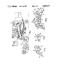
- FIG. 7 is a side view of mounting means for rasp bars
- FIG. 8 is a plan view of FIG. 7;
- FIG. 9 is a plan view of a leading rasp bar
- FIG. 10 is a section on the line X--X of FIG. 9;
- FIG. 11 is a plan view of a trailing rasp bar
- FIG. 12 is a section on line XII--XII of FIG. 11;
- FIG. 13 is a section through part of the rotor of FIG. 2; showing a leading rasp bar and a trailing rasp bar mounted on common mounting means;
- FIG. 14 is a cross sectional view of mounting means for a crop thinning element
- FIG. 15 is a plan view of the mounting means of FIG. 14;
- FIG. 16 is a side view of the mounting means of FIGS. 14 and 15 showing a crop thinning element mounted thereon;
- FIG. 17 is a perspective view of FIG. 16;
- FIG. 18 is a plan view of an alternative element for operating on crop material.
- FIG. 19 is a detail to a larger scale of FIG. 6.
- the combine harvester has a twin threshing and separating mechanism by way of right-hand and left-hand threshing and separating units each comprising a generally cylindrical rotor 1 mounted within a common, and generally correspondingly shaped, chamber 2.
- the inner surface of the chamber 2 is provided with helical fins in order to impart a helical and generally axial flow of crop material along the respective rotors 1 as is well known.
- Each rotor 1 is mounted for rotation on a forward and rearward stub shaft 3, of which only the forward stub shaft is shown in FIG. 3 of the drawings.
- the main body of each rotor 1 is a cylindrical tube 4 mounted on discs (not shown) supported on the respective stub shafts, and the forward end of each rotor is provided with an infeed section having a portion 5 of reduced diameter and a conical portion 6 which provides a transition between the portion 5 and the main body 4 of the rotor.
- a pair of auger flights 7 is provided at the infeed section 5, 6 of each rotor 1 which serves to transfer crop material from the top end of a crop conveyor 8 (FIG. 1) to the respective rotors 1.
- Each rotor 1 has a threshing section 9 immediately following the infeed section 5, 6, and the threshing section is followed by a separating section 11. It is conventional to provide rasp bars in the threshing section of a rotor and separating bars differing from the rasp bars.
- the present rotors 1 are no exception to this and in order to provide for the provision of rasp bars 12 and 13 (seen generally in FIG. 3 and in greater detail in FIGS. 9-13) rasp bar mounts 14 are provided at predetermined positions around the periphery of the threshing section of each rotor 1 in the threshing section.
- the rasp bar mounts 14 are provided in pairs and further mounts 15 are also provided around the periphery of the rotor in predetermined positions both in the threshing section and the separating section of each rotor 1.
- each rasp bar mount 14 is preformed and is an elongated rectangle as seen in plan view and comprises an arcuate base 16 conforming to the periphery of the rotor on which each mount is secured by welding or other means.
- An actual rasp bar mounting member 17 is provided on the base 16 and has two inclined surfaces 18 which are apertured at 19.
- Weld nuts 21 are provided in alignment with each aperture 19 on the underside of each mounting surface 18. It will be seen that the overall height of each rasp bar mount 14 is relatively small (and less than the overall height of the rasp bars 12 and 13) so that each mount has a very low profile such that it will not interfere with the smooth flow of crop material relative to the rotor in use of the combine harvester even if no rasp bar is mounted thereon. In this respect, the corners of the mounting members 17 and bases 16 are rounded so as not to present any sharp edge to the crop material.
- each pair may support a pair of rasp bars 12 and 13, the rasp bars 12 being leading rasp bars and the rasp bars 13 trailing rasp bars, with respect to the flow of crop material thereover which is indicated by arrow V in FIG. 19 with the direction of rotation of the rotor 1 being indicated by arrow R.
- the angle between the mounting surfaces 18 of each rasp bar mount 14 is 160° in the illustrated embodiment and is related to the diameter of the rotor used. Indeed, each inclined surface 18 is generally perpendicular to the corresponding radius of the rotor 1 drawn through the aperture 19 provided in said surface 18.
- the rasp bar mounts 14 of a given pair are welded or otherwise attached to each rotor main body 4 in an offset manner as seen in FIG. 2 of the drawings in order to incline the rasp bars 12 and 13 relative to the axis of each rotor 1 in order to assist in the helical movement of crop material around and along the rotor.
- each rasp bar 12 and 13 is relatively deep compared to known rasp bars so as to compensate for the low profile (height) of the rasp bar mounts 14 in order that there is the optimal radial clearance between the rasp bars and the inner surfaces of the respective chambers 2.
- This combination of rasp bar and rasp bar mounts gives rise to one important feature of the invention described and claimed in co-pending Patent Application No. 07/348,351, namely that the heads of bolts 22 securing the rasp bars 12 and 13 to the respective weld nuts 21 are located below (as seen in FIG. 13) the lowermost operative surfaces 23 of the rasp bars which are in fact the surfaces between conventional raised fins or rasps 24, 99 of the rasp bars.
- the heads of the bolts 22 are not contacted by crop material in operation of the combine harvester and are thus not subjected to abrasive wear which is the case with existing designs resulting, in many instances, in making it impossible to remove bolts by applying a spanner to the heads thereof in view of the severe wearing away of the latter.
- each is provided with a lead-in or ramp portion or ramp 25 which will be seen from FIG. 13 of the drawings to extend to the periphery of the associated rotor 1 along its entire forward edge in order to close the gap between the rasp bar and the rotor so that there is no likelihood of crop material becoming trapped therein and building up so as eventually to plug the rotor.
- the lead-in portion 25 of each leading rasp bar 12 is smooth and the fins or rasps 24 are provided along the upper edge of this lead-in portion.
- Each rasp bar 12 is provided with two apertures 26 to receive the securing bolts 22, these apertures being provided through portions of the finned area of the rasp bar.
- the fins 24 are extended forwardly at 24' in the area of the apertures 26 as best seen in FIGS. 9 and 19 of the drawings.
- each of the opposed and narrower sides or edges of the mounts 14 are provided with such an indentation or dimple 28 in order to avoid the need to ensure that a mount is the correct way round before attaching it to the rotor main body 4.
- the indentation 28 receiving one of the extensions 27 of a rasp bar 12 moreover provides an impact surface for more direct transfer of crop material impact forces on the lead-in portion 25 of the rasp bar 12 to the mounts 14. As such, less shearing forces are to be expected in the bolts 22 securing the rasp bars 12 to the mounts 14.
- trailing rasp bars 13 are of a different shape from the leading rasp bars 12, primarily because they do not require to have a lead-in portion and thus they comprise a basic rasp bar body provided with fins or rasps 29 and again, emphasis is laid on the fact that the rasp bars 13 are of a greater overall depth than conventional rasp bars in order that the heads of the bolts 22 can be located below the surfaces 23 in between the fins 29.
- the trailing rasp bar 13 of one pair of rasp bars 12, 13 is arranged to overlap, both axially and circumferentially of the rotor, the leading rasp bar 12 of an adjacent pair of rasp bars.
- the rear edge of each trailing rasp bar 13 is cut away at 30 in order to accommodate therebeneath the leading rasp bar 13 of an adjacent pair of rasp bars 12, 13 staggered axially of the associated rotor 1.
- This double overlapping of adjacent leading and trailing rasp bars 12, 13 ensures that there are no gaps which could otherwise trap crop material and cause hesitation of crop flow, possibly leading to eventual plugging of the rotor.
- Rasp bars have normally been a substantially regular rectangle, as seen in plan view, with the result that the front and rear edges thereof have been extending generally diametrally of the associated rotor 1 as shown in chain lines at 40 in FIG. 19.
- the present rasp bars 12 and 13 are of a more parallelogram form, as seen in plan view whereby the forward and rearward edges are inclined to a diametral plan of the rotor 1 so as to extend more concurrent with the direction of the flow V of crop material.
- the helical path of crop material over and across the rotor 1 is less disturbed by the front edge of the parallelogram type rasp bars 12, 13 than with the conventional substantially rectangular rasp bars used until now.
- the foregoing particularly can be observed at the transition area between the infeed section 5, 6 and the threshing section 9 of the rotor 1.
- FIG. 19 it can be seen that the free space between the auger flights 7 at the discharge end of the infeed section 5, 6 is almost fully closed off by the conventional rectangular rasp bars, obstructing a smooth takeover of crop material presented to the threshing section 9.
- the transition area is freed to some extent ensuring a smoother flow of crop material from the infeed section 5, 6 to the threshing section 9.
- FIG. 6 of the drawings the provision of permanent mounts 14 and 15 for crop operating elements enables the format of a given rotor to be modified in order to suit various crop types and crop conditions as further described in the co-pending Patent Application referred to above.
- the arrangement illustrated in FIG. 6 of the drawings is merely by way of giving examples of the different types of crop operating members which may be employed and does not necessarily illustrate one format of rotor which may be used.
- mounts 14 it will be seen that these may be fitted with rasp bars 12 and 13, as already described, although one or more leading or trailing rasp bars may be omitted if desired in order to reduce the threshing action which is usually desirable when harvesting beans, for example.
- one or more leading rasp bars 12 may be replaced by a crop operating element 31 (FIG. 18) which is a composite thinning element in the sense that it serves to cut or thin the mat of crop material prior to it being threshed in order that the threshing operation can be optimised.
- the thinning elements 31 comprise a base plate 32 on which a plurality of blades 33 are mounted which have a lead-in edge 34 and a generally V-shaped top edge 35. It will be appreciated that other types of thinning elements may be provided as required.
- the further mounts 15 also comprise an arcuate base 36 which, as with the base 16 of the mounts 14, conforms to the periphery of the associated tube 4 of the rotor 1.
- this base 36 of each further mount 15 is also an elongated rectangle and is provided with an actual mounting surface 37 for a crop operating member in the form of a thinning rod 38 which is threaded at one end in order to be received by a weld nut 39 provided on the underside of the mounting surface 37 in alignment with an aperture 41 therein.
- the thinning rods 38 need to be mounted both so as to trail with respect to the direction of rotation of the associated rotor 1 and also to point towards the rear end of the rotor.
- the mounting surface 37 is inclined in two planes and in the illustrated embodiment the inclination in one plane is such as to impart a trailing angle of 30° for each thinning rod 38, and an angle of 32° towards the rear end of the rotor.
- the thinning rod 38 is inclined rearwardly with an angle of 30° when seen in the direction of rotation and with respect to the radius of the rotor 1 passing through the bottom end of said thinning rod 38, as seen in FIG. 16.
- the angle of 32° is the angle between the longitudinal axis of the further mount 15 and the diametral plane of the rotor which that axis meets, as illustrated in FIG. 17. It should be appreciated that these angles of 30° and 32°, though of primary importance, are not critical.
- Each thinning rod 38 is provided with an hexagonal flange 42 immediately adjacent the threaded end portion in order that a spanner can be used to mount and dismount the rod in a mount 15.
- a socket spanner can be used which is particularly advantageous in cases where the separating concaves are not removable because it is possible to mount and dismount the thinning rods through the mesh of those concaves which is a distinct advantage. Otherwise, the rotor 1 and/or casing 2 has to be removed for servicing said thinning rods. In machines where the separator concaves are hingedly attached to the rotor casing 2, then there is no problem in this respect. It is normal to provide removable threshing concaves.
- FIGS. 2, 3 and 6 a number of further mounts 15 are disposed around the periphery of each rotor 1 and FIGS. 3 and 6 show the provision of thinning rods 38 on some of these mounts and not on others.
- the illustrated arrangement in this respect is merely by way of example but serves to show that a desired format of thinning rods can be used without any fear of the unused mounts 15 interfering in any way with the flow of crop material because, as with the mounts 14, the further mounts 15 have a low profile and rounded edges.
- the axial overlapping of adjacent threshing means, as opposed to axial staggering thereof, in accordance with the present invention has been found to help considerably in providing an optimum threshing configuration for smooth crop flow, low grain loss, minimum crop damage, and lower power consumption.
- the present invention results in less hesitation in crop flow, less crop "hits" (thus reducing hammering which can cause great operator discomfort) and a greater operating efficiency.
- the overlapping threshing means also provides a smoother transition between staggered mounting means with a reduced catching or trapping of crop material in the transition area.
Landscapes
- Life Sciences & Earth Sciences (AREA)
- Environmental Sciences (AREA)
- Threshing Machine Elements (AREA)
Abstract
Description
Claims (8)
Priority Applications (1)
| Application Number | Priority Date | Filing Date | Title |
|---|---|---|---|
| US07/348,344 US4889517A (en) | 1989-05-05 | 1989-05-05 | Overlapping rasp bar rotor for axial flow combines |
Applications Claiming Priority (1)
| Application Number | Priority Date | Filing Date | Title |
|---|---|---|---|
| US07/348,344 US4889517A (en) | 1989-05-05 | 1989-05-05 | Overlapping rasp bar rotor for axial flow combines |
Publications (1)
| Publication Number | Publication Date |
|---|---|
| US4889517A true US4889517A (en) | 1989-12-26 |
Family
ID=23367594
Family Applications (1)
| Application Number | Title | Priority Date | Filing Date |
|---|---|---|---|
| US07/348,344 Expired - Lifetime US4889517A (en) | 1989-05-05 | 1989-05-05 | Overlapping rasp bar rotor for axial flow combines |
Country Status (1)
| Country | Link |
|---|---|
| US (1) | US4889517A (en) |
Cited By (40)
| Publication number | Priority date | Publication date | Assignee | Title |
|---|---|---|---|---|
| US5035675A (en) * | 1985-07-24 | 1991-07-30 | J. I. Case Company | Convertible combine rotor |
| US5152717A (en) * | 1991-05-10 | 1992-10-06 | Deere & Company | Tooth mounting assembly for axial separator |
| US5192246A (en) * | 1991-11-15 | 1993-03-09 | Case Corporation | Rotor assembly for a combine |
| US5192245A (en) * | 1991-09-09 | 1993-03-09 | Case Corporation | Thresher elements for a combine |
| US5254036A (en) * | 1991-07-05 | 1993-10-19 | Great Plains Manufacturing, Incorporated | Sectional rasp bar assemblies for combine threshing cylinders |
| US5346429A (en) * | 1993-02-24 | 1994-09-13 | Case Corporation | Feeder assembly for a combine |
| EP0622014A1 (en) * | 1993-04-26 | 1994-11-02 | Deere & Company | Crop engaging element for axial flow separator |
| US5368522A (en) * | 1993-04-14 | 1994-11-29 | Case Corporation | Feeder-rotor assembly for combines |
| US5413531A (en) * | 1993-08-06 | 1995-05-09 | Case Corporation | Rotor assembly for a combine |
| US5919086A (en) * | 1997-09-25 | 1999-07-06 | Derry Farms, Inc. | Combine rotor and method |
| US6036598A (en) * | 1998-05-21 | 2000-03-14 | Deere & Company | Crop processing element for a rotary combine |
| WO2001037639A1 (en) | 1999-11-26 | 2001-05-31 | New Holland Belgium Nv | Discharge means for a trheshing and separating unit in a combine harvester |
| US6264553B1 (en) | 1999-08-16 | 2001-07-24 | Case Corporation | Rasp bar threshing element and assembly |
| US6325714B1 (en) | 1999-10-07 | 2001-12-04 | Case Corporation | Rotor assembly for a combine |
| US20050020330A1 (en) * | 2003-07-24 | 2005-01-27 | Deere & Company, A Delaware Corporation | Composite threshing element for a combine rotor |
| US20050026663A1 (en) * | 2003-07-29 | 2005-02-03 | Grywacheski Sheldon Joseph | Frusto-conical drum infeed and threshing region for a combine rotor |
| US20050043071A1 (en) * | 2003-08-12 | 2005-02-24 | Gribbin Stanley James | Rotor for a combine harvester |
| US20050096108A1 (en) * | 2003-11-05 | 2005-05-05 | Van Quekelberghe Eric P. | Axial flow combine harvester with adaptable threshing unit |
| EP1529436A1 (en) * | 2003-11-06 | 2005-05-11 | CNH Belgium N.V. | Axial flow combine harvester with adaptable separating unit |
| US7022013B1 (en) * | 2004-11-17 | 2006-04-04 | Cnh America Llc | Axial flow combine harvester with adaptable separating unit |
| US20070026913A1 (en) * | 2005-07-27 | 2007-02-01 | Kuchar George J | Crop processing element for a rotary combine |
| US20070049366A1 (en) * | 2005-08-26 | 2007-03-01 | Pope Glenn E | Threshing tine for a combine rotor |
| US20080167100A1 (en) * | 2007-01-05 | 2008-07-10 | Farley Herbert M | Locking system for attaching a threshing and/or separating element to a rotor of a threshing system |
| US20090042624A1 (en) * | 2007-08-07 | 2009-02-12 | Flickinger Wayne T | Combine Rotor Assembly With Progressive Pitch Element Pattern |
| US20090143123A1 (en) * | 2007-11-29 | 2009-06-04 | Glenn Pope | Adjustable Rear Rotor Discharge Flights |
| US20090197655A1 (en) * | 2008-02-01 | 2009-08-06 | Ellingson Michael B | Combine threshing components |
| US20110070933A1 (en) * | 2009-09-18 | 2011-03-24 | Jean Imbert | Threshing system including threshing elements having openings for grain passage |
| US20110207511A1 (en) * | 2010-02-24 | 2011-08-25 | Berthold Schwersmann | Mounting component for securing a crop handling element to a separator rotor |
| US8087982B1 (en) * | 2011-07-09 | 2012-01-03 | Kile Ronald J | Threshing bars and combine harvester thresher formed therewith |
| WO2012110347A1 (en) * | 2011-02-17 | 2012-08-23 | Laverda Spa | Crop engaging elements for a combine harvester separating rotor |
| US8529325B2 (en) | 2011-07-09 | 2013-09-10 | Ronald J. Kile | Threshing bars with cutting blades and combine harvester thresher formed therewith |
| JP2013183726A (en) * | 2012-03-12 | 2013-09-19 | Mitsubishi Agricultural Machinery Co Ltd | Threshing cylinder structure of thresher |
| US9807939B1 (en) * | 2015-10-06 | 2017-11-07 | Ronald J. Kile | Spiked threshing bar and combine harvester thresher formed therewith |
| EP3259979A1 (en) * | 2016-06-24 | 2017-12-27 | Taxil | Threshing element for combine harvester |
| US10342177B2 (en) * | 2015-02-25 | 2019-07-09 | Agco International Gmbh | Crop engaging element for a combine harvester separating rotor |
| US10368492B2 (en) * | 2015-10-07 | 2019-08-06 | Cnh Industrial America Llc | Rasp bar for a combine |
| US10440892B2 (en) | 2016-03-29 | 2019-10-15 | Cnh Industrial America Llc | Threshing and separating system with helical slats for an agricultural harvester |
| US11382273B2 (en) * | 2019-11-04 | 2022-07-12 | Cnh Industrial America Llc | Threshing components for combine harvester |
| US11464169B2 (en) * | 2017-12-28 | 2022-10-11 | Brian G. Robertson | Combine harvester concave threshing bar |
| US11641806B1 (en) * | 2020-10-07 | 2023-05-09 | Ronald J. Kile | Threshing bars and combine harvester thresher formed therewith |
Citations (5)
| Publication number | Priority date | Publication date | Assignee | Title |
|---|---|---|---|---|
| US4178943A (en) * | 1978-03-24 | 1979-12-18 | Deere & Company | Rotor for an axial flow rotary separator |
| US4362168A (en) * | 1981-01-30 | 1982-12-07 | Deere & Company | Separator for an axial flow rotary combine |
| US4422463A (en) * | 1978-03-24 | 1983-12-27 | Deere & Company | Rotor for an axial flow rotary separator |
| US4505279A (en) * | 1983-08-08 | 1985-03-19 | Sperry Corporation | Staggered spiral rasp bar segments for axial flow combines |
| EP0216060A1 (en) * | 1985-07-24 | 1987-04-01 | J. I. Case Company | Convertible combine rotor |
-
1989
- 1989-05-05 US US07/348,344 patent/US4889517A/en not_active Expired - Lifetime
Patent Citations (5)
| Publication number | Priority date | Publication date | Assignee | Title |
|---|---|---|---|---|
| US4178943A (en) * | 1978-03-24 | 1979-12-18 | Deere & Company | Rotor for an axial flow rotary separator |
| US4422463A (en) * | 1978-03-24 | 1983-12-27 | Deere & Company | Rotor for an axial flow rotary separator |
| US4362168A (en) * | 1981-01-30 | 1982-12-07 | Deere & Company | Separator for an axial flow rotary combine |
| US4505279A (en) * | 1983-08-08 | 1985-03-19 | Sperry Corporation | Staggered spiral rasp bar segments for axial flow combines |
| EP0216060A1 (en) * | 1985-07-24 | 1987-04-01 | J. I. Case Company | Convertible combine rotor |
Cited By (59)
| Publication number | Priority date | Publication date | Assignee | Title |
|---|---|---|---|---|
| US5035675A (en) * | 1985-07-24 | 1991-07-30 | J. I. Case Company | Convertible combine rotor |
| AU661234B2 (en) * | 1991-05-10 | 1995-07-13 | Deere & Company | Tooth mounting assembly for axial separator |
| US5152717A (en) * | 1991-05-10 | 1992-10-06 | Deere & Company | Tooth mounting assembly for axial separator |
| AU653018B2 (en) * | 1991-05-10 | 1994-09-15 | Deere & Company | Tooth mounting assembly for axial separator |
| US5254036A (en) * | 1991-07-05 | 1993-10-19 | Great Plains Manufacturing, Incorporated | Sectional rasp bar assemblies for combine threshing cylinders |
| US5192245A (en) * | 1991-09-09 | 1993-03-09 | Case Corporation | Thresher elements for a combine |
| US5192246A (en) * | 1991-11-15 | 1993-03-09 | Case Corporation | Rotor assembly for a combine |
| US5346429A (en) * | 1993-02-24 | 1994-09-13 | Case Corporation | Feeder assembly for a combine |
| US5368522A (en) * | 1993-04-14 | 1994-11-29 | Case Corporation | Feeder-rotor assembly for combines |
| EP0622014A1 (en) * | 1993-04-26 | 1994-11-02 | Deere & Company | Crop engaging element for axial flow separator |
| US5376047A (en) * | 1993-04-26 | 1994-12-27 | Deere & Company | Crop engaging element for an axial agricultural combine |
| US5413531A (en) * | 1993-08-06 | 1995-05-09 | Case Corporation | Rotor assembly for a combine |
| US5919086A (en) * | 1997-09-25 | 1999-07-06 | Derry Farms, Inc. | Combine rotor and method |
| US6036598A (en) * | 1998-05-21 | 2000-03-14 | Deere & Company | Crop processing element for a rotary combine |
| US6264553B1 (en) | 1999-08-16 | 2001-07-24 | Case Corporation | Rasp bar threshing element and assembly |
| US6325714B1 (en) | 1999-10-07 | 2001-12-04 | Case Corporation | Rotor assembly for a combine |
| WO2001037639A1 (en) | 1999-11-26 | 2001-05-31 | New Holland Belgium Nv | Discharge means for a trheshing and separating unit in a combine harvester |
| US6494782B1 (en) * | 1999-11-26 | 2002-12-17 | New Holland North America, Inc. | Threshing and separating unit of axial flow combines |
| US6500063B1 (en) * | 1999-11-26 | 2002-12-31 | New Holland North America, Inc. | Discharge means for a threshing and separating unit in a combine harvester |
| US20050020330A1 (en) * | 2003-07-24 | 2005-01-27 | Deere & Company, A Delaware Corporation | Composite threshing element for a combine rotor |
| US7059960B2 (en) * | 2003-07-24 | 2006-06-13 | Deere & Company | Composite threshing element for a combine rotor |
| US7070498B2 (en) | 2003-07-29 | 2006-07-04 | Deere & Company | Frusto-conical drum infeed and threshing region for a combine rotor |
| US20050026663A1 (en) * | 2003-07-29 | 2005-02-03 | Grywacheski Sheldon Joseph | Frusto-conical drum infeed and threshing region for a combine rotor |
| US6976912B2 (en) * | 2003-08-12 | 2005-12-20 | Stanley James Gribbin | Rotor for a combine harvester |
| US20050043071A1 (en) * | 2003-08-12 | 2005-02-24 | Gribbin Stanley James | Rotor for a combine harvester |
| US20050096108A1 (en) * | 2003-11-05 | 2005-05-05 | Van Quekelberghe Eric P. | Axial flow combine harvester with adaptable threshing unit |
| US20060025186A1 (en) * | 2003-11-05 | 2006-02-02 | Cnh American Llc | Axial flow combine harvester with adaptable threshing unit |
| GB2407749A (en) * | 2003-11-06 | 2005-05-11 | Cnh Belgium Nv | Axial flow combine harvester with adaptable threshing unit |
| EP1529436A1 (en) * | 2003-11-06 | 2005-05-11 | CNH Belgium N.V. | Axial flow combine harvester with adaptable separating unit |
| US7022013B1 (en) * | 2004-11-17 | 2006-04-04 | Cnh America Llc | Axial flow combine harvester with adaptable separating unit |
| US20070026913A1 (en) * | 2005-07-27 | 2007-02-01 | Kuchar George J | Crop processing element for a rotary combine |
| US20070049366A1 (en) * | 2005-08-26 | 2007-03-01 | Pope Glenn E | Threshing tine for a combine rotor |
| US20080167100A1 (en) * | 2007-01-05 | 2008-07-10 | Farley Herbert M | Locking system for attaching a threshing and/or separating element to a rotor of a threshing system |
| US7632182B2 (en) * | 2007-01-05 | 2009-12-15 | Cnh America Llc | Locking system for attaching a threshing and/or separating element to a rotor of a threshing system |
| US20090042624A1 (en) * | 2007-08-07 | 2009-02-12 | Flickinger Wayne T | Combine Rotor Assembly With Progressive Pitch Element Pattern |
| US7811162B2 (en) | 2007-08-07 | 2010-10-12 | Cnh America Llc | Combine rotor assembly with progressive pitch element pattern |
| US20090143123A1 (en) * | 2007-11-29 | 2009-06-04 | Glenn Pope | Adjustable Rear Rotor Discharge Flights |
| US7717777B2 (en) * | 2007-11-29 | 2010-05-18 | Deere & Company | Adjustable rear rotor discharge flights |
| US20090197655A1 (en) * | 2008-02-01 | 2009-08-06 | Ellingson Michael B | Combine threshing components |
| US20110070933A1 (en) * | 2009-09-18 | 2011-03-24 | Jean Imbert | Threshing system including threshing elements having openings for grain passage |
| US8142266B2 (en) * | 2009-09-18 | 2012-03-27 | Cnh America Llc | Threshing system including threshing elements having openings for grain passage |
| US20110207511A1 (en) * | 2010-02-24 | 2011-08-25 | Berthold Schwersmann | Mounting component for securing a crop handling element to a separator rotor |
| US8079899B2 (en) * | 2010-02-24 | 2011-12-20 | Claas Selbstfahrende Erntemaschinen Gmbh | Mounting component for securing a crop handling element to a separator rotor |
| WO2012110347A1 (en) * | 2011-02-17 | 2012-08-23 | Laverda Spa | Crop engaging elements for a combine harvester separating rotor |
| US9198358B2 (en) | 2011-02-17 | 2015-12-01 | Laverda Spa | Crop engaging elements for a combine harvester separating rotor |
| US8475247B1 (en) | 2011-07-09 | 2013-07-02 | Ronald J. Kile | Threshing bars and combine harvester thresher formed therewith |
| US8529325B2 (en) | 2011-07-09 | 2013-09-10 | Ronald J. Kile | Threshing bars with cutting blades and combine harvester thresher formed therewith |
| US8602856B2 (en) | 2011-07-09 | 2013-12-10 | Ronald J. Kile | Threshing bars and combine harvester thresher formed therewith |
| US8087982B1 (en) * | 2011-07-09 | 2012-01-03 | Kile Ronald J | Threshing bars and combine harvester thresher formed therewith |
| JP2013183726A (en) * | 2012-03-12 | 2013-09-19 | Mitsubishi Agricultural Machinery Co Ltd | Threshing cylinder structure of thresher |
| US10342177B2 (en) * | 2015-02-25 | 2019-07-09 | Agco International Gmbh | Crop engaging element for a combine harvester separating rotor |
| US9807939B1 (en) * | 2015-10-06 | 2017-11-07 | Ronald J. Kile | Spiked threshing bar and combine harvester thresher formed therewith |
| US10368492B2 (en) * | 2015-10-07 | 2019-08-06 | Cnh Industrial America Llc | Rasp bar for a combine |
| US10440892B2 (en) | 2016-03-29 | 2019-10-15 | Cnh Industrial America Llc | Threshing and separating system with helical slats for an agricultural harvester |
| FR3052957A1 (en) * | 2016-06-24 | 2017-12-29 | Taxil | TOWING ELEMENT FOR BREAD HARVESTERS |
| EP3259979A1 (en) * | 2016-06-24 | 2017-12-27 | Taxil | Threshing element for combine harvester |
| US11464169B2 (en) * | 2017-12-28 | 2022-10-11 | Brian G. Robertson | Combine harvester concave threshing bar |
| US11382273B2 (en) * | 2019-11-04 | 2022-07-12 | Cnh Industrial America Llc | Threshing components for combine harvester |
| US11641806B1 (en) * | 2020-10-07 | 2023-05-09 | Ronald J. Kile | Threshing bars and combine harvester thresher formed therewith |
Similar Documents
| Publication | Publication Date | Title |
|---|---|---|
| US4889517A (en) | Overlapping rasp bar rotor for axial flow combines | |
| US4946419A (en) | Axial flow harvesting machine | |
| US4936810A (en) | Crop thinning elements for axial flow combine | |
| EP1154682B1 (en) | Threshing and separating unit for axial flow combines | |
| US3946746A (en) | Harvesting machines | |
| US4004404A (en) | Rotary combine with improved concave | |
| US4362168A (en) | Separator for an axial flow rotary combine | |
| US7070498B2 (en) | Frusto-conical drum infeed and threshing region for a combine rotor | |
| US7749054B2 (en) | Modular separator element for a threshing system | |
| US4031901A (en) | Concave for an axial flow type combine | |
| US9456550B2 (en) | Threshing and separating device and combine harvester having the same | |
| US5376047A (en) | Crop engaging element for an axial agricultural combine | |
| US4192322A (en) | Axial flow separator with stepped threshing bar rotor | |
| US20220039322A1 (en) | Agricultural vehicle with adjustable rasp bars | |
| US3964492A (en) | Projections on rotor auger of axial flow combine | |
| US4159023A (en) | Infeed means for axial flow combine | |
| US4136704A (en) | Rotor for a combine | |
| US20090209307A1 (en) | Rear Rotor Cone | |
| EP0340875B1 (en) | Axial flow harvesting machine | |
| EP1529435A1 (en) | Axial flow combine harvester with adaptable threshing unit. | |
| CA1108501A (en) | Material flow retarders | |
| CA2373948A1 (en) | Flail straw chopper blade | |
| USRE31860E (en) | Harvesting machines | |
| US6976912B2 (en) | Rotor for a combine harvester | |
| CA1100841A (en) | Material flow retarders |
Legal Events
| Date | Code | Title | Description |
|---|---|---|---|
| AS | Assignment |
Owner name: FORD NEW HOLLAND INC., A CORP. OF DE, PENNSYLVANIA Free format text: ASSIGNMENT OF ASSIGNORS INTEREST.;ASSIGNORS:STRONG, RUSSELL W.;VAN QUEKELBERGHE, ERIC P. J.;REEL/FRAME:005071/0586 Effective date: 19890420 |
|
| STCF | Information on status: patent grant |
Free format text: PATENTED CASE |
|
| FEPP | Fee payment procedure |
Free format text: PAYOR NUMBER ASSIGNED (ORIGINAL EVENT CODE: ASPN); ENTITY STATUS OF PATENT OWNER: LARGE ENTITY |
|
| FPAY | Fee payment |
Year of fee payment: 4 |
|
| AS | Assignment |
Owner name: BLUE LEAF I.P., INC., DELAWARE Free format text: ASSIGNMENT OF ASSIGNORS INTEREST;ASSIGNOR:FORD NEW HOLLAND, INC.;REEL/FRAME:007388/0102 Effective date: 19941215 |
|
| FEPP | Fee payment procedure |
Free format text: PAYER NUMBER DE-ASSIGNED (ORIGINAL EVENT CODE: RMPN); ENTITY STATUS OF PATENT OWNER: LARGE ENTITY Free format text: PAYOR NUMBER ASSIGNED (ORIGINAL EVENT CODE: ASPN); ENTITY STATUS OF PATENT OWNER: LARGE ENTITY |
|
| FPAY | Fee payment |
Year of fee payment: 8 |
|
| FPAY | Fee payment |
Year of fee payment: 12 |