US488564A - Coal loader and distributer for box-cars - Google Patents
Coal loader and distributer for box-cars Download PDFInfo
- Publication number
- US488564A US488564A US488564DA US488564A US 488564 A US488564 A US 488564A US 488564D A US488564D A US 488564DA US 488564 A US488564 A US 488564A
- Authority
- US
- United States
- Prior art keywords
- platform
- shaft
- guide
- loader
- car
- Prior art date
- Legal status (The legal status is an assumption and is not a legal conclusion. Google has not performed a legal analysis and makes no representation as to the accuracy of the status listed.)
- Expired - Lifetime
Links
- 239000003245 coal Substances 0.000 title description 8
- 238000010276 construction Methods 0.000 description 3
- 241001137251 Corvidae Species 0.000 description 1
- 230000000994 depressogenic effect Effects 0.000 description 1
- 210000003746 feather Anatomy 0.000 description 1
- 238000009408 flooring Methods 0.000 description 1
- 229910052500 inorganic mineral Inorganic materials 0.000 description 1
- 239000002184 metal Substances 0.000 description 1
- 239000011707 mineral Substances 0.000 description 1
- 230000002093 peripheral effect Effects 0.000 description 1
Images

Classifications
-
- B—PERFORMING OPERATIONS; TRANSPORTING
- B65—CONVEYING; PACKING; STORING; HANDLING THIN OR FILAMENTARY MATERIAL
- B65G—TRANSPORT OR STORAGE DEVICES, e.g. CONVEYORS FOR LOADING OR TIPPING, SHOP CONVEYOR SYSTEMS OR PNEUMATIC TUBE CONVEYORS
- B65G21/00—Supporting or protective framework or housings for endless load-carriers or traction elements of belt or chain conveyors
- B65G21/10—Supporting or protective framework or housings for endless load-carriers or traction elements of belt or chain conveyors movable, or having interchangeable or relatively movable parts; Devices for moving framework or parts thereof
- B65G21/14—Supporting or protective framework or housings for endless load-carriers or traction elements of belt or chain conveyors movable, or having interchangeable or relatively movable parts; Devices for moving framework or parts thereof to allow adjustment of length or configuration of load-carrier or traction element
-
- Y—GENERAL TAGGING OF NEW TECHNOLOGICAL DEVELOPMENTS; GENERAL TAGGING OF CROSS-SECTIONAL TECHNOLOGIES SPANNING OVER SEVERAL SECTIONS OF THE IPC; TECHNICAL SUBJECTS COVERED BY FORMER USPC CROSS-REFERENCE ART COLLECTIONS [XRACs] AND DIGESTS
- Y10—TECHNICAL SUBJECTS COVERED BY FORMER USPC
- Y10S—TECHNICAL SUBJECTS COVERED BY FORMER USPC CROSS-REFERENCE ART COLLECTIONS [XRACs] AND DIGESTS
- Y10S198/00—Conveyors: power-driven
- Y10S198/95—Conveyor transverses wall aperture
Definitions
- FIGJ. 1 A first figure.
- My invention relates to a coal loader and distributer designed for use in connection with box-cars.
- the object of my invention is to provide a loader which will receive and convey the coal to opposite ends of the car, and deposit it compactly, without breakage.
- a further object of my invention is to provide a loader which is easily operated and may be readily introduced into a car.
- a further object of my invention is to provide means whereby when the loading of a car is commenced the conveyer may be held close to the floor thereof, and gradually elevated as the operation of loading proceeds.
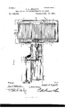
- Figure 1 is a plan view of the loader, in its operative position, with the endless platform or apron in the operative position within a box-car, the latter being partly broken away to show the loader:
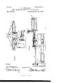
- Fig. 2 is an end view:
- Fig. 3 is a side view:
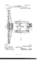
- Fig. 4 is a sectional view taken parallel with and through the main tilting shaft:
- Fig. 5 is a View of the lifting mechanism, showing the lever and gearing thereof:
- Fig. 6 is a longitudinal sectional view of the platform:
- Fig. 7 is a sectional view showing the platform folded, as seen while in troducing the loader into and withdrawing it from the car.
- the main tilting shaft of my improved loader is carried by a truck, A, runningupon track-rails, a a, and operated, to carry the platform into and withdraw it from a car, by means of a Windlass, B,- and cable, B, running around guide pulleys, b b, and connected to the truck.
- the truck carries an elevator, comprising the outer shell, 0, theinner shell, 0, fitting snugly in the outer shell and lifting mechanism to raise said inner shell.
- This lifting mechanism comprises the horizontal rock-shafts, D D, carrying cams, D D, which are adapted, when the shafts are turned, to engage rounded shoulders, d d, upon the inner shell (said rock-shafts and cams being mounted in the outer shell).
- the rock-shafts are provided, furthermore, upon corresponding extremities, with pinions, E E, both of which are engaged, simultaneously, by a common gear, E, which is, in turn, engaged by an arc-gear upon the extremity of an operating lever, F.
- the tilting-shaft, G is hollow andis mount ed in bearings, g g, upon the elevator, above described, said shaft carrying at. one end a guide-frame, H, supporting the distributing platform, K.
- This platform is provided with parallel side-bars, L L, which fit and slide in guide-grooves, It, in the inner surfaces of the vertical guide-plates, K K, at opposite ends of the guide-frame.
- the guideplates are connected, flush with the lower sides of said guide-grooves, with horizon tal guide-bars, Zr, 70'.
- the side-bars, above described are double, as shown in the plan View, Fig. 1, the outer members, Z Z, and inner members, Z Z, thereof, being parallel throughout.
- the platform is adapted to fold to enable it to be introduced through the door of a car, and for this purpose is formed in three sections, designated by the reference letters, P, P, and P, respectively.
- the sectional construction of the platform is attained by forming the sidebars thereof in sections, designated by the numerals 11, 12, and 13, respectively.
- each side-bar (and as a matter of course each member of each side bar) is formed of a series of three pivotally connected sections or parts, whereby the platform as an entirety is composed of an intermediate and two terminal sections, designated by referenee letters P, P and P, the sections or parts of the side ba s being indicated by the numerals 11, 12 and 13, respectively.
- I provide a winch, Q, mounted in a vertical guard-plate, K, and carrying a drum, Q, having parallel peripheral grooves, q q, in which are received and reeled the inner ends of the cables, q q, the outer ends of said cables being attached to the extremities of the adjacent side-bar of the platform.
- the vertical guard-plate When the loader is in its operative position, with the platform within the car, the vertical guard-plate fills the opening in the side of the car, approximately, and prevents the coal from being thrown out at that point.
- the parallel side-bars of the platform are held at their proper distance and in their proper relative positions by cross-bars, r r,
- crossbars have an additional function, also, in that they form the stays for the sheet metal flooring, R, which is formed in sections to correspond. with those of the platform-proper, the terminal sections thereof being hinged to the intermediate cross-bars, r r.
- the tilting-shaft G is tubular, and within it is mounted the conveyer-shaft, S, which carries, at one end, a sprocket-wheel, or pinion, s,to engage the conveyer-chain at the remote side of the platform and at an intermediate point a similar sprocket-wheel, or pinion, s, to engage the conveyer-chain at the near side of the platform, whereby as said shaft is rotated the oonveyer, or apron, is carried around the platform.
- the conveyer-shaft is also provided, at the opposite end, With a spur-wheel, T, which is connected, by means of a chain, T, with a similar spur-wheel, T, carried by the driving shaft, U.
- This driving shaft may be operated by any suitable power, as steam, and is provided with a spline, Lain which fits and operates a corresponding feather u upon the spur-wheel, the latter being held in alignment with the spur-wheel, T, and moved simultaneouslywith the truck by means of parallel arms,U U, projecting from the shell'of the truck and provided with eyes, u u, to embrace the driving-shaft.
- a spline Lain which fits and operates a corresponding feather u upon the spur-wheel, the latter being held in alignment with the spur-wheel, T, and moved simultaneouslywith the truck by means of parallel arms,U U, projecting from the shell'of the truck and provided with eyes, u u, to embrace the driving-shaft.
- V indicates a vertical worm-shaft, arranged upon the platform, adjacent to the hollow ti1ting-shaft, and provided with a-hand-wheehv, the tilting-shaft being provided with a Wormgear to be engaged by the worm to enable the platform to be tilted in either direction at the will of the operator.
- One of the side-bars of the platform is provided with a rack, W, engaged by a pinion, W, which is carried by a short shaft mounted upon the guide-frame.
- This gear although preferably operated from the drivingshaft, in any ordinary or well known manner,1s shown in the drawings provided with a hand-wheel, W, for convenience.
- the con veyer or apron is now operated continuously as the coal, or other mineral, is deposited thereon thus carrying the latter to the extreme end of the car and placing it quietly, without breaking.
- the platform is moved, by means of the rack and pinion to the other end, the engine by which the driving shaft is operated being reversed to cause the conveyer, or apron, to travel in the opposite direction.
- the bottom of the car has been sufficiently filled the platform is elevated by means of the lifting mechanism above described.
- the platform may be folded by the operation of the winch and withdrawn by means of the cable, the fact that the terminal sections of the platform fold upwardly enabling this to be accomplished readily and expeditiously.
- the hollow shaft carrying a guide-frame, the platform mounted in the guide-frame, the endless conveyer carried by the platform, and the conveyer shaft mounted in the hollow-shaft and provided at one end with a gear to engage the conveyer and at the other end with a gear which is connected to the said sprocket or chain gear, the hollow shaft being mounted upon a truck, all substantially as specified.
- a tilting-platform having an intermediate and terminal sections pivotally connected, and means to fold the terminal sections perpendicular to the intermediate section, substantially as specified.
Landscapes
- Engineering & Computer Science (AREA)
- Mechanical Engineering (AREA)
- Intermediate Stations On Conveyors (AREA)
Description
No Model.) 4 Sheets-Sheet 1 J. A; INGALLS'. GOAL LOADER AND DISTRIBUTER FOR BOX CARS.
No. 488,564. Patented Dec. 27, 1892.-
FIGJ.
4 Sheets-Sheet 2.
(N6 Model.)
' Patented Dec. 27 1892.
R 2 A v b i! 1 1 h w! ll ,5 b M H. a U F m H m o n m fi .5 m. M w w 73 R up E m 3 H L .H Lfi b o dd E Q i w 0 P Q t H O (No Model.) 4Sheets-Sheet 4.
' 'J. A INGALLSi COAL LOADER AN-DDISTRIBUTBR FOR BOX CARS. No. 488,564. Patented'Deo; 27, L892.
llllllllllllllllllllllllllllllll J w M1 alla 13 7716 eAfim jayS, 7a.?
m2 mums PETERS co. woman-no wasumu'ron, o.
UNITED STATES PATENT OFFICE.
JOSEPH A. INGALLS, OF EVANSTON, \VYOMING.
COAL LOADER AND DISTRIBUTER FOR BOX-CARS.
SPECIFICATION forming part of Letters Patent No. 488,564, dated December 27, 1892.
Application filed July 6 1892. Serial No. 439.149. (No model.)
To aZZ whom it may concern:
Be it known that I, JOSEPH A. INGALLS, a citizen of the United States, residing at Evanston, in the county of Uinta and State of Wyoming, have invented a new and useful Coal Loader and Distributer for Box-Oars, of which the following is a specification.
My invention relates to a coal loader and distributer designed for use in connection with box-cars.
The object of my invention is to provide a loader which will receive and convey the coal to opposite ends of the car, and deposit it compactly, without breakage.
A further object of my invention is to provide a loader which is easily operated and may be readily introduced into a car.
A further object of my invention is to provide means whereby when the loading of a car is commenced the conveyer may be held close to the floor thereof, and gradually elevated as the operation of loading proceeds.
Further objects of my invention will appear in the following description of my improved loader, given in connection with the drawings, wherein:
Figure 1 is a plan view of the loader, in its operative position, with the endless platform or apron in the operative position within a box-car, the latter being partly broken away to show the loader: Fig. 2 is an end view: Fig. 3 is a side view: Fig. 4is a sectional view taken parallel with and through the main tilting shaft: Fig. 5 is a View of the lifting mechanism, showing the lever and gearing thereof: Fig. 6 is a longitudinal sectional view of the platform: Fig. 7 is a sectional view showing the platform folded, as seen while in troducing the loader into and withdrawing it from the car.
The main tilting shaft of my improved loader is carried by a truck, A, runningupon track-rails, a a, and operated, to carry the platform into and withdraw it from a car, by means of a Windlass, B,- and cable, B, running around guide pulleys, b b, and connected to the truck. The truck carries an elevator, comprising the outer shell, 0, theinner shell, 0, fitting snugly in the outer shell and lifting mechanism to raise said inner shell. This lifting mechanism comprises the horizontal rock-shafts, D D, carrying cams, D D, which are adapted, when the shafts are turned, to engage rounded shoulders, d d, upon the inner shell (said rock-shafts and cams being mounted in the outer shell). The rock-shafts are provided, furthermore, upon corresponding extremities, with pinions, E E, both of which are engaged, simultaneously, by a common gear, E, which is, in turn, engaged by an arc-gear upon the extremity of an operating lever, F.
The tilting-shaft, G, is hollow andis mount ed in bearings, g g, upon the elevator, above described, said shaft carrying at. one end a guide-frame, H, supporting the distributing platform, K. This platform is provided with parallel side-bars, L L, which fit and slide in guide-grooves, It, in the inner surfaces of the vertical guide-plates, K K, at opposite ends of the guide-frame. The guideplates are connected, flush with the lower sides of said guide-grooves, with horizon tal guide-bars, Zr, 70'. The side-bars, above described are double, as shown in the plan View, Fig. 1, the outer members, Z Z, and inner members, Z Z, thereof, being parallel throughout. Between the extremities of the parallel members of the side-bars are mounted guide-rolls, M M, around which run the endless carrier-chains,N N, to which are attached the cross-bars, N N, of the platform, the endless chains and cross-bars comprising an endless apron or conveyer, O. The platform is adapted to fold to enable it to be introduced through the door of a car, and for this purpose is formed in three sections, designated by the reference letters, P, P, and P, respectively. The sectional construction of the platform is attained by forming the sidebars thereof in sections, designated by the numerals 11, 12, and 13, respectively. When the intermediate section of the platform is arranged in the guide-frame, the terminal sections may be folded up, vertically, as indicated in Fig. 7, so that the entire platform occupies a space smaller than the openingin the side of the car.
It will be noted that in the above description of the construction of the platform I have set forth that the platform is provided with parallel side bars, each comprising two parallel members, which I have designated collectively as well as individually by reference letters, and furthermore, it will be seen that each side-bar (and as a matter of course each member of each side bar) is formed of a series of three pivotally connected sections or parts, whereby the platform as an entirety is composed of an intermediate and two terminal sections, designated by referenee letters P, P and P, the sections or parts of the side ba s being indicated by the numerals 11, 12 and 13, respectively.
To accomplish the folding of the platform, as described, I provide a winch, Q, mounted in a vertical guard-plate, K, and carrying a drum, Q, having parallel peripheral grooves, q q, in which are received and reeled the inner ends of the cables, q q, the outer ends of said cables being attached to the extremities of the adjacent side-bar of the platform.
When the loader is in its operative position, with the platform within the car, the vertical guard-plate fills the opening in the side of the car, approximately, and prevents the coal from being thrown out at that point. The parallel side-bars of the platform are held at their proper distance and in their proper relative positions by cross-bars, r r,
- between the extremities of the side bars and similar cross-bars, r 1', between intermediate points of the side bars, the terminal crossbars, 4 r, forming the pivots for the guiderolls, M M, and the intermediate cross-bars, r r forming the pivots by which the inner ends of the terminal sections of the side-bars are connected to the adjoining ends of the intermediate sections thereof. These crossbars have an additional function, also, in that they form the stays for the sheet metal flooring, R, which is formed in sections to correspond. with those of the platform-proper, the terminal sections thereof being hinged to the intermediate cross-bars, r r.
The tilting-shaft G is tubular, and within it is mounted the conveyer-shaft, S, which carries, at one end, a sprocket-wheel, or pinion, s,to engage the conveyer-chain at the remote side of the platform and at an intermediate point a similar sprocket-wheel, or pinion, s, to engage the conveyer-chain at the near side of the platform, whereby as said shaft is rotated the oonveyer, or apron, is carried around the platform. The conveyer-shaft is also provided, at the opposite end, With a spur-wheel, T, which is connected, by means of a chain, T, with a similar spur-wheel, T, carried by the driving shaft, U. This driving shaft may be operated by any suitable power, as steam, and is provided with a spline, Lain which fits and operates a corresponding feather u upon the spur-wheel, the latter being held in alignment with the spur-wheel, T, and moved simultaneouslywith the truck by means of parallel arms,U U, projecting from the shell'of the truck and provided with eyes, u u, to embrace the driving-shaft.
V indicates a vertical worm-shaft, arranged upon the platform, adjacent to the hollow ti1ting-shaft, and provided with a-hand-wheehv, the tilting-shaft being provided with a Wormgear to be engaged by the worm to enable the platform to be tilted in either direction at the will of the operator.
One of the side-bars of the platform is provided with a rack, W, engaged by a pinion, W, which is carried by a short shaft mounted upon the guide-frame. This gear, although preferably operated from the drivingshaft, in any ordinary or well known manner,1s shown in the drawings provided with a hand-wheel, W, for convenience.
'Having now described, in detail, the construction of my coal loader and distributer, the operation thereof is as follows: The platform being in the folded position shown in Fig. 7, it is advanced and introduced through-the door of the car by operating the traction cable by means of the Windlass, the elevator being meanwhile depressed so that the bottom of the guide-frame is close to the floor of the car. After being properly introduced the platform is extended by operating the winch, thereby dropping the extremities or terminal sections of the platform to the plane of the intermediate section. The platform is now moved by means of the rack and pinion, above described, until one end is close to the end of the car, when the loader is in position for operation. The con veyer or apron is now operated continuously as the coal, or other mineral, is deposited thereon thus carrying the latter to the extreme end of the car and placing it quietly, without breaking. When one end of the car is sufficiently filled the platform is moved, by means of the rack and pinion to the other end, the engine by which the driving shaft is operated being reversed to cause the conveyer, or apron, to travel in the opposite direction. \Vhen the bottom of the car has been sufficiently filled the platform is elevated by means of the lifting mechanism above described.
If, during the operation of the loader, it is desirable to bring one end of the platform closer to the floor or closer to the roof of the car, this may be accomplished by tilting the platform by means of the tilting-mechanism consisting of the worm and gear, above described.
After both ends of the car have been sufficiently filled the platform may be folded by the operation of the winch and withdrawn by means of the cable, the fact that the terminal sections of the platform fold upwardly enabling this to be accomplished readily and expeditiously.
Having thus described my invention, what I claim and desire to secure by Letters Patent of the United States, is:
1. In a machine of the class described, the combination with a tilting shaft carried bya truck, of a platform supported upon said shaft, substantially as specified.
, 2. In a machine of the class described, the combination with a tilting shaft carried bya truck, of a platform supported upon said shaft, and comprising pivotally connected foldable sections, substantially as specified.
3. In a machine of the class described, the combination with a tilting shaft carried by a truck, of a platform mounted to slide in a frame upon said shaft, and means whereby the same may be moved longitudinally, substantially as specified.
4c. In a machine of the class described, the combination with a tilting shaft carried by a truck, of a platform supported upon said shaft and composed of pivotally-connected, foldable sections, a continuous conveyer or apron carried by rolls at the extremities of the terminal sections and means to operate said conveyer or apron, substantially as specified.
5. In a machine of the class described, the combination with a tilting orrock-shaft supported by a truck, and carrying a guide frame, of a sectional platform mounted to slide in said guide frame, and means to move the platform, substantially as specified.
6. The combination with a tilting shaft carried by a truck, of a platform supported upon said shaft, a stationary plate attached to the platform, an endless conveyeror apron, carried by the platform to traverse said plate, and means to operate theconveyer or apron, substantially as specified.
7. The combination with asupporting shaft, of a platform comprising foldable sections and provided with twin side-bars formed in jointed sections, rolls carried by the terminal sections of the platform, the endless conveyer carried by said rolls, and means to operate the conshaft carrying a guide-frame, and the platform mounted in said guide-frame, of the end less conveyer or apron carried by the platform, and the conveyer shaft mounted in or extending through the tilting-shaft and provided with a gear to operate said conveyor or apron, substantially as specified.
10. The combination with a tilting shaft carrying a guide-frame, and a Worm gear to operate said shaft, of a platform mounted in said guide-frame and provided with an endless conveyer, and means for operating said conveyer and platform, substantially as'specified.
11. In combination with a driving-shaft carrying a sprocket or chain gear, the hollow shaft carrying a guide-frame, the platform mounted in the guide-frame, the endless conveyer carried by the platform, and the conveyer shaft mounted in the hollow-shaft and provided at one end with a gear to engage the conveyer and at the other end with a gear which is connected to the said sprocket or chain gear, the hollow shaft being mounted upon a truck, all substantially as specified.
12. The combination with a tilting shaft, carrying a guide-frame,of aplatform mounted to slide in the guide-frame, an endless con-- veyer mounted upon the platform, and a gear mounted upon the frame to engage a rack upon the platform, substantially as specified.
13. In combination with asupporting shaft, a tilting-platform, having an intermediate and terminal sections pivotally connected, and means to fold the terminal sections perpendicular to the intermediate section, substantially as specified.
In testimony that I claim the foregoing as my own I have hereto affixed my signature in the presence of two Witnesses.
JOSEPH A. INGALLS.
Witnesses:
J. H. RYCHMAN, JOSEPH RIVERS.
Publications (1)
| Publication Number | Publication Date |
|---|---|
| US488564A true US488564A (en) | 1892-12-20 |
Family
ID=2557410
Family Applications (1)
| Application Number | Title | Priority Date | Filing Date |
|---|---|---|---|
| US488564D Expired - Lifetime US488564A (en) | Coal loader and distributer for box-cars |
Country Status (1)
| Country | Link |
|---|---|
| US (1) | US488564A (en) |
-
0
- US US488564D patent/US488564A/en not_active Expired - Lifetime
Similar Documents
| Publication | Publication Date | Title |
|---|---|---|
| US1128671A (en) | Lumber stacker and unloader. | |
| US488564A (en) | Coal loader and distributer for box-cars | |
| US2146436A (en) | Railway car | |
| US2219926A (en) | Car unloader | |
| US1015939A (en) | Bale-stacker. | |
| US1090966A (en) | Box-car-loading apparatus. | |
| US1292039A (en) | Ice-conveyer. | |
| US809763A (en) | Conveyer. | |
| US3220537A (en) | Elevating apparatus having involute shaped driving lugs | |
| US877210A (en) | Conveyer. | |
| US760479A (en) | Conveyer. | |
| US664711A (en) | Apparatus for loading or unloading bricks. | |
| US767244A (en) | Sidewalk-elevator. | |
| US710902A (en) | Box-car loader. | |
| US755333A (en) | Foldable conveyer. | |
| US902421A (en) | Conveyer. | |
| US322249A (en) | Straw-stacker | |
| US682665A (en) | Device for handling coal or other materials. | |
| US819908A (en) | Conveyer. | |
| US761810A (en) | Cargo-conveyer. | |
| US587049A (en) | Elevator | |
| US1607601A (en) | Portable foldable conveyer | |
| US1019311A (en) | Stacker. | |
| US1300438A (en) | Conveyer. | |
| US790239A (en) | Straw-stacker. |