US488348A - Rope-c lamp - Google Patents
Rope-c lamp Download PDFInfo
- Publication number
- US488348A US488348A US488348DA US488348A US 488348 A US488348 A US 488348A US 488348D A US488348D A US 488348DA US 488348 A US488348 A US 488348A
- Authority
- US
- United States
- Prior art keywords
- rope
- clamp
- parts
- ring
- shells
- Prior art date
- Legal status (The legal status is an assumption and is not a legal conclusion. Google has not performed a legal analysis and makes no representation as to the accuracy of the status listed.)
- Expired - Lifetime
Links
- 238000010276 construction Methods 0.000 description 4
- 238000005553 drilling Methods 0.000 description 3
- 244000309464 bull Species 0.000 description 2
- 239000003129 oil well Substances 0.000 description 2
- 230000015572 biosynthetic process Effects 0.000 description 1
- 230000000669 biting effect Effects 0.000 description 1
- 230000003292 diminished effect Effects 0.000 description 1
- 239000002184 metal Substances 0.000 description 1
Images
Classifications
-
- F—MECHANICAL ENGINEERING; LIGHTING; HEATING; WEAPONS; BLASTING
- F16—ENGINEERING ELEMENTS AND UNITS; GENERAL MEASURES FOR PRODUCING AND MAINTAINING EFFECTIVE FUNCTIONING OF MACHINES OR INSTALLATIONS; THERMAL INSULATION IN GENERAL
- F16B—DEVICES FOR FASTENING OR SECURING CONSTRUCTIONAL ELEMENTS OR MACHINE PARTS TOGETHER, e.g. NAILS, BOLTS, CIRCLIPS, CLAMPS, CLIPS OR WEDGES; JOINTS OR JOINTING
- F16B15/00—Nails; Staples
- F16B15/0023—Nail plates
- F16B15/003—Nail plates with teeth cut out from the material of the plate
- F16B15/0046—Nail plates with teeth cut out from the material of the plate from the body of the plate
-
- Y—GENERAL TAGGING OF NEW TECHNOLOGICAL DEVELOPMENTS; GENERAL TAGGING OF CROSS-SECTIONAL TECHNOLOGIES SPANNING OVER SEVERAL SECTIONS OF THE IPC; TECHNICAL SUBJECTS COVERED BY FORMER USPC CROSS-REFERENCE ART COLLECTIONS [XRACs] AND DIGESTS
- Y10—TECHNICAL SUBJECTS COVERED BY FORMER USPC
- Y10T—TECHNICAL SUBJECTS COVERED BY FORMER US CLASSIFICATION
- Y10T403/00—Joints and connections
- Y10T403/49—Member deformed in situ
- Y10T403/4974—Member deformed in situ by piercing
Definitions
- Nrran 'raras arrivi tinten.
- This invention relates to rope-clamps especially adapted for employment with oil-drilling or analogous machinery, and consists in the construction and arrangement of the parts thereof as will be more fully hereinafter described and claimed.
- the object of the invention is to provide a rope-clamp which may be conveniently employed in connecting the ends of what is known as the bull rope of an oil-Well drilling machine in such manner that the tension brought to bear on the clamp will regulate the degree of tightness of binding.
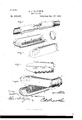
- Figure l is a perspective view of two ends of a rope showing the iinproved clamp applied thereto and as connecting said ends.
- Fig. 2 is a similar view of the parts of the rope-clamp detached.
- Fig. 3 is a side elevation of the clamp.
- Fig.4 is aperspective view showing the manner of applying the clamp to the rope-end.
- the numeral l designates two semi-cylindrical tubular shells or paris constituting the body of the clamp.
- the said parts are of duplicate construction and each has a series of spikes or spurs 2, projecting from the inner concave sides thereof.
- the rear ends of each of said shells or parts l are circumferentially grooved or channeled as at 3, and provided with rearward slightly iiaring lips 4, which are equally cut away, as at 5to provide for moving said lips closely toward each other in applying the clamp to a rope N.
- the circumferential groove or channel 3 is adapted to receive a half-round ring 6, or a ring of any other preferred construction, which is slipped over the lips 4, and when positioned within the channel or groove 3 is flush with the cylindrical surfaces of the shells or parts l, thereby avoiding projection and making the entire surface of the clamp substantially smooth and unbroken. It will also Serial No. 425,245. (No model.)
- each of the cylindrical shells or parts l are beveled or cut away, as at 7, and formed with eyes 8, whose front portions are rounded and thickened, as at 9,so that when the two parts are placed in contact with each other they simulate a portion of a ring and provide an increased bearing-surface, as will be readily understood.
- this clamp is especially adapted for use in connection with what is known as a bull rope of an oil-well drilling machine, which, as well understood in the art, travels over suitable pulleys adapted therefor.
- one section is first applied to the end of the rope, the latter having been previously bound by a suitable binding, and the spikes 2 thereof driven into the said rope Nbutleaving the beveled portion or front end of the said applied clamp part projecting beyond the end of the rope.
- the ring is slipped along the rope beyond the clamp.
- the second shell or part l is now applied and is tilted at an angle to bring the lip 4 thereof close against the rope in order that the ring 6 may be inserted or seated in the channel or groove 3.
- the said last-applied section is then forced against the rope N and the spikes or spurs 2 thereof also embedded in the said rope N. Owing to the connection of the parts by the ring 6,they assume an angle to each other, as fully shownA in Fig. 4, and the two ends of the bull-rope to which the devices are applied are then connected by passing a fastening through the eyes 8 of the two sets of clamps to thereby secure the opposite ends of the rope to each other.
- the beveled construction adjacent t0 the eyes S provides for a depression of the fastening connecting two oppositely-situated clamps in order that said fastening will not be engaged when the clamps pass around a pulley.
- a yielding ICO movement thereof is provided; and when the tension is increased on the rope to which the clamps are connected, the fastening securing two oppositely-situated clamps draws the cylindrical shells or parts l of each clamp toward each other and forces them more tightly against the rope N, thus increasing the biting action on the rope, and avoids disengagementorbreaking away of the clamp from the rope.
- this form of clamp maybe used in connection with other forms of ropes,if desired,and it maybe increased or diminished in size as found necessary for different purposes.
- the fastening is removed 'from the eye and each cylindrical shell or part is drawn back so as to disengage the spurs thereof from contact with the rope-end and the ring 6 can be readily slipped off owing to its loose engagement with the parts of the clamp.
- clamp as a whole may be constructed of any suitable kind of metal and in any preferred form, and
- each section or part of each clamp is a duplicate of the other, the formation of the same is rendered very simple, convenient, and comparatively inexpensive.
Landscapes
- Engineering & Computer Science (AREA)
- General Engineering & Computer Science (AREA)
- Mechanical Engineering (AREA)
- Ropes Or Cables (AREA)
Description
(No Mod-81,)
0.81. BALDWIN. ROPE CLAMP.
No. 488,848. Patented D80. 2o, 1882.
Nrran 'raras arrivi tinten.
OZBO J. BALDWIN, OF YOUNGSVILLE, PENNSYLVANIA.
ROPEHCLAIVI P.
SPECIFICATION forming part of Letters Patent No. 488,348, dated December 20, 1892.
Application iilerl March 17, 1892.
To all whom it may concern,.-
Be it known that I, OZRo J. BALDWIN, a citizen of the United States, residing at Youngsville, in the county of Warren and State of Pennsylvania, have invented a new and useful Rope-Clamp, of which the following is a specification.
This invention relates to rope-clamps especially adapted for employment with oil-drilling or analogous machinery, and consists in the construction and arrangement of the parts thereof as will be more fully hereinafter described and claimed.
The object of the invention is to provide a rope-clamp which may be conveniently employed in connecting the ends of what is known as the bull rope of an oil-Well drilling machine in such manner that the tension brought to bear on the clamp will regulate the degree of tightness of binding. In the drawings-Figure l is a perspective view of two ends of a rope showing the iinproved clamp applied thereto and as connecting said ends. Fig. 2 is a similar view of the parts of the rope-clamp detached. Fig. 3 is a side elevation of the clamp. Fig.4 is aperspective view showing the manner of applying the clamp to the rope-end.
Similar letters and numerals of reference indicate corresponding parts in the several views.
Referring to the drawings, the numeral l designates two semi-cylindrical tubular shells or paris constituting the body of the clamp. The said parts are of duplicate construction and each has a series of spikes or spurs 2, projecting from the inner concave sides thereof. The rear ends of each of said shells or parts l are circumferentially grooved or channeled as at 3, and provided with rearward slightly iiaring lips 4, which are equally cut away, as at 5to provide for moving said lips closely toward each other in applying the clamp to a rope N. The circumferential groove or channel 3 is adapted to receive a half-round ring 6, or a ring of any other preferred construction, which is slipped over the lips 4, and when positioned within the channel or groove 3 is flush with the cylindrical surfaces of the shells or parts l, thereby avoiding projection and making the entire surface of the clamp substantially smooth and unbroken. It will also Serial No. 425,245. (No model.)
be observed that the corners of the lips are rounded or cut away, whereby the shells may be held at an angle to each other and thus introduced into the rinng 6, and the two shells subsequently brouglit together securing the ring and forming one of the two parts of a rope clamp. The opposite ends of each of the cylindrical shells or parts l are beveled or cut away, as at 7, and formed with eyes 8, whose front portions are rounded and thickened, as at 9,so that when the two parts are placed in contact with each other they simulate a portion of a ring and provide an increased bearing-surface, as will be readily understood.
As has been heretofore stated,this clampis especially adapted for use in connection with what is known as a bull rope of an oil-well drilling machine, which, as well understood in the art, travels over suitable pulleys adapted therefor. In applying the clamp to opposite ends of said rope, one section is first applied to the end of the rope, the latter having been previously bound by a suitable binding, and the spikes 2 thereof driven into the said rope Nbutleaving the beveled portion or front end of the said applied clamp part projecting beyond the end of the rope. Before the other section is applied in position, or, in fact, before either section is applied as may be desired, the ring is slipped along the rope beyond the clamp. The second shell or part l is now applied and is tilted at an angle to bring the lip 4 thereof close against the rope in order that the ring 6 may be inserted or seated in the channel or groove 3. The said last-applied section is then forced against the rope N and the spikes or spurs 2 thereof also embedded in the said rope N. Owing to the connection of the parts by the ring 6,they assume an angle to each other, as fully shownA in Fig. 4, and the two ends of the bull-rope to which the devices are applied are then connected by passing a fastening through the eyes 8 of the two sets of clamps to thereby secure the opposite ends of the rope to each other. The beveled construction adjacent t0 the eyes S provides for a depression of the fastening connecting two oppositely-situated clamps in order that said fastening will not be engaged when the clamps pass around a pulley. Owing to the normal angular arrangement of each clamp-section, a yielding ICO movement thereof is provided; and when the tension is increased on the rope to which the clamps are connected, the fastening securing two oppositely-situated clamps draws the cylindrical shells or parts l of each clamp toward each other and forces them more tightly against the rope N, thus increasing the biting action on the rope, and avoids disengagementorbreaking away of the clamp from the rope. It is obviously apparent that this form of clamp maybe used in connection with other forms of ropes,if desired,and it maybe increased or diminished in size as found necessary for different purposes. When it is desired to releasethe clam p from a rope-end, the fastening is removed 'from the eye and each cylindrical shell or part is drawn back so as to disengage the spurs thereof from contact with the rope-end and the ring 6 can be readily slipped off owing to its loose engagement with the parts of the clamp.
It will be understood that the clamp as a whole may be constructed of any suitable kind of metal and in any preferred form, and
as each section or part of each clamp is a duplicate of the other, the formation of the same is rendered very simple, convenient, and comparatively inexpensive.
Having thus described the invention,-what is claimed as new is- In a rope clamp, the combination of the ring 6, and the two semi-cylindrical tubular shells provided internally with spurs, and having their rear ends circumferentially channeled or grooved,and cut away or rounded at the corners, whereby said shells may be held at an angle of inclination to each other and thus introduced into the ring, and the two shells subsequently brought together securing the ring and forming one of two parts of a rope clamp, substantially as described.
In testimony thatI claim the foregoing as my own I have hereto affixed my signature in the presence of two witnesses.
OZRO J. BALDWIN.
Vitnesses:
JOHN H. SIGGERs, HORACE G. PIERsoN.
Publications (1)
| Publication Number | Publication Date |
|---|---|
| US488348A true US488348A (en) | 1892-12-20 |
Family
ID=2557194
Family Applications (1)
| Application Number | Title | Priority Date | Filing Date |
|---|---|---|---|
| US488348D Expired - Lifetime US488348A (en) | Rope-c lamp |
Country Status (1)
| Country | Link |
|---|---|
| US (1) | US488348A (en) |
Cited By (1)
| Publication number | Priority date | Publication date | Assignee | Title |
|---|---|---|---|---|
| US2798749A (en) * | 1953-10-05 | 1957-07-09 | Herman Moe | Connector for two piece handles |
-
0
- US US488348D patent/US488348A/en not_active Expired - Lifetime
Cited By (1)
| Publication number | Priority date | Publication date | Assignee | Title |
|---|---|---|---|---|
| US2798749A (en) * | 1953-10-05 | 1957-07-09 | Herman Moe | Connector for two piece handles |
Similar Documents
| Publication | Publication Date | Title |
|---|---|---|
| US424388A (en) | Rope-clam p | |
| US1264230A (en) | Key for connecting machine parts. | |
| US319591A (en) | magee | |
| US334711A (en) | Eobeet loeenz | |
| US349147A (en) | Thomas p | |
| US521847A (en) | Eichard martin christensen | |
| US630868A (en) | Split pulley. | |
| US702416A (en) | Clamp. | |
| US419556A (en) | Milton | |
| US373183A (en) | Rope-fastening | |
| US831099A (en) | Packing. | |
| US469780A (en) | Coupling for shafts | |
| US738012A (en) | Teeth for sprocket wheels or gears. | |
| US955257A (en) | Clothes-line clip. | |
| US441757A (en) | Sash-balance | |
| US399489A (en) | Belt-fastener | |
| US686888A (en) | Rope-clamp. | |
| US875387A (en) | Tackle-block. | |
| US844704A (en) | Curtain-pole. | |
| US973654A (en) | Clamping device. | |
| US310104A (en) | Drive-chain | |
| US1088182A (en) | Rod or pipe clamp. | |
| US453515A (en) | Belt-fastener | |
| US1259715A (en) | Link belt or chain. | |
| US1004356A (en) | Belt-fastener. |