US4882286A - Digestion apparatus useful for a kjeldahl method - Google Patents
Digestion apparatus useful for a kjeldahl method Download PDFInfo
- Publication number
- US4882286A US4882286A US07/104,569 US10456987A US4882286A US 4882286 A US4882286 A US 4882286A US 10456987 A US10456987 A US 10456987A US 4882286 A US4882286 A US 4882286A
- Authority
- US
- United States
- Prior art keywords
- digestion
- reaction vessel
- connector tube
- microwave
- digestion apparatus
- Prior art date
- Legal status (The legal status is an assumption and is not a legal conclusion. Google has not performed a legal analysis and makes no representation as to the accuracy of the status listed.)
- Expired - Lifetime
Links
Images


Classifications
-
- G—PHYSICS
- G01—MEASURING; TESTING
- G01N—INVESTIGATING OR ANALYSING MATERIALS BY DETERMINING THEIR CHEMICAL OR PHYSICAL PROPERTIES
- G01N1/00—Sampling; Preparing specimens for investigation
- G01N1/28—Preparing specimens for investigation including physical details of (bio-)chemical methods covered elsewhere, e.g. G01N33/50, C12Q
- G01N1/44—Sample treatment involving radiation, e.g. heat
-
- B—PERFORMING OPERATIONS; TRANSPORTING
- B01—PHYSICAL OR CHEMICAL PROCESSES OR APPARATUS IN GENERAL
- B01J—CHEMICAL OR PHYSICAL PROCESSES, e.g. CATALYSIS OR COLLOID CHEMISTRY; THEIR RELEVANT APPARATUS
- B01J19/00—Chemical, physical or physico-chemical processes in general; Their relevant apparatus
- B01J19/08—Processes employing the direct application of electric or wave energy, or particle radiation; Apparatus therefor
- B01J19/12—Processes employing the direct application of electric or wave energy, or particle radiation; Apparatus therefor employing electromagnetic waves
- B01J19/122—Incoherent waves
- B01J19/126—Microwaves
-
- B—PERFORMING OPERATIONS; TRANSPORTING
- B01—PHYSICAL OR CHEMICAL PROCESSES OR APPARATUS IN GENERAL
- B01L—CHEMICAL OR PHYSICAL LABORATORY APPARATUS FOR GENERAL USE
- B01L3/00—Containers or dishes for laboratory use, e.g. laboratory glassware; Droppers
-
- G—PHYSICS
- G01—MEASURING; TESTING
- G01N—INVESTIGATING OR ANALYSING MATERIALS BY DETERMINING THEIR CHEMICAL OR PHYSICAL PROPERTIES
- G01N31/00—Investigating or analysing non-biological materials by the use of the chemical methods specified in the subgroup; Apparatus specially adapted for such methods
- G01N31/002—Determining nitrogen by transformation into ammonia, e.g. KJELDAHL method
-
- B—PERFORMING OPERATIONS; TRANSPORTING
- B01—PHYSICAL OR CHEMICAL PROCESSES OR APPARATUS IN GENERAL
- B01J—CHEMICAL OR PHYSICAL PROCESSES, e.g. CATALYSIS OR COLLOID CHEMISTRY; THEIR RELEVANT APPARATUS
- B01J2219/00—Chemical, physical or physico-chemical processes in general; Their relevant apparatus
- B01J2219/08—Processes employing the direct application of electric or wave energy, or particle radiation; Apparatus therefor
- B01J2219/12—Processes employing electromagnetic waves
- B01J2219/1203—Incoherent waves
- B01J2219/1206—Microwaves
- B01J2219/1209—Features relating to the reactor or vessel
- B01J2219/1212—Arrangements of the reactor or the reactors
- B01J2219/1215—Single reactor
-
- G—PHYSICS
- G01—MEASURING; TESTING
- G01N—INVESTIGATING OR ANALYSING MATERIALS BY DETERMINING THEIR CHEMICAL OR PHYSICAL PROPERTIES
- G01N33/00—Investigating or analysing materials by specific methods not covered by groups G01N1/00 - G01N31/00
- G01N33/02—Food
- G01N33/12—Meat; Fish
-
- Y—GENERAL TAGGING OF NEW TECHNOLOGICAL DEVELOPMENTS; GENERAL TAGGING OF CROSS-SECTIONAL TECHNOLOGIES SPANNING OVER SEVERAL SECTIONS OF THE IPC; TECHNICAL SUBJECTS COVERED BY FORMER USPC CROSS-REFERENCE ART COLLECTIONS [XRACs] AND DIGESTS
- Y10—TECHNICAL SUBJECTS COVERED BY FORMER USPC
- Y10T—TECHNICAL SUBJECTS COVERED BY FORMER US CLASSIFICATION
- Y10T436/00—Chemistry: analytical and immunological testing
- Y10T436/25—Chemistry: analytical and immunological testing including sample preparation
- Y10T436/25125—Digestion or removing interfering materials
Definitions
- the present invention relates to a microwave-based apparatus for rapid digestion, and to a rapid Kjeldahl digestion method.
- Kawasaki et al remove off gases through a hollow gas collector connected to an external scrubber and removably mounted, sample decomposing containers; and include an exhaust fan in the microwave oven thereof.
- Kawasaki et al describe a complex equation for selecting an irradiation time and an irradiation interruption period, to control foaming and bumping at an early stage of digestion.
- Prolabo's microwave digester vents gases through a container lid connected to a scrubber via a side arm.
- a protein sample is mixed with conventional Kjeldahl digestion ingredients, viz., 10-15 ml concentrated sulfuric acid, 0.75 g mercuric oxide catalyst and 15 g potassium sulfate; 10 ml hydrogen peroxide (35%) is combined with the mixture; the mixture is heated using a high flame; the mixture is heated with a low flame; and 110 ml deionized water is added to the digestate, while cooling the reaction vessel using a blower.
- this method Although fast compared to other Kjeldahl methods, this method nevertheless requires twelve minutes to produce a digested sample.
- the method uses a 0.5 sample when protein content is more than 45%, and a 1.0 g sample when protein content is less than 45%.
- the apparatus used in the method includes a scrubber connected to a side tube of the reaction vessel.
- a microwave-based apparatus for rapid digestion of a sample.
- the apparatus includes a microwave system having a wall with an aperture formed therethrough.
- a reaction vessel Disposed within the microwave system is a reaction vessel, a portion of which is surrounded by a vessel contour-conforming, microwave-transparent insulator.
- a connector tube Extending through the wall aperture is a connector tube that is in an air-tight sealing relationship with the reaction vessel.
- a scrubber Connected to an end of the connector tube exterior to the microwave system, is a scrubber.
- Also provided by the present invention is a rapid Kjeldahl digestion method.
- a rapid Kjeldahl digestion method there is placed within a microwave system a reaction vessel containing a protein sample to be digested, and a sufficient amount of Kjeldahl digestion ingredients suitable for effecting digestion.
- the reaction vessel is insulated by a microwave-transparent insulator.
- Sufficient microwave energy is applied to the contents of the reaction vessel to quickly attain an optimum Kjeldahl digestion temperature. Once the optimum temperature has been reached, sufficient microwave energy is applied to the vessel contents to maintain the optimum temperature until digestion is completed.
- off gases are removed from the reaction vessel. Thereafter, the application of microwave energy is discontinued, and, while continuing to remove off gases, the digestate is diluted with water.
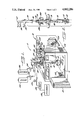
- FIG. 1 is a perspective, diagrammatic view of a preferred embodiment of a microwave-based, digestion apparatus in accordance with the present invention, with portions broken away;
- FIG. 2 is an exploded, perspective view of a portion of the apparatus of FIG. 1;
- FIG. 3 is an enlarged section taken along the line 3--3 in FIG. 1;
- FIG. 4 is a view similar to FIG. 3, with connector tube 36 in raised position;
- FIG. 5 is an enlarged section taken along the line 5--5 in FIG. 3.
- the present invention is directed to a microwave-based apparatus for rapid digestion, and to a rapid Kjeldahl digestion method using the apparatus.
- the terms “upper”, “lower”, “top”, “upward” and “downwardly” are intended to designate relative orientation as shown in the drawing.
- FIG. 1 depicts a preferred microwave-based, digestion apparatus 10 in accordance with the present invention.
- Apparatus 10 includes a microwave system 12 including an internal chamber 16 formed in part by a floor 17, a chamber ceiling 18, shown in FIG. 3, and a door 20.
- the inner surface of each wall forming the internal chamber is preferably corrosion resistant, for example, coated with a fluorocarbon resin such as Teflon®.
- a reaction vessel 22 Disposed in internal chamber 16 is a reaction vessel 22 having a neck 24 that terminates in an inwardly tapered mouth 26, shown best in FIG. 4. Mouth 25 has an inside wall 26 and an outside wall 27. It is preferred for the reaction vessel to be made of quartz glass.
- neck 24 ends in the inwardly ground mouth of a 29/42 ground glass joint, as a joint of this diameter enables a microslide cover glass bearing a sample, to be dropped into vessel 22.
- a flat bottom, boiling flask is a preferred reaction vessel.
- a lower portion 28 of the rounded part of the vessel is insulated by a cup 30.
- the cup is molded to conform to the contour of the lower portion of the vessel, and is made of a microwave-transparent insulator.
- the insulator is a moldable material able to withstand temperatures up to about 500° C. such as glass fiber.
- an upper region of the cup may be hand molded after the vessel has been inserted into the cup, so that the cup is completely conformed to the vessel contour.
- insulation may be provided around an upper portion 31 of the rounded part of the vessel, thereby insulating the entire vessel except for neck 24.
- a suitable glass fiber cup has a thickness of about 4.5 mm+/-1 mm.
- Microwave system 12 has a top wall 32, with an aperture 33 (shown in FIG. 5), advantageously having a diameter of about one-half inch, formed therethrough.
- An upper end 34 of a connector tube 36 extends through the aperture and protrudes above the top wall.
- a split bushing 38 suitably made of a heat-resistant material such as Telfon®, effects a snug fit between the connector tube and an exterior panel 39 of the top wall. As shown in FIG. 2, bushing 38 splits into two pieces 38A and 38B for assembly.
- Exterior to the top wall is a male joint 40 of upper end 34, which forms an air-tight friction seal with a female joint 42 of an input/output tree 44.
- tube 36 and tree 44 are made of glass, and joints 40,42 are tapered, ground glass joints.
- connector tube 36 has a rounded joint 46, preferably ground glass, at a bell-shaped, lower end 48 that is downwardly biased by springs 50,51 to form an air-tight seal with inwardly tapered mouth 25 (shown in FIG. 4) of the reaction vessel.
- the angle of inward taper of mouth 25 is adapted for sealingly mating with rounded joint 46.
- the angle of taper is about 45°.
- joint 46 prevents freezing of the connector tube/reaction vessel juncture, which may occur if joint 46 is provided with a conventional tapered shape.
- the rounded shape also makes it easy for an operator to sealingly mate vessel mouth 25 with the connector tube.
- upper spring ends 52,54 are attached to tree arms 56,58, respectively, and lower spring ends 60,62 attach to spring anchor clips 64,66, respectively.
- Screws 68,70 anchor the clips and a mounting bracket 72 to exterior panel 39.
- Mounting bracket 72 holds split bushing 38 in place.
- a connector tube shoulder 74 below male joint 40 seats on a flange 75 of bushing 38 to limit the downwardly biased movement of the connector tube.
- spring biasing of the connector tube/reaction vessel juncture permits upward movement of rounded joint 46, for ease of forming the air tight seal upon introducing vessel 22 into internal chamber 16, and for ease of removing the vessel when digestion is complete.
- RF stub 76 provides a radiation-tight seal between connector tube 36 and chamber ceiling 18. Stub 76 is secured to ceiling 18 by a washer 78 and a nut 80.
- tree 44 includes a pair of input tubes 82,84 that combine to form an inlet tube 86 that extends through connector tube 36.
- Inlet tube 86 is coaxially disposed within the connector tube.
- inlet tube 86 terminates in an upper part 88 of bell-shaped, lower end 48 of the connecting tube.
- An aperture 90 in the delivery end 92 of the inlet tube is disposed in an inlet tube side wall 94 so as to direct fluid flow against an inner wall surface 96 of bell-shaped, lower end 48.
- inlet tube 92 could have an open lower end.
- input tube 82 attached to input tube 82 is a section 98 of tubing that connects to a reservoir 100 containing, for example, aqueous hydrogen peroxide, and there is attached to input tube 84 a section 102 of tubing that connects to a reservoir 104 containing, for instance, water.
- the input lines from the reservoirs are regulated by one-way valves/solenoids 106,108, respectively.
- Tree 44 further includes a gas outlet tube 110. As shown in FIG. 3, extending from an opening 112 in rounded joint 46 of the connector tube to an outlet tube mouth 114 (shown in FIG. 5) is a passageway 116, through which off gases escape from the reaction vessel.
- a section 118 of tubing that connects to a scrubber 120 via a valve 122 that opens to the ambient atmosphere, and a trap 124.
- Polyethylene tubing is useful for tubing sections 98,102.
- tubing section 118 should be of a heat-resistant material such as Teflon®, up to valve 122.
- Microwave system 12 includes a corrosion resistant blower 126 and air intake panels 128,130 for flow of air through internal chamber 16.
- the blower is capable of providing high volume air flow through the chamber.
- high volume air flow is meant on the order of 100 scfm or higher.
- Microwave system 12 further includes a magnetron 132, a wave guide 134 and a radiation mixer 136.
- a radiation isolator 138 is advantageously located in the wave guide, for absorbing excess reflected radiation to prevent damaging reflection back to the magnetron.
- the isolator includes magnetic shapes coupled with heat sinks. The isolator permits originating microwaves emitted from the magnetron to pass through unaffected, but absorbs reflected waves. The isolator has a propensity for attracting reflected radiation and thus will tend to draw reflected radiation out of the internal chamber.
- the isolator converts the reflected radiation to heat, which is dissipated through an isolator heat exchanger 140.
- a heat exchanger duct 142 communicates with the heat exchanger and a fan 144, which draws off the produced heat.
- the fan and the isolator are able to absorb the full capacity of reflected energy for a zero load, for prolonged, indefinite operation.
- the novel microwave-based, digestion apparatus of the present invention is used in a unique Kjeldahl digestion method as now described.
- the amounts of the various ingredients and the particular times included in the below description, are for a 0.5 g protein sample containing 45% or more protein. Twice as large a protein sample is used when the sample includes less than 45% protein.
- the protein sample preferably either a 0.5 g or 1.0 g sample depending upon the % protein, is added to reaction vessel 22, with conventional Kjeldahl digestion ingredients, to wit, about 10-15 ml of concentrated sulfuric acid, about 0.75 g of mercuric oxide, and about 15 g of potassium sulfate.
- the insulated vessel is placed in internal chamber 16 of microwave system 12, which has a power output of 730 watts, an air-tight seal is formed between the vessel and the connector tube, and the microwave door is closed.
- the vertically disposed connector tube reduces the boil-over problem.
- a boil-over reducing additive such as aqueous hydrogen peroxide solution
- a boil-over reducing additive is added to the reaction vessel, advantageously with scrubber 120 turned on due to resultant fuming and heat generation.
- the additive is injected through inlet tube 86 into the reaction vessel in an amount sufficient to reduce boil-over.
- a highly preferred 40% hydrogen peroxide solution is sulfuric acid-stabilized, and is prepared by mixing 1 part of concentrated sulfuric acid with 4 parts of 50% hydrogen peroxide. Hydrogen peroxide may assist rapid digestion.
- a digestion step may be immediately begun by the application of microwave energy to the vessel contents.
- the vessel contents are heated to quickly attain an optimum digestion temperature generally ranging from about 375° to 410° C. Gas generation with resultant foaming and/or bumping, characterizes this heating stage. Overshooting the optimum temperature results in an erroneously lower protein number.
- the optimum temperature is quickly reached by using a 100% power output for approximately 1.5-1.75 minutes.
- minutes would be added to this stage of the digestion step due to heat loss through the reaction vessel walls.
- the number of samples that can be simultaneously digested is power limited.
- the power output is adjusted to maintain the optimum digestion temperature until digestion is complete. This step is typically accomplished by heating the vessel contents using 70% power for about 2.5 minutes.
- blower 126 it is preferred for blower 126 to be on at all times during the novel method of the present invention.
- the blower provides a cooling effect as air passes over the uninsulated upper portion of the reaction vessel, and over the part of the connector tube within internal chamber 16.
- the blower reduces the loss of acid, as off gases of the digestion step are cooled to cause acid condensation and return of condensed acid to the reaction vessel. It will be appreciated that this advantage may be fully realized even if the blower is not turned on until the beginning of the digestion step, and may achieved to a lesser extent if the blower is not turned on until the beginning of the second heating stage.
- vessel contents L in FIG. 3 represent the contents level in a 500 ml reaction vessel prior to beginning the digestion step.
- a dilution step may be immediately commenced.
- water is injected into the reaction vessel via the water input line through inlet tube 86. Mixing of the water with the hot digestate quickly results in the evolution of a large volume of gas. However, in a short time, cooling produced by the water, creates a negative pressure within the reaction vessel.
- FIG. 3 represents the contents level in a 500 ml reaction vessel after the dilution step. It is intended that the insulator cover the vessel to above this level.
- a pulsed addition of water is preferably employed.
- a highly preferred pulsing technique involves intermittently opening and closing the water input line until sufficient water has been added that there is a controlled gas evolution, that is, a gas evolution that does not cause a mechanical bumping in which the connector tube/reaction vessel joint momentarily opens and closes as a result of which off gas escapes through the joint.
- a controlled gas evolution that is, a gas evolution that does not cause a mechanical bumping in which the connector tube/reaction vessel joint momentarily opens and closes as a result of which off gas escapes through the joint.
- a cooling step should be used to control the sudden surge in gas evolution.
- a cooldown period of from about 20 seconds to one minute is useful.
- a large, sudden evolution of gas may cause mechanical bumping. It will be understood that a cooldown period of about several minutes or longer could be employed to minimize the likelihood of mechanical bumping, but that the overall time of carrying out the method would be substantially increased.
- Pre-heating of the water may further control gas evolution.
- the water is pre-heated as opening 90 in the inlet tube directs the water against connector tube inner wall surface 96, and the water flows down the inner wall into vessel 22.
- the scrubber and blower are turned off, the reaction vessel is removed from the microwave system, and the digestate is analyzed.
- a particularly suitable material for the reaction vessel is borosilicate glass or quartz glass.
- a quartz vessel advantageously is more microwave transparent, thereby providing a relatively shorter digestion time, the power output being constant. Furthermore, a quartz vessel withstands thermal shock better. Moreover, with a sample containing more than about 30% protein, especially 45% or more protein, a quartz vessel surprisingly yields more accurate results.
- scrubber 120 may be off until the beginning of the second heating stage, and furthermore when turned on, may be regulated to provide a negative pressure less than the positive pressure generated by the off gases.
- This variation permits positive pressure build up and causes an overall positive pressure to be maintained upstream from trap 124, thereby making boil-over even more unlikely.
- valve 122 remains closed until a negative pressure is produced within the reaction vessel during the dilution step.
- a 1.0 g sample of meat is weighed out on a 24 ⁇ 40 microslide cover glass and dropped through a 29/42 ground glass joint of the neck of quartz, flat bottom, boiling flask 22 (500 ml). 10 ml of concentrated sulfuric acid, 0.75 g of mercuric oxide and 15 g of potassium sulfate are added to the flask.
- Lower portion 28 of the flask is insulated by a molded, glass fiber cup 30 having a thickness of 4.5 mm+/-1 mm.
- the insulated flask is placed in internal chamber 16 of microwave 12, flask mouth 25 is sealingly mated to rounded joint 46 of the connector tube, and the microwave door is closed.
- the scrubber and blower are turned off, the reaction flask is removed from the microwave, and the digestate is analyzed for percent protein.
- the microwave-based apparatus of the present invention is useful for rapid sample digestion.
Landscapes
- Health & Medical Sciences (AREA)
- Chemical & Material Sciences (AREA)
- General Health & Medical Sciences (AREA)
- Life Sciences & Earth Sciences (AREA)
- Physics & Mathematics (AREA)
- General Physics & Mathematics (AREA)
- Biochemistry (AREA)
- Analytical Chemistry (AREA)
- Immunology (AREA)
- Pathology (AREA)
- Chemical Kinetics & Catalysis (AREA)
- Molecular Biology (AREA)
- Clinical Laboratory Science (AREA)
- Electromagnetism (AREA)
- Toxicology (AREA)
- Organic Chemistry (AREA)
- Processing Of Solid Wastes (AREA)
Abstract
Description
Claims (10)
Priority Applications (1)
| Application Number | Priority Date | Filing Date | Title |
|---|---|---|---|
| US07/104,569 US4882286A (en) | 1986-06-13 | 1987-10-02 | Digestion apparatus useful for a kjeldahl method |
Applications Claiming Priority (2)
| Application Number | Priority Date | Filing Date | Title |
|---|---|---|---|
| US87427886A | 1986-06-13 | 1986-06-13 | |
| US07/104,569 US4882286A (en) | 1986-06-13 | 1987-10-02 | Digestion apparatus useful for a kjeldahl method |
Related Parent Applications (1)
| Application Number | Title | Priority Date | Filing Date |
|---|---|---|---|
| US87427886A Continuation | 1986-06-13 | 1986-06-13 |
Publications (1)
| Publication Number | Publication Date |
|---|---|
| US4882286A true US4882286A (en) | 1989-11-21 |
Family
ID=26801691
Family Applications (1)
| Application Number | Title | Priority Date | Filing Date |
|---|---|---|---|
| US07/104,569 Expired - Lifetime US4882286A (en) | 1986-06-13 | 1987-10-02 | Digestion apparatus useful for a kjeldahl method |
Country Status (1)
| Country | Link |
|---|---|
| US (1) | US4882286A (en) |
Cited By (21)
| Publication number | Priority date | Publication date | Assignee | Title |
|---|---|---|---|---|
| DE4108766A1 (en) * | 1991-03-18 | 1992-09-24 | Guenter Knapp | High pressure microwave heating appts. - for long term high temp. acid dissolution of substances |
| US5314664A (en) * | 1991-04-03 | 1994-05-24 | Bodenseewerk Perkin-Elmer Gmbh | Sample supply system having integrated microwave disintegration |
| US5318754A (en) * | 1983-04-21 | 1994-06-07 | Cem Corporation | Microwave ashing apparatuses and components |
| US5427741A (en) * | 1993-05-19 | 1995-06-27 | Cem Corporation | Pressure resistant reinforcing means for containers for materials to be microwave heated |
| US5711857A (en) * | 1995-10-12 | 1998-01-27 | Armstrong; Bernard | Microwave distillation apparatus |
| US5939614A (en) * | 1998-07-01 | 1999-08-17 | Mt Systems, Llc | Chromatographic column for microwave heating |
| US5988877A (en) * | 1997-09-15 | 1999-11-23 | C E M Corporation | Method and apparatus for temperature calibration in microwave assisted chemistry |
| US6011247A (en) * | 1997-03-03 | 2000-01-04 | Questron Canada Inc. | System for open and closed vessel microwave chemistry |
| US6086826A (en) * | 1997-09-15 | 2000-07-11 | Cem Corporation | Pressure sensing reaction vessel for microwave assisted chemistry |
| US6092924A (en) * | 1998-02-10 | 2000-07-25 | Denver Instrument Company | Microwave moisture analyzer: apparatus and method |
| US6093921A (en) * | 1999-03-04 | 2000-07-25 | Mt Systems, Llc | Microwave heating apparatus for gas chromatographic columns |
| US6247246B1 (en) | 1998-05-27 | 2001-06-19 | Denver Instrument Company | Microwave moisture analyzer: apparatus and method |
| US6294772B1 (en) * | 1998-09-04 | 2001-09-25 | Cem Corporation | Microwave probe applicator for physical and chemical processes |
| US6316759B2 (en) | 1999-03-04 | 2001-11-13 | Mt Systems, Llc | Microwave heating apparatus for gas chromatographic columns |
| US6630652B2 (en) * | 2001-01-31 | 2003-10-07 | Cem Corporation | Microwave-assisted chemical synthesis instrument with fixed tuning |
| US6729369B2 (en) | 1998-07-31 | 2004-05-04 | Chata Biosystems, Inc. | Vessel for containing/transporting a fluent substance |
| US20040187340A1 (en) * | 2003-01-21 | 2004-09-30 | Farid Chemat | Solvent-free microwave extraction of volatile natural substances |
| EP2031366A2 (en) | 2007-08-29 | 2009-03-04 | CEM Corporation | Automated protein analyzer |
| EP2031401A1 (en) | 2007-08-29 | 2009-03-04 | CEM Corporation | Automated protein analysis method |
| EP2108936A1 (en) | 2006-02-24 | 2009-10-14 | CEM Corporation | Filtration apparatus and associated method for microwave-assisted chemistry |
| US20110036705A1 (en) * | 2009-08-14 | 2011-02-17 | Barclay David A | Pressure stepped microwave assisted digestion |
Citations (14)
| Publication number | Priority date | Publication date | Assignee | Title |
|---|---|---|---|---|
| FR1045341A (en) * | 1951-11-21 | 1953-11-25 | Improvements made to burettes or other devices in glass or transparent material, graduated or not | |
| US2868626A (en) * | 1956-06-18 | 1959-01-13 | Upjohn Co | Semi-micro evaporation apparatus |
| US2932558A (en) * | 1958-02-05 | 1960-04-12 | Lab Equipment Corp | Hydrogen analysis |
| US3437211A (en) * | 1967-06-06 | 1969-04-08 | Marvin H Lindsey | Vacuum filtration device |
| GB1385483A (en) * | 1971-02-12 | 1975-02-26 | Smith R C | Chemical extraction vessel |
| US3963420A (en) * | 1972-08-31 | 1976-06-15 | Nippon Steel Corporation | Method and apparatus for automatically dissolving samples for anaylsis |
| US4080168A (en) * | 1976-02-18 | 1978-03-21 | The Curators Of The University Of Missouri | Method and apparatus for the wet digestion of organic and biological samples |
| US4307277A (en) * | 1978-08-03 | 1981-12-22 | Mitsubishi Denki Kabushiki Kaisha | Microwave heating oven |
| US4315573A (en) * | 1980-10-06 | 1982-02-16 | Owens-Illinois, Inc. | Method of strengthening glass containers and articles so made |
| US4347216A (en) * | 1980-06-30 | 1982-08-31 | Mitsubishi Kasei Kogyo Kabushiki Kaisha | Wet sample decomposing apparatus |
| US4363639A (en) * | 1981-03-09 | 1982-12-14 | Iowa State University Research Foundation, Inc. | Gas trap for removing atmospheric pollutants and method of operation |
| US4364753A (en) * | 1977-10-18 | 1982-12-21 | Linde Ag | Apparatus for the adsorptive cleaning of gases |
| US4490287A (en) * | 1976-07-29 | 1984-12-25 | United Kingdom Atomic Energy Authority | Treatment of substances |
| US4681740A (en) * | 1984-03-02 | 1987-07-21 | Societe Prolabo | Apparatus for the chemical reaction by wet process of various products |
-
1987
- 1987-10-02 US US07/104,569 patent/US4882286A/en not_active Expired - Lifetime
Patent Citations (14)
| Publication number | Priority date | Publication date | Assignee | Title |
|---|---|---|---|---|
| FR1045341A (en) * | 1951-11-21 | 1953-11-25 | Improvements made to burettes or other devices in glass or transparent material, graduated or not | |
| US2868626A (en) * | 1956-06-18 | 1959-01-13 | Upjohn Co | Semi-micro evaporation apparatus |
| US2932558A (en) * | 1958-02-05 | 1960-04-12 | Lab Equipment Corp | Hydrogen analysis |
| US3437211A (en) * | 1967-06-06 | 1969-04-08 | Marvin H Lindsey | Vacuum filtration device |
| GB1385483A (en) * | 1971-02-12 | 1975-02-26 | Smith R C | Chemical extraction vessel |
| US3963420A (en) * | 1972-08-31 | 1976-06-15 | Nippon Steel Corporation | Method and apparatus for automatically dissolving samples for anaylsis |
| US4080168A (en) * | 1976-02-18 | 1978-03-21 | The Curators Of The University Of Missouri | Method and apparatus for the wet digestion of organic and biological samples |
| US4490287A (en) * | 1976-07-29 | 1984-12-25 | United Kingdom Atomic Energy Authority | Treatment of substances |
| US4364753A (en) * | 1977-10-18 | 1982-12-21 | Linde Ag | Apparatus for the adsorptive cleaning of gases |
| US4307277A (en) * | 1978-08-03 | 1981-12-22 | Mitsubishi Denki Kabushiki Kaisha | Microwave heating oven |
| US4347216A (en) * | 1980-06-30 | 1982-08-31 | Mitsubishi Kasei Kogyo Kabushiki Kaisha | Wet sample decomposing apparatus |
| US4315573A (en) * | 1980-10-06 | 1982-02-16 | Owens-Illinois, Inc. | Method of strengthening glass containers and articles so made |
| US4363639A (en) * | 1981-03-09 | 1982-12-14 | Iowa State University Research Foundation, Inc. | Gas trap for removing atmospheric pollutants and method of operation |
| US4681740A (en) * | 1984-03-02 | 1987-07-21 | Societe Prolabo | Apparatus for the chemical reaction by wet process of various products |
Non-Patent Citations (7)
| Title |
|---|
| Bradstreet, The Kjeldahl Method for Organic Nitrogen, 1965, pp. 40 42. * |
| Bradstreet, The Kjeldahl Method for Organic Nitrogen, 1965, pp. 40-42. |
| Kjel Foss Automatic Literature by A/S N. Foss Electric. * |
| Kjel-Foss Automatic Literature by A/S N. Foss Electric. |
| P. Barrett et al, Analytical Chemistry, 7, 1021 (1978), Prolabo Literature. * |
| S. Brayton of the Hach Company, "A Practical Kjeldahl-Nitrogen Method". |
| S. Brayton of the Hach Company, A Practical Kjeldahl Nitrogen Method . * |
Cited By (47)
| Publication number | Priority date | Publication date | Assignee | Title |
|---|---|---|---|---|
| US5318754A (en) * | 1983-04-21 | 1994-06-07 | Cem Corporation | Microwave ashing apparatuses and components |
| US5345066A (en) * | 1991-03-18 | 1994-09-06 | Knapp Guenter | Device for heating substances under the development of high pressures in a microwave field |
| DE4108766A1 (en) * | 1991-03-18 | 1992-09-24 | Guenter Knapp | High pressure microwave heating appts. - for long term high temp. acid dissolution of substances |
| US5314664A (en) * | 1991-04-03 | 1994-05-24 | Bodenseewerk Perkin-Elmer Gmbh | Sample supply system having integrated microwave disintegration |
| US5427741A (en) * | 1993-05-19 | 1995-06-27 | Cem Corporation | Pressure resistant reinforcing means for containers for materials to be microwave heated |
| US6015968A (en) * | 1995-10-12 | 2000-01-18 | Armstrong; Bernard | Microwave distillation apparatus, and vessel-biasing assembly |
| US5711857A (en) * | 1995-10-12 | 1998-01-27 | Armstrong; Bernard | Microwave distillation apparatus |
| US6011247A (en) * | 1997-03-03 | 2000-01-04 | Questron Canada Inc. | System for open and closed vessel microwave chemistry |
| US5988877A (en) * | 1997-09-15 | 1999-11-23 | C E M Corporation | Method and apparatus for temperature calibration in microwave assisted chemistry |
| US6086826A (en) * | 1997-09-15 | 2000-07-11 | Cem Corporation | Pressure sensing reaction vessel for microwave assisted chemistry |
| US6124582A (en) * | 1997-09-15 | 2000-09-26 | Cem Corporation | Pressure sensing reaction vessel for microwave assisted chemistry |
| US6246038B1 (en) | 1997-09-15 | 2001-06-12 | Cem Limited, Llc | Pressure sensing reaction vessel for microwave assisted chemistry |
| US6092924A (en) * | 1998-02-10 | 2000-07-25 | Denver Instrument Company | Microwave moisture analyzer: apparatus and method |
| US6247246B1 (en) | 1998-05-27 | 2001-06-19 | Denver Instrument Company | Microwave moisture analyzer: apparatus and method |
| US7148455B2 (en) | 1998-05-27 | 2006-12-12 | Denver Instrument Company | Microwave moisture analyzer: apparatus and method |
| US6029498A (en) * | 1998-07-01 | 2000-02-29 | Mt Systems, Llc | Chromatographic column for microwave heating |
| US5939614A (en) * | 1998-07-01 | 1999-08-17 | Mt Systems, Llc | Chromatographic column for microwave heating |
| US6729369B2 (en) | 1998-07-31 | 2004-05-04 | Chata Biosystems, Inc. | Vessel for containing/transporting a fluent substance |
| US6294772B1 (en) * | 1998-09-04 | 2001-09-25 | Cem Corporation | Microwave probe applicator for physical and chemical processes |
| US6316759B2 (en) | 1999-03-04 | 2001-11-13 | Mt Systems, Llc | Microwave heating apparatus for gas chromatographic columns |
| US6157015A (en) * | 1999-03-04 | 2000-12-05 | Mt Systems, Llc | Microwave heating apparatus for gas chromatographic columns |
| US6093921A (en) * | 1999-03-04 | 2000-07-25 | Mt Systems, Llc | Microwave heating apparatus for gas chromatographic columns |
| US6630652B2 (en) * | 2001-01-31 | 2003-10-07 | Cem Corporation | Microwave-assisted chemical synthesis instrument with fixed tuning |
| US6713739B2 (en) | 2001-01-31 | 2004-03-30 | Cem Corporation | Microwave-assisted chemical synthesis instrument with fixed tuning |
| US20040187340A1 (en) * | 2003-01-21 | 2004-09-30 | Farid Chemat | Solvent-free microwave extraction of volatile natural substances |
| EP2108936A1 (en) | 2006-02-24 | 2009-10-14 | CEM Corporation | Filtration apparatus and associated method for microwave-assisted chemistry |
| US20110084035A1 (en) * | 2006-02-24 | 2011-04-14 | Cem Corporation | Filtration Apparatus and Associated Method for Microwave-Assisted Chemistry |
| EP2031366A2 (en) | 2007-08-29 | 2009-03-04 | CEM Corporation | Automated protein analyzer |
| EP2031400A1 (en) | 2007-08-29 | 2009-03-04 | CEM Corporation | Automated Protein Analysis method |
| US20090061522A1 (en) * | 2007-08-29 | 2009-03-05 | Collins Sr Michael J | Automated Protein Analyzer |
| US20090087917A1 (en) * | 2007-08-29 | 2009-04-02 | Cem Corporation | Automated protein analyzer |
| EP2053404A1 (en) | 2007-08-29 | 2009-04-29 | CEM Corporation | Automated protein analysis kit |
| EP2031399A1 (en) | 2007-08-29 | 2009-03-04 | CEM Corporation | Automated protein analysis method |
| US20100290949A1 (en) * | 2007-08-29 | 2010-11-18 | Cem Corp. | Automated protein analyzer |
| US20100291686A1 (en) * | 2007-08-29 | 2010-11-18 | Cem Corp. | Automated protein analyzer |
| EP3435086A2 (en) | 2007-08-29 | 2019-01-30 | CEM Corporation | Automated protein analyzer |
| EP2031401A1 (en) | 2007-08-29 | 2009-03-04 | CEM Corporation | Automated protein analysis method |
| US7968344B2 (en) | 2007-08-29 | 2011-06-28 | Cem Corporation | Automated protein analyzer |
| US8147759B2 (en) | 2007-08-29 | 2012-04-03 | Cem Corporation | Automated protein analyzer |
| US8663993B2 (en) | 2007-08-29 | 2014-03-04 | Cem Corporation | Automated protein analyzer |
| US8852948B2 (en) | 2007-08-29 | 2014-10-07 | Cem Corporation | Colorimetric protein analysis method |
| US9091632B2 (en) | 2007-08-29 | 2015-07-28 | Cem Corporation | Automated protein analyzer |
| US9237608B2 (en) | 2009-08-14 | 2016-01-12 | Cem Corporation | Pressure stepped microwave assisted digestion |
| US9943823B2 (en) | 2009-08-14 | 2018-04-17 | Cem Corporation | Pressure stepped microwave assisted digestion |
| US10067043B2 (en) | 2009-08-14 | 2018-09-04 | Cem Corporation | Pressure stepped microwave assisted digestion |
| US20110036705A1 (en) * | 2009-08-14 | 2011-02-17 | Barclay David A | Pressure stepped microwave assisted digestion |
| US10527530B2 (en) | 2009-08-14 | 2020-01-07 | Cem Corporation | Pressure stepped microwave assisted digestion |
Similar Documents
| Publication | Publication Date | Title |
|---|---|---|
| US4882286A (en) | Digestion apparatus useful for a kjeldahl method | |
| US4861556A (en) | Microwave-based apparatus and Kjeldahl method | |
| US4946797A (en) | Microwave-based Kjeldahl method | |
| EP0155893B1 (en) | Device for chemical reaction of various chemicals by wet method | |
| US4347216A (en) | Wet sample decomposing apparatus | |
| US5369034A (en) | Use of a ventable rupture diaphragm-protected container for heating contained materials by microwave radiation | |
| EP0198675A2 (en) | Self-regulating valve in a microwave system and a lidded vessel | |
| KR960015436B1 (en) | Tube having regions of different surface chemistry and method therefor | |
| DE3877288D1 (en) | EPITAXY SYSTEM. | |
| JPS63501535A (en) | Method and apparatus for reducing the viscosity of highly viscous materials | |
| AU717716B2 (en) | Microwave pressure vessel and method of sterilization | |
| WO1995019189A1 (en) | Microwave powered steam pressure generator | |
| Dunemann et al. | Comparison of different microwave-based digestion techniques in view of their application to fat-rich foods | |
| CN219391263U (en) | Hydrogen leakage monitoring device of hydrogen station | |
| JPS6372336A (en) | Method and device for kjeldahl decomposition | |
| CN208906064U (en) | A kind of UV reactive case being used to prepare antibacterial, anticoagulant dressing | |
| Moralesrubio et al. | Rapid acid hydrolysis of albumin in a microwave oven | |
| JPH05509260A (en) | Devices that can fit into containers, especially containers for chemical reactions, and reactors containing such devices and uses thereof | |
| CN208459077U (en) | A kind of vacuum sampler | |
| US20250379068A1 (en) | Chip defect modifying device and method | |
| Pougnet | Modification of a commercial microwave oven for applications in the chemical laboratory | |
| JPH03106485A (en) | Ultrasonic washing and drying method and apparatus | |
| CN209356288U (en) | A high-voltage device for antigen retrieval | |
| CN215288048U (en) | Novel be convenient for sewage treatment who removes device | |
| Patterson | Oxygen plasma asher |
Legal Events
| Date | Code | Title | Description |
|---|---|---|---|
| STCF | Information on status: patent grant |
Free format text: PATENTED CASE |
|
| FEPP | Fee payment procedure |
Free format text: PAYOR NUMBER ASSIGNED (ORIGINAL EVENT CODE: ASPN); ENTITY STATUS OF PATENT OWNER: SMALL ENTITY |
|
| FPAY | Fee payment |
Year of fee payment: 4 |
|
| FEPP | Fee payment procedure |
Free format text: PAYOR NUMBER ASSIGNED (ORIGINAL EVENT CODE: ASPN); ENTITY STATUS OF PATENT OWNER: SMALL ENTITY Free format text: PAYER NUMBER DE-ASSIGNED (ORIGINAL EVENT CODE: RMPN); ENTITY STATUS OF PATENT OWNER: SMALL ENTITY |
|
| FPAY | Fee payment |
Year of fee payment: 8 |
|
| AS | Assignment |
Owner name: BANC OF AMERICA COMMERCIAL FINANCE CORPORATION, AS Free format text: NOTICE OF GRANT OF SECURITY INTEREST;ASSIGNOR:CEM LIMITED, LLC;REEL/FRAME:010892/0430 Effective date: 20000531 |
|
| AS | Assignment |
Owner name: CEM LIMITED, L.L.C., NORTH CAROLINA Free format text: ASSIGNMENT OF ASSIGNORS INTEREST;ASSIGNOR:CEM CORPORATION;REEL/FRAME:010892/0674 Effective date: 20000531 |
|
| FPAY | Fee payment |
Year of fee payment: 12 |
|
| AS | Assignment |
Owner name: CEM CORPORATION, NORTH CAROLINA Free format text: MERGER;ASSIGNOR:CEM LIMITED, LLC;REEL/FRAME:013248/0680 Effective date: 20001020 |