BACKGROUND AND OBJECTS OF THE INVENTION
The invention concerns a bench type cutter of the type in which a cutting tool is mounted on a work bench. The tool is affixed to a tool axle, the ends of which are rotatably held in upper and lower legs, respectively, of a bearing assembly. A connector portion of the bearing assembly interconnects the legs and passes through a passage in the work bench.
A bench type milling cutter of this type is known from DE-OS 33 37 265 in which a milling cutter is attached to a vertical axle, the axle being rotatably mounted in upper and lower bearings. The lower bearing is mounted on a lower bearing holder carried by the lower horizontal leg of a U-shaped bearing block. The upper bearing is attached to an upper horizontal leg of the bearing block. The bearing block is attached pivotably to a base, the latter being affixed to the underside of a horizontal workbench table. The bearing block is thus rotatably about a horizontal axis to enable the inclination of the axle to be varied. By raising and lowering the height of the lower bearing holder relative to the upper leg, the height at which the milling tool is disposed above the table can be varied. A disadvantage of such structure involves the fact that all adjusting operations, such as the setting of the inclination angle, and the adjustment of the tool height is possible only by the actuation of devices located under the table. This is cumbersome and expensive.
It is the object of the invention to provide a bench type milling cutter of the afore-mentioned type such that the setting and working conditions are simplified. This object is attained in the case of a bench type milling cutter of the afore-mentioned type wherein a bearing block assembly is carried by a carrier and is linearly vertically adjustable relative to the carrier by means of a manual actuator. The carrier, in turn, is mounted on a base for rotation relative to the base within a vertical plane containing the tool axis, such rotation created by a manual actuator. By means of this arrangement, in which the adjusting controls for the milling assembly are no longer located under the table but rather are more readily accessible, it is possible in a simplified manner to actuate the controls from above the work bench, especially for adjusting the height of the milling cutter. A more simplified operation, also making possible more accurate milling operations, is thereby created.
Preferably, the base comprises a slide which is movable horizontally relative to the work bench so that the tool may be displaced horizontally in relation to the workpiece so that processing that is not possible with the known bench type milling tools, may be carried out without reclamping the workpiece.
THE DRAWINGS
The objects and advantages of the invention will become apparent from the following detailed description of a preferred embodiment thereof in connection with the accompanying drawings in which like numerals designate like elements, and in which:
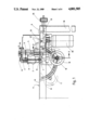
FIG. 1 is a schematic lateral elevational view of a bench type milling cutter according to the invention;
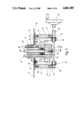
FIG. 2 is a vertical section through the bench type milling cutter taken along the line II--II of FIG. 1, with parts of the assembly broken away;
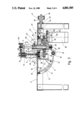
FIG. 3 is a vertical sectional view through the milling cutter taken along the line III--III of FIG. 2;
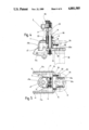
FIG. 4 is a vertical sectional view through a portion of the apparatus including the bearing assembly and carrier; and
FIG. 5 is a plan view of the sliding piece of FIG. 4.
DETAILED DESCRIPTION OF A PREFERRED EMBODIMENT OF THE INVENTION
It is seen from FIG. 1 that the novel bench type milling cutter comprises a work bench (6), a horizontal work table (6A) of which is supported in a known manner by means of column legs on the ground. The table is able to support a workpiece (not shown). Mounted to the work bench is a tool-carrying module comprising a base or slide (10), a carrier (17), and a bearing assembly (3, 4, 14, 15) as will be explained hereinafter. The slide (10) is located adjacent the underside of the table and is horizontally linearly displaceable in a direction parallel to the plane of the table (6A). The slide includes a guide plate (37) and downwardly depending jaws (12) arranged parallel to each other. The slide (10) constructed in this manner is held displaceably on the bottom side of the table (6A) by screws (38) mounted in the table (6A). The screws project through guide slots (27) in the plate (37), thereby enabling the plate (37) to be displaceable relative to the bench (6) in the direction of the guide slots (27). A clamping plate (39) is pressed against the plate (37) by nuts to hold the plate (37) in adjusted positions. The guide plate (37) is provided on one end with a rim (40) on which an adjusting spindle (25) is fixedly mounted with its axle parallel to the plate (37). This adjusting spindle (25) is received threadedly in an adjusting nut (26), which is supported rotatingly on an outer edge of the work bench (6) and is equipped with knurling (41) for manual actuation. The afore-mentioned linear displacement of the slide (10) may therefore be effected by rotating the adjusting nut (26).
Between the two jaws (12), a sliding piece or carrier (17) is movably guided. The carrier (17) has two legs (42) abutting tightly against the jaws (12) of the slide (10). Outwardly directed curved projections (43) of the carrier engage guide slots (11) formed in the inner side of the jaws (12). Each guide slot (11) has the configuration of a circular arc as depicted in FIG. 3. The center of curvature (13) of the slots (11) defines a pivot axis for the carrier (17), which axis preferably lies on the surface of the table (6A).
Guide sleeves (16) are fixedly connected to the carrier (17). Rods (14, 15) are slidably guided without radial clearance in the sleeves. The lower ends of the rods (15) are fixedly connected to a yoke-like body forming part of a lower leg or head (4) of the bearing assembly, as described in more detail below.
The upper ends of the rods (14 and 15) are fixedly connected with an upper leg or head (3) which has the configuration of a yoke. The rods (14, 15) pass through a passage (35) in the table (6A).
The lower bearing head (4) carries a lower bearing (44A) which holds a milling spindle (28). The spindle is drawn upwardly by a threaded bolt (45). The bolt (45) also presses an axially displaceable stub shaft (44) tightly against the milling tool (2) and presses the latter simultaneously against a suitable cone (46) of the milling spindle (28), to entrain the tool for rotation with the spindle. The stub shaft (44) is held in a suitable bearing (44B) in the upper leg (3). The bolt (45), spindle (28), and stub shaft (44) form a tool axle assemble which is driven about an axis (8) by a drive mechanism. In that regard, the lower bearing head (4) is extended downwards in the manner of a skirt and has lateral walls (47) surrounding a belt pulley (48) fixedly connected with the spindle (28) and a drive belt (29) slung around the pulley (48). The drive belt (29) passes through downwardly open slots (49) in the carrier (17) and is looped around an output shaft (50) of a drive motor (30). The drive motor (30) has a bearing collar (30a) held in a recess (31) of an arm (32) of the lower leg. The arm extends rigidly from a connecting piece (51) of the bearing head (4) in a direction facing away from the belt pulley (48). The arm (32) may comprise two clamping pieces, with one part (31a) thereof (FIG. 5) fixedly connected with the part (51), while the other part (31b) may be screwed to the part (31a). The two parts together form a recess (31) in which the motor may be clamped.
The arm (32) is additionally provided with a tensioner (33) to adjust the tension of the belt. Support screws (52) are held on the part (31a) of the arm (32) and have heads pressing against upper end (53) of the output shaft of the drive motor (30). A support plate (54) is fixed to that output shaft and abuts against the underside of the plate (37). The tension of the belt (29) may be adjusted by means of the screws (52). The part (31b) is thereafter fastened.
The bearing heads (3 and 4) as interconnected by the rods (14, 15) form a generally U-shaped bearing block or bearing assembly, with the heads (3 and 4) forming generally parallel legs of the U-shape. The columns (14 and 15) are adjustably displaceable upwards and downwards in the sleeve (16) of the carrier (17) and are adjustably held at adjusted locations therein by locking screws (56).
An adjusting bolt (9) is connected in an axially stationary manner with the upper bearing head (3). The bolt (9) is connected fixedly in rotation with a manually actuable adjusting wheel (55) and is threadedly connected at (22) to one of the sleeves (16) of the carrier (17). By rotating the adjusting bolt (9), which may be carried out simply by actuating the manual wheel (55), the bearing block may be displaced vertically, relative to the carrier (17), along with the columns (14 and 15) which slide in the guide sleeves (16), after the corresponding locking screws (56) are loosened. Thus, the height of the milling tool may be adjusted relative to the work bench (6) in a simple manner. By actuating the nut (26), the slide (10) and tool (2) may also be adjusted in a direction parallel to the table (6A).
In the case of a vertical adjustment in height of the bearing block (3, 4, 14, 15), by means of the adjusting wheel (25), the entire drive mechanism (29, 30) is also displaced, as the latter is fastened to the lower leg (4).
An adjusting shaft (18) is supported rotatably in ears (57) of the legs (42) of the carrier (17). The shaft (18) is connected fixedly at one end with a manually actuable wheel (19). An opposite end of the shaft (18) carries a toothed pinion (20), the pinion engaging a circular arch shaped toothing (21) on the outer edge of one of the jaws (12). The manual wheel (19) is located far enough to the outside, so that it projects past the lateral edges of the work bench (6) for convenient access. If the inclination of the tool axis (8) is to be set, the carrier (17) is pivoted between the jaws (12) of the slide (10) by the actuation of the manual wheel (19). Thus, the carrier (17) slides around the pivot axle (13), until for example, the stub shaft (44) reaches a terminal position (44') indicated in FIGS. 1, 3. The milling axis (8) then occupies the position (8') (FIG. 3), in which it forms an angle of approximately 25° with the table (6A) of the bench (6). The passage (35) in the table (6A) is large enough so that this pivot position can be attained. The configuration of the carrier (17) is such as to make possible the attainment of this extreme pivoted position. To promote this adjustment, a side (47a) of the walls (47) is flattened. The location of the motor (30) remotely of the table provides the advantage that the relatively bulky motor does not impede the pivoting motion by striking parts of the table.
A compression spring (23) is placed around the adjusting bolt (9), which ensures that the upper bearing head (3) is always biased upwards, away from the table (6A). The distance of the bearing head (3) from the upper edge of the sleeve (16) can therefore be adjusted only by actuating the adjusting spindle (9).
A feeler member (34) is mounted on the upper leg (3) and is adjustable by a threaded knob (34A) in a direction which is radial relative to the axis (8). The feeler member is adapted to contact a guide plate (not shown) which cams the tool for a copying action in a conventional manner.
It will be appreciated that the members (3, 4, 14, 15), form a bearing block assembly which is carried by the carrier (17) and which is vertically adjustable relative to the carrier (17) by means of the knob (55). The carrier (17), in turn, is mounted on the slide (10) for rotation relative to the guide within a vertical plane containing the tool axis (8), such rotation created by turning of knob (19). The slide (10) is horizontally slidable relative to the work bench in response to rotation of the knob (41). By means of this configuration, in which the adjusting controls for the milling assembly are no longer located under the table but rather are more readily accessible, it is possible in a simplified manner to actuate the controls from above the work bench, especially for adjusting the height of the milling cutter. A more simplified operation, also making possible more accurate milling operations, is thereby created.
Although the present invention has been described in connection with a preferred embodiment of the invention, it will be appreciated by those skilled in the art that additions, substitutions, modifications, and deletions not specifically described may be made, without departing from the spirit and scope of the invention as defined in the appended claims.