US4878453A - Indicating instrument for automotive vehicle - Google Patents
Indicating instrument for automotive vehicle Download PDFInfo
- Publication number
- US4878453A US4878453A US07/168,398 US16839888A US4878453A US 4878453 A US4878453 A US 4878453A US 16839888 A US16839888 A US 16839888A US 4878453 A US4878453 A US 4878453A
- Authority
- US
- United States
- Prior art keywords
- pointer
- dial
- indicating instrument
- disposed
- permanent magnet
- Prior art date
- Legal status (The legal status is an assumption and is not a legal conclusion. Google has not performed a legal analysis and makes no representation as to the accuracy of the status listed.)
- Expired - Lifetime
Links
- 239000012780 transparent material Substances 0.000 claims description 6
- 238000005286 illumination Methods 0.000 description 6
- 239000004922 lacquer Substances 0.000 description 3
- 230000007423 decrease Effects 0.000 description 2
- 239000002826 coolant Substances 0.000 description 1
- 230000003247 decreasing effect Effects 0.000 description 1
- 239000000446 fuel Substances 0.000 description 1
- 239000011521 glass Substances 0.000 description 1
- 239000004973 liquid crystal related substance Substances 0.000 description 1
- 239000000463 material Substances 0.000 description 1
- 239000003973 paint Substances 0.000 description 1
- 229920005989 resin Polymers 0.000 description 1
- 239000011347 resin Substances 0.000 description 1
- 229920003002 synthetic resin Polymers 0.000 description 1
- 239000000057 synthetic resin Substances 0.000 description 1
Images


Classifications
-
- G—PHYSICS
- G01—MEASURING; TESTING
- G01D—MEASURING NOT SPECIALLY ADAPTED FOR A SPECIFIC VARIABLE; ARRANGEMENTS FOR MEASURING TWO OR MORE VARIABLES NOT COVERED IN A SINGLE OTHER SUBCLASS; TARIFF METERING APPARATUS; MEASURING OR TESTING NOT OTHERWISE PROVIDED FOR
- G01D13/00—Component parts of indicators for measuring arrangements not specially adapted for a specific variable
- G01D13/02—Scales; Dials
-
- B—PERFORMING OPERATIONS; TRANSPORTING
- B60—VEHICLES IN GENERAL
- B60Q—ARRANGEMENT OF SIGNALLING OR LIGHTING DEVICES, THE MOUNTING OR SUPPORTING THEREOF OR CIRCUITS THEREFOR, FOR VEHICLES IN GENERAL
- B60Q3/00—Arrangement of lighting devices for vehicle interiors; Lighting devices specially adapted for vehicle interiors
- B60Q3/10—Arrangement of lighting devices for vehicle interiors; Lighting devices specially adapted for vehicle interiors for dashboards
- B60Q3/12—Arrangement of lighting devices for vehicle interiors; Lighting devices specially adapted for vehicle interiors for dashboards lighting onto the surface to be illuminated
-
- B—PERFORMING OPERATIONS; TRANSPORTING
- B60—VEHICLES IN GENERAL
- B60Q—ARRANGEMENT OF SIGNALLING OR LIGHTING DEVICES, THE MOUNTING OR SUPPORTING THEREOF OR CIRCUITS THEREFOR, FOR VEHICLES IN GENERAL
- B60Q3/00—Arrangement of lighting devices for vehicle interiors; Lighting devices specially adapted for vehicle interiors
- B60Q3/10—Arrangement of lighting devices for vehicle interiors; Lighting devices specially adapted for vehicle interiors for dashboards
- B60Q3/14—Arrangement of lighting devices for vehicle interiors; Lighting devices specially adapted for vehicle interiors for dashboards lighting through the surface to be illuminated
-
- B—PERFORMING OPERATIONS; TRANSPORTING
- B60—VEHICLES IN GENERAL
- B60Q—ARRANGEMENT OF SIGNALLING OR LIGHTING DEVICES, THE MOUNTING OR SUPPORTING THEREOF OR CIRCUITS THEREFOR, FOR VEHICLES IN GENERAL
- B60Q3/00—Arrangement of lighting devices for vehicle interiors; Lighting devices specially adapted for vehicle interiors
- B60Q3/60—Arrangement of lighting devices for vehicle interiors; Lighting devices specially adapted for vehicle interiors characterised by optical aspects
- B60Q3/62—Arrangement of lighting devices for vehicle interiors; Lighting devices specially adapted for vehicle interiors characterised by optical aspects using light guides
- B60Q3/64—Arrangement of lighting devices for vehicle interiors; Lighting devices specially adapted for vehicle interiors characterised by optical aspects using light guides for a single lighting device
-
- B—PERFORMING OPERATIONS; TRANSPORTING
- B60—VEHICLES IN GENERAL
- B60Q—ARRANGEMENT OF SIGNALLING OR LIGHTING DEVICES, THE MOUNTING OR SUPPORTING THEREOF OR CIRCUITS THEREFOR, FOR VEHICLES IN GENERAL
- B60Q3/00—Arrangement of lighting devices for vehicle interiors; Lighting devices specially adapted for vehicle interiors
- B60Q3/80—Circuits; Control arrangements
- B60Q3/85—Circuits; Control arrangements for manual control of the light, e.g. of colour, orientation or intensity
-
- G—PHYSICS
- G01—MEASURING; TESTING
- G01D—MEASURING NOT SPECIALLY ADAPTED FOR A SPECIFIC VARIABLE; ARRANGEMENTS FOR MEASURING TWO OR MORE VARIABLES NOT COVERED IN A SINGLE OTHER SUBCLASS; TARIFF METERING APPARATUS; MEASURING OR TESTING NOT OTHERWISE PROVIDED FOR
- G01D11/00—Component parts of measuring arrangements not specially adapted for a specific variable
- G01D11/28—Structurally-combined illuminating devices
-
- B—PERFORMING OPERATIONS; TRANSPORTING
- B60—VEHICLES IN GENERAL
- B60K—ARRANGEMENT OR MOUNTING OF PROPULSION UNITS OR OF TRANSMISSIONS IN VEHICLES; ARRANGEMENT OR MOUNTING OF PLURAL DIVERSE PRIME-MOVERS IN VEHICLES; AUXILIARY DRIVES FOR VEHICLES; INSTRUMENTATION OR DASHBOARDS FOR VEHICLES; ARRANGEMENTS IN CONNECTION WITH COOLING, AIR INTAKE, GAS EXHAUST OR FUEL SUPPLY OF PROPULSION UNITS IN VEHICLES
- B60K2360/00—Indexing scheme associated with groups B60K35/00 or B60K37/00 relating to details of instruments or dashboards
- B60K2360/20—Optical features of instruments
- B60K2360/33—Illumination features
- B60K2360/336—Light guides
-
- Y—GENERAL TAGGING OF NEW TECHNOLOGICAL DEVELOPMENTS; GENERAL TAGGING OF CROSS-SECTIONAL TECHNOLOGIES SPANNING OVER SEVERAL SECTIONS OF THE IPC; TECHNICAL SUBJECTS COVERED BY FORMER USPC CROSS-REFERENCE ART COLLECTIONS [XRACs] AND DIGESTS
- Y10—TECHNICAL SUBJECTS COVERED BY FORMER USPC
- Y10S—TECHNICAL SUBJECTS COVERED BY FORMER USPC CROSS-REFERENCE ART COLLECTIONS [XRACs] AND DIGESTS
- Y10S116/00—Signals and indicators
- Y10S116/06—Pointer structure
-
- Y—GENERAL TAGGING OF NEW TECHNOLOGICAL DEVELOPMENTS; GENERAL TAGGING OF CROSS-SECTIONAL TECHNOLOGIES SPANNING OVER SEVERAL SECTIONS OF THE IPC; TECHNICAL SUBJECTS COVERED BY FORMER USPC CROSS-REFERENCE ART COLLECTIONS [XRACs] AND DIGESTS
- Y10—TECHNICAL SUBJECTS COVERED BY FORMER USPC
- Y10S—TECHNICAL SUBJECTS COVERED BY FORMER USPC CROSS-REFERENCE ART COLLECTIONS [XRACs] AND DIGESTS
- Y10S116/00—Signals and indicators
- Y10S116/36—Illuminated dial and pointer
Definitions
- the present invention relates generally to an indicating instrument for an automotive vehicle and more specifically to a mechanical indicating instrument mounted on an automotive vehicle, which is visible when the ignition switch is turned on but nonvisible when the ignition switch is turned off.
- the indicating instruments for an automotive vehicle can be classified into two, mechanical and electrical types.
- measured values are indicated by pointers.
- electrical indicating instruments measured values are indicated by electric elements such as fluorescent character display tubes, light emitting diodes, liquid crystal displays, etc. alone or in combination.
- the pointers and the dial are illuminated by external sunlight in the daytime and by a lamp or lamps disposed in back of the dial in the nighttime.
- these elements can emit light from the display surfaces thereof in the form of pattern irrespective of the daytime or nighttime.
- the mechanical instruments are well visible, but the instruments using display tubes or light emitting diodes are not well visible. Further, in the mechanical instruments, the pointers and dial can been seen whenever the passenger compartment is bright, even after the ignition switch has been turned off.
- the light emitting instruments since a dark material is placed in front of the display elements to unvisualize the light-nonemitting elements such as display tubes, resin casings, etc., when the ignition switch is off, the instrument face is black and therefore the driver cannot recognize the indicating instrument.
- the ignition switch is turned on, only the indicator characters and/or symbols are instantaneously relieved against the dark background.
- the indicating instruments for an automotive vehicle are dark and unvisible when the ignition switch is kept turned off, but clearly relieve quantities to be measured against the dark background.
- an indicating instrument for an automotive vehicle comprises: (a) dial means for displaying pointer scale marks; (b) pointer means for indicating a quantity measured on said dial means; (c) meter means for driving said pointer means according to a quantity measured; and (d) means, disposed on said dial means, for covering said pointer means when said meter means is deactivated.
- the meter means comprises: (a) a disk-shaped rotary permanent magnet magnetized radially and provided with said pointer at its center thereof; (b) a first fixed coil wound around said permanent magnet in a radial direction thereof; (c) a second fixed coil wound around said permanent magnet extending across said first coil in another radial direction thereof; (d) an offset permanent magent disposed near said rotary permanent magnet to magnetically lock said rotary permanent magnet at a position where said pointer is covered by said pointer covering means when said meter means is deactivated.
- a colored transparent front layer in front of the dial means.
- at least one dial illuminating lamp is disposed in back of the dial means, and at least one pointer illuminating lamp is disposed in front of the dial means.
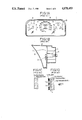
- FIG. 1A is a front view showing an example of prior-art mechanical indicating instrument for the automotive vehicle
- FIG. 1B is a diagrammatical cross-sectional view of FIG. 1A;
- FIG. 1C is a partial enlarged cross-sectional view of the front cover of the instrument shown in FIG. 1B;
- FIG. 1D is a partial enlarged cross-sectional view of the dial of the instrument shown in FIG. 1B;
- FIG. 2A is an enlarged top view showing a pointer and a pointer cover of an indicating instrument for an automotive vehicle according to the present invention
- FIG. 2B is a partial enlarged cross-sectional view of the dial of the indicating instrument shown in FIG. 2A;
- FIG. 2C is a cross-sectional view of the indicating instrument shown in FIG. 2A;
- FIG. 3A is a perspective view showing a meter and a pointer incorporated in the indicating instrument shown in FIG. 2A;
- FIG. 3B is an illustration for assistance in explaining an offset operation of the meter shown in FIG. 3A;
- FIG. 3C is a graphical representation showing two voltage signals applied to two coils of the meter shown in FIG. 3A;
- FIG. 4A is a front view showing a second embodiment of the indicating instrument of the present invention.
- FIG. 4B is a diagrammatical cross-sectional view of FIG. 4A;
- FIG. 5A is a perspective view showing a pointer and a pointer cap used for the instrument of the present invention
- FIG. 5B is an exploded view of the pointer and the pointer cap shown in FIG. 5A;
- FIG. 6A is a cross-sectional view showing a third embodiment of the indicating instrument of the present invention.
- FIG. 6B is a partial enlarged cross-sectional view of the front cover of the instrument shown in FIG. 6A.
- FIG. 6C is a partial enlarged cross-sectional view of the dial of the instrument shown in FIG. 6A.
- FIGS. 1A, 1B and 1C show a prior-art mechanical indicating instrument.
- This instrument includes a engine speed mater A, a vehicle speed meter B, a coolant temperature meter C, a fuel meter D, etc., as shown in FIG. 1A.
- this mechanical indicating instrument comprises a dial 1, pointers 2 disposed in front of the dial 1, cylindrical light guide plates 3 disposed in back of the dial 1, dial illuminating lamps 4 each for illuminating both the dial 1 and the pointer 2 along the light guide plate 3. Further, the instrument is housed within an instrument housing 6 covered by a front cover 5.
- This front cover 5 is made of a colorless, transparent synthetic resin as shown in FIG. 1C, and the dial 1 is formed by a multilayer including a transparent material 1a, a colored layer 1b, a white layer 1C and a black opaque layer 1d in which scale marks 1e such as characters, numerals, etc. are engraved, all layers being arranged from the inside of the intrument.
- the pointers and the dial are visible whenever illuminated by external light, even after the ignition switch has been turned off.
- FIGS. 2A, 2B, and 2C show a first embodiment of the indicating instrument.
- the feature of this embodiment is to cover a pointer by pointer cover whenever the ignition switch is turned off, in order to unvisualize the pointer of the mechanical indicating instrument.
- a pointer 2 fixed to a pointer shaft 2A and covered by a pointer cap 30 is disposed on a dial 1A on which numerals (0, 20, . . . ) 1a are formed.
- the numeral 10 denotes a pointer cover for covering the pointer 2 when the pointer 2 indicates an indication below zero or the meter is deactivated.
- the dial 1A is composed of a black matted opaque layer 1d in which scale marks 1e such as characters, numerals, etc. are engraved and a white light transmissible paint is applied thereto, and a semitransparent layer 1h (e.g. clear lacquer painted).
- a black matted opaque layer 1d in which scale marks 1e such as characters, numerals, etc. are engraved and a white light transmissible paint is applied thereto, and a semitransparent layer 1h (e.g. clear lacquer painted).
- an internal meter 20 of cross-sectional movement type and two rear lamps 4 are arranged in back of the dial 1A. These lamps 4 are lighted up whenever the ignition switch is turned on.
- FIG. 3A shows the cross-sectional movement type meter 20 including a first coil 20a and a second coil 20b, and a rotary permanent magnet 20c driven by a resultant magnetic field generated by the two coils 20a and 20b.
- the pointer shaft 2A is fixed at the center of the permanent magnet 20c in such a way that the longitudinal direction of the pointer 2 matches the magnetic pole arrangement direction (connecting between the two north and south poles N and S).
- the meter 20 is provided with a pointer offset permanent magnet 20d (shown in FIG. 3B) so disposed as to drive the rotary magnet 20c to a position beyond the zero point by an attractive force generated between the two magnets 20c and 20d.
- a supply voltage S va (e.g. +3 V) is applied to a first coil 20a as shown in FIG. 3c, so that a magnetomotive force H a is generated to drive the pointer 2 to a zero position (0° in pointer angle), as shown by solid lines in FIG. 3B. Therefore, the pointer 2 appears from under the pointer cover 10 and indicates its zero position.
- the first coil 20a is energized by a voltage S va which decreases as shown in FIG. 3c; on the other hand, the second coil 20b is energized by a voltage S vb which increases as shown in FIG. 3c.
- the resultant magnetomotive force grates a rotary magnetic field, so that the permanent magnet 20c is rotated, until the N-S pole direction matches the magnetic field generated by the two coils 20a and 20b, to indicate a measured value on the dial.
- the pointer 2 is rotated at 45° pointer angle.
- the magnetomotive force H a is zero and the magnetomotive force H b is the maximum, the pointer 2 is rotated at 90° pointer angle.
- the lamps 4 are always lighted up whenever the ignition switch is turned on, it is preferable to reduce the quantity of light emitted from the lamps 4 manually or automatically according to the brightness within the passenger compartment (the luminance of the lamp is preferably reduced at night).
- FIGS. 4A and 4B show a second embodiment of the indicating instrument of the present invention.
- a speed meter comprises a dial 1A, a pointer 2, an internal meter 20, a pointer cover 10, and a front cover 5A.
- Lamps 4 for illuminating the dial 1A from the rear side thereof are disposed within the housing 6.
- the front cover 5A is semitransparent.
- the feature of this second embodiment is to illuminate the pointer 2 made of a transparent material by light guided to the center of the pointer through an appropriate light guide member (not shown).
- the pointer 2 is made up of a pointer needle 2a, a needle center portion 2b, and a light guide portion 2c.
- a pointer cap 30 includes a shaft portion 30b, a cap portion 30c, a channel-shaped pointer engage portion 30d and a counterweight 30e. This pointer engage portion 30d is closely engaged with the base portion of the pointer needle 2a.
- a pointer illumination light is guided from the lamps 4 disposed in back of the dial toward the center of the pointer 2 along two wall-shaped light guide members.
- the pointer 2 is made of a red or green transparent material, even if the pointer 2 is covered by a semitransparent cover 5A, the illuminated pointer 2 is recognizable. Further, since the pointer 2 is covered by the pointer cover 10 and the pointer cap 30, when the ignition switch is turned off, it is possible to unvisualize the indicator instrument. When the ignition switch is turned on, since the pointer 2 appears from under the pointer cover 10 and the pointer and the dial are both illuminated, the driver can see the pointer and dial through the semitransparent glass cover 5A.
- FIGS. 6A, 6B and 6C show the third embodiment of the present invention.
- This instrument comprises a dial 1A, a pointer 2 disposed in front of the dial 1A, a light guide plate 3 disposed in back of the dial 1, a back illumination lamp 4 for illuminating both the dial 1A and the pointer 2 via the cylindrical light guide plate 3.
- the instrument further comprises a front illumination lamp 7 for illuminating the dial 1A and pointer 2 from the front side thereof through a throughhole 8 formed in the instrument housing 6.
- the front cover 5A is made of a colored transparent material (e.g. black) as shown in FIG. 6B
- the dial 1A is formed by a multilayer including a black opaque layer 1d in which scale marks 1e such as characters, symbols, etc. are engraved, a colored transparent material 1g and a semitransparent layer 1h (e.g. clear lacquer painted), as shown in FIG. 6C.
- the front and back illumination lamps 7 and 4 are turned on or off in linkage with the ignition switch operation. Further, the front illumination lamp 7 is operated in linkage with the vehicle light switch. That is to say, the front and back illumination lamps 7 and 4 are turned on when the ignition switch (not shown) is turned on, and off when the ignition switch is turned off. Further, the intensity of light emitted from the front lamp 7 is decreased when the light switch (not shown) is turned on in the nighttime.
- the dial 1 and the pointer 2 are not illuminated from the back and front sides thereof. Further, the dial 1 and the pointer 2 are isolated from the external natural light by the colored (e.g. black) transparent front cover 5A. Therefore, the driver cannot substantially recognize the dial 1 and the pointer 2. This is because the display characters 1e are engraved in the black layer 1d and covered with the glass-state semitransparent layer 1h (e.g. clear lacquer painted), so that the contrast between the characters or scale marks and the black layer 1d is low.
- the glass-state semitransparent layer 1h e.g. clear lacquer painted
- the characters, numerals, scale marks formed on the dial 1A can be recognized by light transmitted through the recesses or holes 1e, the colored transparent layer 1g and the semitransparent layer 1h.
- the pointer 2 is brightened by the light emitted from the lamp 4 through the cylindrical light guide 3.
- the front lamp 7 is lighted up to directly illuminate the pointer 2, the pointer 2 can be recognized more clearly.
- the displays can be recognized on the basis of light emitted from the lamp 4 through the front colored transparent cover 5A.
- a black (colored) transparent front cover 5A is disposed in front of the pointer and the dial, the light reflected from the illuminated pointer and the dial are shut off by the front cover 5A.
- the pointer can be seen through the colored transparent layer 1g, when the intensity of light emitted from the lamp 4 is increased, it is possible to visualize the pointer and the dial without use of a special lamp of high luminous energy.
- the front lamp 7 is additionally provided, it is possible to sufficiently illuminate the pointer 2. Further, since this lamp 7 directly illuminates the dial, it is preferable to select a front lamp 7 whose quantity of light is smaller than that of the back lamp 4.
Landscapes
- Engineering & Computer Science (AREA)
- Mechanical Engineering (AREA)
- Physics & Mathematics (AREA)
- General Physics & Mathematics (AREA)
- Details Of Measuring Devices (AREA)
Abstract
Description
Claims (7)
Applications Claiming Priority (4)
| Application Number | Priority Date | Filing Date | Title |
|---|---|---|---|
| JP62-037182[U] | 1987-03-16 | ||
| JP3718287U JPH0511461Y2 (en) | 1987-03-16 | 1987-03-16 | |
| JP1987174994U JPH0178918U (en) | 1987-11-18 | 1987-11-18 | |
| JP62-174994[U] | 1987-11-28 |
Publications (1)
| Publication Number | Publication Date |
|---|---|
| US4878453A true US4878453A (en) | 1989-11-07 |
Family
ID=26376283
Family Applications (1)
| Application Number | Title | Priority Date | Filing Date |
|---|---|---|---|
| US07/168,398 Expired - Lifetime US4878453A (en) | 1987-03-16 | 1988-03-15 | Indicating instrument for automotive vehicle |
Country Status (2)
| Country | Link |
|---|---|
| US (1) | US4878453A (en) |
| DE (1) | DE3808826C2 (en) |
Cited By (34)
| Publication number | Priority date | Publication date | Assignee | Title |
|---|---|---|---|---|
| US5044304A (en) * | 1988-06-08 | 1991-09-03 | Kanto Seiki Co., Ltd. | Illuminated indicator gauge |
| US5129269A (en) * | 1989-05-15 | 1992-07-14 | Darling-Delaware Company, Inc. | Meter for automobile |
| US5138968A (en) * | 1990-07-12 | 1992-08-18 | Yazaki Corporation | Cross coil-shaped indicating instrument |
| DE9301584U1 (en) * | 1993-02-05 | 1993-03-25 | Kastner, Reinhard, 8678 Schwarzenbach a Wald | Instrument sheet for measuring and display instruments |
| US5245313A (en) * | 1991-02-20 | 1993-09-14 | Atoma International, Inc. | Automatic transmission lever position indicating device |
| US5270682A (en) * | 1989-12-13 | 1993-12-14 | Yazaki Corporation | Display devices of the reflection type for vehicle |
| US5289794A (en) * | 1992-09-23 | 1994-03-01 | Delco Electronics Corporation | Magnetically aligned transmission shift indicator |
| US5291851A (en) * | 1990-06-29 | 1994-03-08 | Yazaki Corporation | Gauge for automobile |
| US5295049A (en) * | 1991-09-13 | 1994-03-15 | Stanley Electric Co., Ltd. | Instrument for vehicle |
| US5690049A (en) * | 1996-02-05 | 1997-11-25 | Ford Motor Company | Compact gauge assembly |
| US5797345A (en) * | 1996-11-13 | 1998-08-25 | Ford Global Technologies, Inc. | Illuminated pointer for instrument gage |
| US5821867A (en) * | 1995-12-08 | 1998-10-13 | Ford Motor Company | Transreflective instrument display |
| US5842435A (en) * | 1994-07-28 | 1998-12-01 | Yazaki Corporation | Index for a measuring instrument |
| US5977868A (en) * | 1998-01-17 | 1999-11-02 | Itakura; Tsuyoshi | Instrumentation for vehicle |
| US20030066349A1 (en) * | 2001-10-09 | 2003-04-10 | Toshiki Wada | Automotive meter having illuminated pointer |
| US20030121467A1 (en) * | 2001-12-27 | 2003-07-03 | Yazaki Corporation | Indicator |
| US6624608B2 (en) * | 2001-02-23 | 2003-09-23 | Denso Corporation | Indicating instrument for a vehicle |
| US6642850B1 (en) * | 1999-09-07 | 2003-11-04 | Mannesmann Vdo Ag | Indicating device |
| US20040083618A1 (en) * | 2002-10-31 | 2004-05-06 | Kelly Michael W. | High visibility taper gauge |
| US20040089219A1 (en) * | 2000-12-22 | 2004-05-13 | Alf Burau | Indicating device with a pointer and a light source |
| US20040119459A1 (en) * | 2002-09-05 | 2004-06-24 | Takashi Komura | Meter unit having magnetic pointer position detector |
| US20040189237A1 (en) * | 2003-01-30 | 2004-09-30 | Kabushiki Kaisha Toshiba | Motor controller, semiconductor integrated circuit, indicating instrument and method for controlling a motor |
| US20040239750A1 (en) * | 2001-08-29 | 2004-12-02 | Bernward Kneer | Method for the production of a dial and dial produced according to said method |
| US6827034B1 (en) * | 2002-09-25 | 2004-12-07 | Yazaki North America, Inc. | Illuminated dial and pointer display |
| DE4340709B4 (en) * | 1993-11-30 | 2006-11-23 | Siemens Ag | display |
| WO2008129924A1 (en) | 2007-04-18 | 2008-10-30 | Nippon Seiki Co., Ltd. | On-vehicle display device |
| US20100043697A1 (en) * | 2007-04-11 | 2010-02-25 | Hideki Masuda | Indicator apparatus |
| US20100186661A1 (en) * | 2009-01-27 | 2010-07-29 | Denso International America, Inc. | Hub glow pointer |
| US20100192836A1 (en) * | 2009-02-05 | 2010-08-05 | Denso Corporation | Indicating instrument for vehicle |
| US20100192835A1 (en) * | 2009-02-05 | 2010-08-05 | Denso Corporation | Indicating instrument for vehicle |
| US20100288183A1 (en) * | 2008-01-10 | 2010-11-18 | NIPPON SEIKI CO. LTD. a company | Indicating instrument |
| US20110107959A1 (en) * | 2008-04-08 | 2011-05-12 | Johnson Controls Technology Company | Indicator device and display device, particularly for a motor vehicle, and needle mounting method for a display device |
| US20110283932A1 (en) * | 2010-05-20 | 2011-11-24 | Li-Chen Chen | Alarm mark structure of a micro-differential pressure gauge |
| US20110285531A1 (en) * | 2010-05-20 | 2011-11-24 | Li-Chen Chen | Pointer- type alarm mark structure of a micro-differential pressure gauge |
Families Citing this family (10)
| Publication number | Priority date | Publication date | Assignee | Title |
|---|---|---|---|---|
| KR970009793B1 (en) * | 1991-08-19 | 1997-06-18 | 미쯔비시 지도샤 고교 가부시끼가이샤 | Car display |
| DE4137680A1 (en) * | 1991-11-15 | 1993-05-19 | Bayerische Motoren Werke Ag | Rotary magnet quotient measurement mechanism for motor vehicle engine - contains magnetic coils acted on by pulse width modulated signals dependent on physical measurement parameter |
| FR2707225B1 (en) * | 1993-07-06 | 1995-08-18 | Sagem | Standard vehicle dashboard module. |
| WO1998032624A1 (en) * | 1997-01-25 | 1998-07-30 | Kim Kyong Hee | Indicator for a car instrument panel |
| DE19728294B4 (en) * | 1997-07-03 | 2005-11-10 | Ifm Electronic Gmbh | Electric, analogue indicating instrument with pointer reset |
| FR2765534B1 (en) * | 1997-07-03 | 1999-09-24 | Magneti Marelli France | DASHBOARD FOR MOTOR VEHICLE |
| DE19757564A1 (en) | 1997-12-23 | 1999-07-01 | Mannesmann Vdo Ag | Display device |
| FR2787401B1 (en) * | 1998-12-22 | 2001-03-23 | Magneti Marelli France | IMPROVED DASHBOARD FOR MOTOR VEHICLE |
| DE19908136A1 (en) * | 1999-02-25 | 2000-08-31 | Volkswagen Ag | Method for operating a display device in a motor vehicle and a display device itself |
| DE10256170A1 (en) * | 2002-12-02 | 2004-06-17 | Siemens Ag | Display instrument and method for producing a display instrument |
Citations (33)
| Publication number | Priority date | Publication date | Assignee | Title |
|---|---|---|---|---|
| US1723390A (en) * | 1928-05-26 | 1929-08-06 | Fed Products Corp | Cover plate for measuring instruments |
| US2668945A (en) * | 1954-02-09 | Electrical measuring instrument | ||
| US2793605A (en) * | 1954-12-01 | 1957-05-28 | Gen Motors Corp | Continuous vivid arc instrument |
| US2945313A (en) * | 1958-08-29 | 1960-07-19 | George K C Hardesty | Polychromatic selective display panel |
| DE1118878B (en) * | 1960-11-23 | 1961-12-07 | Vdo Schindling | Cross-coil rotary magnet measuring device |
| FR1326538A (en) * | 1962-03-29 | 1963-05-10 | Improvements to dashboards | |
| US3094659A (en) * | 1963-06-18 | Permanent magnet rotor type electric meter | ||
| US3110882A (en) * | 1961-04-07 | 1963-11-12 | Gen Motors Corp | Laminated panel device having electroluminescent indicating areas |
| US3257748A (en) * | 1960-12-07 | 1966-06-28 | George K C Hardesty | Illumination systems with integral dimming |
| US3499417A (en) * | 1967-06-07 | 1970-03-10 | Stewart Warner Corp | Translucent instrument dial means |
| US3511211A (en) * | 1967-07-21 | 1970-05-12 | Ametek Inc | Polarized gauge dial |
| US3568630A (en) * | 1969-02-26 | 1971-03-09 | Lewis Eng Co | Illuminated indicator means and instrument |
| US3590233A (en) * | 1969-11-12 | 1971-06-29 | Lewis Eng Co | Removable and replaceable insturment lamps |
| US4004546A (en) * | 1975-05-02 | 1977-01-25 | Ametek, Inc. | Illuminated indicator gauge |
| US4090131A (en) * | 1976-07-26 | 1978-05-16 | Mas Joseph A | Moving magnet meter having a closed magnetic circuit rotor |
| US4163428A (en) * | 1977-09-09 | 1979-08-07 | Nissan Motor Company, Limited | Indicator gauge with illuminated pointer |
| US4180847A (en) * | 1978-09-01 | 1979-12-25 | The Bendix Corporation | Lighting display insensitive to extraneous light |
| US4233927A (en) * | 1978-06-21 | 1980-11-18 | Nissan Motor Company, Limited | Instrument assembly with illuminated meter mounting panel |
| US4252078A (en) * | 1978-04-05 | 1981-02-24 | Nissan Motor Company, Limited | Meter having illuminated pointer |
| US4300470A (en) * | 1978-11-10 | 1981-11-17 | Yazaki Sogyo Kabushiki Kaisha | Luminant pointer for meters |
| US4335351A (en) * | 1978-03-31 | 1982-06-15 | Faria Thomas G | Moving magnet electrical meter with single pivot pin for the moving magnet and a fixed return magnet |
| US4380043A (en) * | 1980-12-05 | 1983-04-12 | Toyota Jidosha Kogyo Kabushiki Kaisha | Apparatus for illuminating instrument pointers |
| DE3201571A1 (en) * | 1982-01-20 | 1983-07-28 | Vdo Adolf Schindling Ag, 6000 Frankfurt | Display device |
| DE3218010A1 (en) * | 1982-05-13 | 1983-11-17 | Bayerische Motoren Werke AG, 8000 München | INSTRUMENT CARRIER FOR MOTOR VEHICLES |
| US4431966A (en) * | 1981-05-12 | 1984-02-14 | Sangamo Weston, Inc. | Modular backlighted analog/digital instrument display |
| US4492920A (en) * | 1981-06-22 | 1985-01-08 | Beede Electrical Instrument Co., Inc. | Electric indicator with return-to-zero feature and compensating coil to cancel the return-to-zero feature during measurement |
| EP0133446A1 (en) * | 1983-08-10 | 1985-02-27 | VDO Adolf Schindling AG | Moving crossed coil instrument |
| US4559582A (en) * | 1984-09-04 | 1985-12-17 | Allied Corporation | Indicator illuminated with electroluminescent lighting |
| DE3437164A1 (en) * | 1984-10-10 | 1986-04-17 | Vdo Adolf Schindling Ag, 6000 Frankfurt | DISPLAY DEVICE |
| US4625262A (en) * | 1983-07-08 | 1986-11-25 | Yazaki Corporation | Pointer illuminating structure in measuring instrument |
| US4646007A (en) * | 1985-03-25 | 1987-02-24 | Faria Thomas G | Tachometer indicator with uncompensated magnetic return to zero |
| US4724601A (en) * | 1986-02-10 | 1988-02-16 | General Motors Corporation | Method of manufacturing a return-to-zero gauge |
| US4758784A (en) * | 1985-11-15 | 1988-07-19 | Stewart Warner Corporation | Air core gauge with zero pointer return related application |
Family Cites Families (1)
| Publication number | Priority date | Publication date | Assignee | Title |
|---|---|---|---|---|
| JPS5719491U (en) * | 1980-07-09 | 1982-02-01 |
-
1988
- 1988-03-15 US US07/168,398 patent/US4878453A/en not_active Expired - Lifetime
- 1988-03-16 DE DE3808826A patent/DE3808826C2/en not_active Expired - Lifetime
Patent Citations (33)
| Publication number | Priority date | Publication date | Assignee | Title |
|---|---|---|---|---|
| US3094659A (en) * | 1963-06-18 | Permanent magnet rotor type electric meter | ||
| US2668945A (en) * | 1954-02-09 | Electrical measuring instrument | ||
| US1723390A (en) * | 1928-05-26 | 1929-08-06 | Fed Products Corp | Cover plate for measuring instruments |
| US2793605A (en) * | 1954-12-01 | 1957-05-28 | Gen Motors Corp | Continuous vivid arc instrument |
| US2945313A (en) * | 1958-08-29 | 1960-07-19 | George K C Hardesty | Polychromatic selective display panel |
| DE1118878B (en) * | 1960-11-23 | 1961-12-07 | Vdo Schindling | Cross-coil rotary magnet measuring device |
| US3257748A (en) * | 1960-12-07 | 1966-06-28 | George K C Hardesty | Illumination systems with integral dimming |
| US3110882A (en) * | 1961-04-07 | 1963-11-12 | Gen Motors Corp | Laminated panel device having electroluminescent indicating areas |
| FR1326538A (en) * | 1962-03-29 | 1963-05-10 | Improvements to dashboards | |
| US3499417A (en) * | 1967-06-07 | 1970-03-10 | Stewart Warner Corp | Translucent instrument dial means |
| US3511211A (en) * | 1967-07-21 | 1970-05-12 | Ametek Inc | Polarized gauge dial |
| US3568630A (en) * | 1969-02-26 | 1971-03-09 | Lewis Eng Co | Illuminated indicator means and instrument |
| US3590233A (en) * | 1969-11-12 | 1971-06-29 | Lewis Eng Co | Removable and replaceable insturment lamps |
| US4004546A (en) * | 1975-05-02 | 1977-01-25 | Ametek, Inc. | Illuminated indicator gauge |
| US4090131A (en) * | 1976-07-26 | 1978-05-16 | Mas Joseph A | Moving magnet meter having a closed magnetic circuit rotor |
| US4163428A (en) * | 1977-09-09 | 1979-08-07 | Nissan Motor Company, Limited | Indicator gauge with illuminated pointer |
| US4335351A (en) * | 1978-03-31 | 1982-06-15 | Faria Thomas G | Moving magnet electrical meter with single pivot pin for the moving magnet and a fixed return magnet |
| US4252078A (en) * | 1978-04-05 | 1981-02-24 | Nissan Motor Company, Limited | Meter having illuminated pointer |
| US4233927A (en) * | 1978-06-21 | 1980-11-18 | Nissan Motor Company, Limited | Instrument assembly with illuminated meter mounting panel |
| US4180847A (en) * | 1978-09-01 | 1979-12-25 | The Bendix Corporation | Lighting display insensitive to extraneous light |
| US4300470A (en) * | 1978-11-10 | 1981-11-17 | Yazaki Sogyo Kabushiki Kaisha | Luminant pointer for meters |
| US4380043A (en) * | 1980-12-05 | 1983-04-12 | Toyota Jidosha Kogyo Kabushiki Kaisha | Apparatus for illuminating instrument pointers |
| US4431966A (en) * | 1981-05-12 | 1984-02-14 | Sangamo Weston, Inc. | Modular backlighted analog/digital instrument display |
| US4492920A (en) * | 1981-06-22 | 1985-01-08 | Beede Electrical Instrument Co., Inc. | Electric indicator with return-to-zero feature and compensating coil to cancel the return-to-zero feature during measurement |
| DE3201571A1 (en) * | 1982-01-20 | 1983-07-28 | Vdo Adolf Schindling Ag, 6000 Frankfurt | Display device |
| DE3218010A1 (en) * | 1982-05-13 | 1983-11-17 | Bayerische Motoren Werke AG, 8000 München | INSTRUMENT CARRIER FOR MOTOR VEHICLES |
| US4625262A (en) * | 1983-07-08 | 1986-11-25 | Yazaki Corporation | Pointer illuminating structure in measuring instrument |
| EP0133446A1 (en) * | 1983-08-10 | 1985-02-27 | VDO Adolf Schindling AG | Moving crossed coil instrument |
| US4559582A (en) * | 1984-09-04 | 1985-12-17 | Allied Corporation | Indicator illuminated with electroluminescent lighting |
| DE3437164A1 (en) * | 1984-10-10 | 1986-04-17 | Vdo Adolf Schindling Ag, 6000 Frankfurt | DISPLAY DEVICE |
| US4646007A (en) * | 1985-03-25 | 1987-02-24 | Faria Thomas G | Tachometer indicator with uncompensated magnetic return to zero |
| US4758784A (en) * | 1985-11-15 | 1988-07-19 | Stewart Warner Corporation | Air core gauge with zero pointer return related application |
| US4724601A (en) * | 1986-02-10 | 1988-02-16 | General Motors Corporation | Method of manufacturing a return-to-zero gauge |
Cited By (51)
| Publication number | Priority date | Publication date | Assignee | Title |
|---|---|---|---|---|
| US5044304A (en) * | 1988-06-08 | 1991-09-03 | Kanto Seiki Co., Ltd. | Illuminated indicator gauge |
| US5129269A (en) * | 1989-05-15 | 1992-07-14 | Darling-Delaware Company, Inc. | Meter for automobile |
| US5270682A (en) * | 1989-12-13 | 1993-12-14 | Yazaki Corporation | Display devices of the reflection type for vehicle |
| US5291851A (en) * | 1990-06-29 | 1994-03-08 | Yazaki Corporation | Gauge for automobile |
| US5138968A (en) * | 1990-07-12 | 1992-08-18 | Yazaki Corporation | Cross coil-shaped indicating instrument |
| US5398018A (en) * | 1991-02-20 | 1995-03-14 | Atoma International Inc. | Automatic transmission lever position indicating device |
| US5245313A (en) * | 1991-02-20 | 1993-09-14 | Atoma International, Inc. | Automatic transmission lever position indicating device |
| US5512875A (en) * | 1991-02-20 | 1996-04-30 | Atoma International Inc. | Automatic transmission lever position indicating device |
| US5295049A (en) * | 1991-09-13 | 1994-03-15 | Stanley Electric Co., Ltd. | Instrument for vehicle |
| US5289794A (en) * | 1992-09-23 | 1994-03-01 | Delco Electronics Corporation | Magnetically aligned transmission shift indicator |
| DE9301584U1 (en) * | 1993-02-05 | 1993-03-25 | Kastner, Reinhard, 8678 Schwarzenbach a Wald | Instrument sheet for measuring and display instruments |
| DE4340709B4 (en) * | 1993-11-30 | 2006-11-23 | Siemens Ag | display |
| US5842435A (en) * | 1994-07-28 | 1998-12-01 | Yazaki Corporation | Index for a measuring instrument |
| US5821867A (en) * | 1995-12-08 | 1998-10-13 | Ford Motor Company | Transreflective instrument display |
| US5690049A (en) * | 1996-02-05 | 1997-11-25 | Ford Motor Company | Compact gauge assembly |
| US5797345A (en) * | 1996-11-13 | 1998-08-25 | Ford Global Technologies, Inc. | Illuminated pointer for instrument gage |
| US5977868A (en) * | 1998-01-17 | 1999-11-02 | Itakura; Tsuyoshi | Instrumentation for vehicle |
| US6642850B1 (en) * | 1999-09-07 | 2003-11-04 | Mannesmann Vdo Ag | Indicating device |
| US20040089219A1 (en) * | 2000-12-22 | 2004-05-13 | Alf Burau | Indicating device with a pointer and a light source |
| US6624608B2 (en) * | 2001-02-23 | 2003-09-23 | Denso Corporation | Indicating instrument for a vehicle |
| US20040239750A1 (en) * | 2001-08-29 | 2004-12-02 | Bernward Kneer | Method for the production of a dial and dial produced according to said method |
| US20030066349A1 (en) * | 2001-10-09 | 2003-04-10 | Toshiki Wada | Automotive meter having illuminated pointer |
| US6655209B2 (en) * | 2001-10-09 | 2003-12-02 | Denso Corporation | Automotive meter having illuminated pointer |
| US20030121467A1 (en) * | 2001-12-27 | 2003-07-03 | Yazaki Corporation | Indicator |
| US6904866B2 (en) * | 2001-12-27 | 2005-06-14 | Yazaki Corporation | Indicator |
| US20040119459A1 (en) * | 2002-09-05 | 2004-06-24 | Takashi Komura | Meter unit having magnetic pointer position detector |
| US6940269B2 (en) * | 2002-09-05 | 2005-09-06 | Denso Corporation | Meter unit having magnetic pointer position detector |
| US6827034B1 (en) * | 2002-09-25 | 2004-12-07 | Yazaki North America, Inc. | Illuminated dial and pointer display |
| US20040083618A1 (en) * | 2002-10-31 | 2004-05-06 | Kelly Michael W. | High visibility taper gauge |
| US20040189237A1 (en) * | 2003-01-30 | 2004-09-30 | Kabushiki Kaisha Toshiba | Motor controller, semiconductor integrated circuit, indicating instrument and method for controlling a motor |
| US7129669B2 (en) * | 2003-01-30 | 2006-10-31 | Kabushiki Kaisha Toshiba | Motor controller, semiconductor integrated circuit, indicating instrument and method for controlling a motor |
| US8356570B2 (en) * | 2007-04-11 | 2013-01-22 | Nippon Seiki Co., Ltd. | Indicator apparatus |
| US20100043697A1 (en) * | 2007-04-11 | 2010-02-25 | Hideki Masuda | Indicator apparatus |
| US20100127958A1 (en) * | 2007-04-18 | 2010-05-27 | Hideki Masuda | On-vehicle display apparatus |
| EP2146187A4 (en) * | 2007-04-18 | 2013-06-19 | Nippon Seiki Co Ltd | VEHICLE DISPLAY DEVICE |
| US8427407B2 (en) * | 2007-04-18 | 2013-04-23 | Nippon Seiki Co., Ltd. | On-vehicle flat display apparatus |
| WO2008129924A1 (en) | 2007-04-18 | 2008-10-30 | Nippon Seiki Co., Ltd. | On-vehicle display device |
| US20100288183A1 (en) * | 2008-01-10 | 2010-11-18 | NIPPON SEIKI CO. LTD. a company | Indicating instrument |
| US8365681B2 (en) * | 2008-01-10 | 2013-02-05 | Nippon Seiki Co., Ltd. | Indicating instrument |
| US9003998B2 (en) * | 2008-04-08 | 2015-04-14 | Johnson Controls Technology Company | Indicator device and display device, particularly for a motor vehicle, and needle mounting method for a display device |
| US20110107959A1 (en) * | 2008-04-08 | 2011-05-12 | Johnson Controls Technology Company | Indicator device and display device, particularly for a motor vehicle, and needle mounting method for a display device |
| US8225736B2 (en) * | 2009-01-27 | 2012-07-24 | Denso International America, Inc. | Hub glow pointer |
| US20100186661A1 (en) * | 2009-01-27 | 2010-07-29 | Denso International America, Inc. | Hub glow pointer |
| US20100192835A1 (en) * | 2009-02-05 | 2010-08-05 | Denso Corporation | Indicating instrument for vehicle |
| US8111032B2 (en) * | 2009-02-05 | 2012-02-07 | Denso Corporation | Indicating instrument for vehicle |
| US8102139B2 (en) * | 2009-02-05 | 2012-01-24 | Denso Corporation | Indicating instrument for vehicle |
| US20100192836A1 (en) * | 2009-02-05 | 2010-08-05 | Denso Corporation | Indicating instrument for vehicle |
| US20110285531A1 (en) * | 2010-05-20 | 2011-11-24 | Li-Chen Chen | Pointer- type alarm mark structure of a micro-differential pressure gauge |
| US20110283932A1 (en) * | 2010-05-20 | 2011-11-24 | Li-Chen Chen | Alarm mark structure of a micro-differential pressure gauge |
| US8651043B2 (en) * | 2010-05-20 | 2014-02-18 | Hwa Chi Technology Co., Ltd. | Alarm mark structure of a micro-differential pressure gauge |
| US8714100B2 (en) * | 2010-05-20 | 2014-05-06 | Hwa Chi Technology Co., Ltd. | Pointer-type alarm mark structure of a micro-differential pressure gauge |
Also Published As
| Publication number | Publication date |
|---|---|
| DE3808826A1 (en) | 1988-10-06 |
| DE3808826C2 (en) | 1993-11-04 |
Similar Documents
| Publication | Publication Date | Title |
|---|---|---|
| US4878453A (en) | Indicating instrument for automotive vehicle | |
| EP1258712B1 (en) | Meter for vehicle | |
| US5546888A (en) | Surface mounted gauge with illuminated pointer | |
| US4875433A (en) | Illumination meter dial device | |
| EP0345727B1 (en) | Illuminated indicator gauge | |
| JP2010266409A (en) | Vehicle display device | |
| US10260917B2 (en) | Structure of scale graduation and vehicle instrument | |
| US10195942B2 (en) | Display device | |
| US20090116212A1 (en) | Indicator Having an Electrooptical Display | |
| JP2003215142A (en) | Vehicle instrument | |
| EP0367953B1 (en) | Automotive meter with illuminator | |
| JP3812540B2 (en) | Vehicle instrument | |
| JP2006118892A (en) | Pointer instrument | |
| JP2003344118A (en) | Illuminating device | |
| JP2002357463A (en) | Luminescent hands for instruments and instruments | |
| JP4737494B2 (en) | Instrument device | |
| JP2003202247A (en) | Pointer instrument | |
| JPH11281409A (en) | Instrument apparatus | |
| JP4933069B2 (en) | Vehicle indicator instrument | |
| JP2007187576A (en) | Vehicle indicator instrument | |
| JP2003344119A (en) | Meter unit | |
| JPH09237050A (en) | Liquid crystal display lighting device | |
| JPH0557622U (en) | Pointer lighting device | |
| KR0132764Y1 (en) | Apparatus for illuminating a pointer of meter cluster in a car | |
| JP2959512B2 (en) | Instrument lighting device |
Legal Events
| Date | Code | Title | Description |
|---|---|---|---|
| AS | Assignment |
Owner name: YAZAKI CORPORATION, 4-28, MITA 1-CHOME, MINATO-KU, Free format text: ASSIGNMENT OF ASSIGNORS INTEREST.;ASSIGNORS:INOUE, TAI;SUGITA, MASAYA;OKAMOTO, KEIJI;REEL/FRAME:004889/0448 Effective date: 19880428 Owner name: YAZAKI CORPORATION, JAPAN Free format text: ASSIGNMENT OF ASSIGNORS INTEREST;ASSIGNORS:INOUE, TAI;SUGITA, MASAYA;OKAMOTO, KEIJI;REEL/FRAME:004889/0448 Effective date: 19880428 |
|
| STCF | Information on status: patent grant |
Free format text: PATENTED CASE |
|
| FEPP | Fee payment procedure |
Free format text: PAYOR NUMBER ASSIGNED (ORIGINAL EVENT CODE: ASPN); ENTITY STATUS OF PATENT OWNER: LARGE ENTITY |
|
| FPAY | Fee payment |
Year of fee payment: 4 |
|
| FPAY | Fee payment |
Year of fee payment: 8 |
|
| FPAY | Fee payment |
Year of fee payment: 12 |