US4878024A - Magnetic resonance apparatus comprising a low-noise gradient coil - Google Patents
Magnetic resonance apparatus comprising a low-noise gradient coil Download PDFInfo
- Publication number
- US4878024A US4878024A US07/233,307 US23330788A US4878024A US 4878024 A US4878024 A US 4878024A US 23330788 A US23330788 A US 23330788A US 4878024 A US4878024 A US 4878024A
- Authority
- US
- United States
- Prior art keywords
- coil system
- conductors
- arc
- gradient coil
- arc conductors
- Prior art date
- Legal status (The legal status is an assumption and is not a legal conclusion. Google has not performed a legal analysis and makes no representation as to the accuracy of the status listed.)
- Expired - Fee Related
Links
Images


Classifications
-
- G—PHYSICS
- G01—MEASURING; TESTING
- G01R—MEASURING ELECTRIC VARIABLES; MEASURING MAGNETIC VARIABLES
- G01R33/00—Arrangements or instruments for measuring magnetic variables
- G01R33/20—Arrangements or instruments for measuring magnetic variables involving magnetic resonance
- G01R33/28—Details of apparatus provided for in groups G01R33/44 - G01R33/64
- G01R33/38—Systems for generation, homogenisation or stabilisation of the main or gradient magnetic field
- G01R33/385—Systems for generation, homogenisation or stabilisation of the main or gradient magnetic field using gradient magnetic field coils
- G01R33/3854—Systems for generation, homogenisation or stabilisation of the main or gradient magnetic field using gradient magnetic field coils means for active and/or passive vibration damping or acoustical noise suppression in gradient magnet coil systems
Definitions
- the invention relates to a gradient coil system for a magnetic resonance apparatus, comprising coils for generating mutually perpendicularly directed gradient fields, and also relates to a magnetic resonance apparatus comprising such a coil system.
- a coil system of this kind is known from EP-A-152588.
- a gradient coil system described therein comprises coils which are pairwise arranged with respect to a symmetry plane of the cylindrical measuring space.
- a steady magnetic field which is directed along an axial axis, the Z-axis, can be generated.
- coil stacks of a coil pair comprise saddle-shaped coils which are arranged diametrically with respect to one another, viewed azimuthally, and two ring-shaped coil pairs for generating a Z-gradient.
- the saddle coil stack is combined with the ring-shaped Z-gradient coils in order to form one coil stack by glueing at the area of local mutual overlaps of the coil conductors.
- Sub-coil systems thus formed can be interconnected by way of axially extending supporting elements, thus forming a complete gradient coil system which is mounted around a coil former by means of insulating, elastic intermediate pieces. This construction aims to reduce the transfer of vibrations from the gradient coils to the coil former, thus reducing the noise in the magnetic resonance apparatus.
- a coil system of the kind set forth in accordance with the invention is characterized in that, in conjunction with insulating intermediate rings, coil arcs form rigidly interconnected, ring-shaped stacks which are combined, using interconnections, so as to form a self-supporting coil system.
- fully self-supporting ring systems can be formed with current-carrying arc conductors which are rigidly clamped between the intermediate rings.
- the use of the known coil former for the gradient coil system can thus be omitted.
- Relevant arc conductors are conductively connected to one another and to a current source by means of axially extending current conductors.
- gradient coils for an Xgradient field and gradient coils for a Y-gradient field are accommodated together in one ring stack; this benefits the positioning of the coils with respect to one another and hence the exactness of the gradient fields to be generated.
- the height/width ratio of the arc conductors is comparatively high, so that the rigidity of each of the elements is increased.
- the height of the arc conductors amounts to approximately 40 mm and the width amount to 5 mm.
- the ring-shaped arc conductors are notably made of a material which is suitably electrically conductive and has a comparatively high modulus of elasticity, for example copper.
- a comparatively high height/width ratio for ring-shaped arc conductors benefits the rigidity of the coil stacks.
- the arc conductors are radially stacked instead of axially.
- An extremely rigid stack can thus be obtained.
- the arc conductors then preferably consist of cylindrical ring portions having an axial dimension of, for example 50 mm and a radial dimension of, for example 1 mm.
- a preferred embodiment of a gradient coil system comprises, for example, from six to ten coil stacks which all have substantially the same inner diameter and which are symmetrically arranged with respect to the central plane of a cylindrical measuring space.
- the generated surface between the stacks and the connection pieces at least equals the total generated surface of the stacks combined.
- An open construction of this kind can also be realized by means of said radially stacked cylindrical ring portions. Even though each of these portions per se covers a larger surface, the total generated surface need not be increased thereby.
- Coil stacks having different internal diameters offer an improvement as regards the accessibility of a patient, or enable the use of a smaller diameter for more centrally located stacks, thus reducing the amount of power supply energy required.
- a further preferred embodiment utilizes gradient coils having a mutually different arc length. In the same measuring space a more uniform gradient field can thus be realized by means of a smaller coil volume.
- ring-shaped, or band-shaped arc conductors are complemented so as to form at least substantially closed rings.
- This can be realized by means of complementary insulator rings which are preferably made of a material having mechanical properties, such as thermal expansion, elasticity modulus etc., which correspond to those of the material of the arc conductors themselves.
- the arc conductors can also be formed by electrically interrupted closed rings on which electrical contacts for interconnection conductors are provided at the area of the azimuthal boundary of the arcs. These contacts are notably constructed as sliding contacts, so that the gradient fields to be generated can be tuned as if it were.
- the intermediate pieces have a larger or smaller diameter at one radial side, so that the arc conductors are electrically shielded at the relevant side, for example from the axial conductors.
- recesses can also be provided in the insulating intermediate rings.
- intermediate pieces, and possibly also arc conductors are provided with recesses and projections for selected radial and/or azimuthal mutual positioning.
- conductor stacks are rigidly connected to a supporting cylinder having a diameter which deviates from the diameter of the stacks, its diameter preferably being larger.
- the conductors form, for example ridges on an inner surface of a supporting cylinder. Because the energy generated is proportional to the fifth power of the radius of the conductor arc, a smaller radius results in a substantial efficiency improvement because of the mounting on the inner side of the supporting cylinder. Because the supporting cylinder is now situated outside the conductors, it can be constructed to be thicker and hence more rugged, but notably also so that the suppression of noise is better.
- FIG. 1 shows a magnetic rsonance apparatus comprising a coil system in accordance with the invention
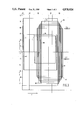
- FIG. 2 is an axial sectional view of a preferred embodiment of a coil system for such an apparatus
- FIG. 3 shows a lay-out of the arc conductors for this coil system
- FIG. 4 shows various shapes of arc conductors to be axially stacked for such a coil system
- FIG. 5 shows an embodiment of a radially stacked coil for such a coil system.
- a magnetic resonance apparatus as shown in FIG. 1 comprises a magnet system 2 for generating a steady, uniform magnetic field, a magnet system 4 for generating magnetic gradient fields, and power supply sources 6 and 8 for the magnet system 2 and the magnet system 4, respectively.
- a magnet coil 10 serves to generate an RF magnetic alternating field and is connected to cable 11 providing a source of RF output from an RF amplifier 12.
- a surface coil 13 For the detection of magnetic resonance signals generated by the RF transmitted field in an object to be examined there is included a surface coil 13.
- the coil 13 is connected to a signal amplifier 14.
- the signal amplifier 14 is connected to a phase sensitive rectifier 16 which is connected to a central control device 18.
- the central control device 18 controls a modulator 20 for feeding the RF amplifier 12, and also controls the power supply source 8 for the gradient coils, and a monitor 22 for display.
- An RF oscillator 24 controls the modulator 20 as well as the phase sensitive rectifier 16 which processes the measuring signals.
- a cooling device 26 comprising cooling ducts 27 is provided for cooling purposes, if desired.
- a cooling device of this kind can be constructed as a water cooling system for resistance coils or as a liquid helium system or nitrogen dewar system for cooled superconducting coils.
- the transmitter coil 10 which is arranged within the magnet systems 2 and 4 encloses a measuring space 28 which offers adequate space for accommodating patients in the case of an apparatus for medical diagnostic measurements. Thus, there can be generated within the measuring space 28 a steady magnetic field, gradient fields for position selection of slices to be imaged and a spatially uniform RF alternating field.
- the steady magnetic field generated by the steady magnet system therefore, is directed along the Z-axis.
- a gradient magnet system in a magnetic resonance apparatus usually comprises a coil system for each of the coordinate directions, activation of said coil systems enabling the generating of gradient fields in each of said directions and also the point-wise imaging of an object.
- the coil systems for the X-gradient and the Y-gradient in a gradient coil system in accordance with the invention are also substantially identical, but rotated through 90° with respect to one another, viewed azimuthally.
- the difference may be imposed by the construction of the entire coil system; for example, in the case of radial stacking the radius may deviate slightly and in the case of axial stacking the Z location may deviate slightly.
- a first coil stack 42 for X-Y gradient fields is situated in the symmetry plane and comprises, for example four arc conductors, two of which serve for an X-gradient field and two for a Y-gradient field.
- a next stack pair 44 in this case comprises only one or more Z-gradient arc conductors
- a next stack pair 46 comprises, for example stacks with seven X gradient arc conductors and seven Y-gradient arc conductors
- a next stack pair 48 comprises only Z-gradient arc conductors again
- a stack pair 50 comprises, for example nine arc conductors which act as return conductors for said X and nine arc conductors which act as return conductors for said Y gradient arc conductors.
- the arc conductors for the X and Y fields need not necessarily extend through mutually the same arc angles.
- the stacks 42-50 are rigidly interconnected by means of axial connection rods 52, thus forming a rugged, self-supporting gradient coil system which is comparatively open, viewed in a generated surface 54, about the Z-axis where it covers, for example at the most from one fifth to one half of the surface area.
- arc conductors for axially stacked stacks are preferably constructed so as to be comparatively high, the height being understood to mean herein the difference in the radial dimension between the inner side and the outer side. The width, being the axially measured dimension, may then be comparatively small.
- FIG. 2 diagrammatically illustrates the lay-out of arc conductors 64 in the various stacks, wherein the arc conductors are illustrated as comparatively heavy vertical lines.
- quadrant 60 for X-Z conductors and a quadrant 62 for Y-Z conductors, which quadrants, however, do not form
- the horizontal axis coincides with the Z-axis and the vertical axis extending perpendicularly thereto represents the angle ⁇ from 0° to 90°, as indicated in FIG. 2.
- arc conductors of the stacks 42 to 50 are shown, the Z-gradient field stacks 44 and 48 being continuous rings, each of which can comprise more or less conductors (not separately shown).
- the arc conductors of the stacks 42 and 46 are connected to return arc conductors of the stack 50 by means comprising axially directed conductors 55 which are not subject to high Lorentz forces and which do not contribute to the formation of the gradient fields, so that they need not have an adapted construction or orientation.
- these conductors can be connected to the arc conductors via electrical connections which are possibly constructed as sliding contacts.
- the positioning of the necessary axial connections can be adapted, if necessary, to the location of at least a part of these axial conductors.
- FIG. 4 shows some shapes of arc conductors for axial stacking in accordance with the invention.
- An arc conductor 70 of an X or Y gradient coil extends through an angle ⁇ of, for example less than 90°; for example, see the arc conductor 70 in FIG. 3.
- Remaining portions 72 of the ring can be filled, if necessary, with an insulating material or the conductor can cover the entire ring, electrical contacts 74 then determining the arc length. Therefore, for these arc conductors interleaving need not be used.
- An arc conductor 76 extends through an angle ⁇ of, for example 160° with complementary spaces or filling pieces 78. Interlining then occurs upon stacking.
- a ring-shaped element 80 can actually represent a Z-gradient ring as well as an intermediate ring of an insulating material.
- electrical contacts 74 are again provided and the cross-section of the ring can be locally adapted to relevant requirements.
- a cross-section 82 is shown which is adapted, as far as the height is concerned, to the height of a crosssection 84 of an arc conductor and which is constructed to be comparatively thin in order to save space.
- An intermediate ring can be provided with an extension 88 or 90 on one side in order to ensure suitable shielding from the arc conductors at that side.
- an intermediate ring can be provided with extensions 88 and 90 on both sides, which extensions may comprise axially projecting edges 92 and 94, respectively, which enclose the arc conductors.
- These extensions can be provided with recesses 96 for the positioning of the axial conductors.
- the arc conductors as well as the intermediate rings can be provided with recesses or projections ensuring exact axial, radial and azimuthal positioning.
- FIG. 5 is a sectional view of an embodiment of a radially stacked stack 100, comprising arc conductors 102 which are shaped as a metal foil bent about a Z axis for example, on an insulating cylindrical substrate 106.
- arc conductors and the radially intermediate rings 104 used for stacking which intermediate rings are more cylindrical, are made of a magnetic material, arcs which are in this case situated further inwards wil not disturb the field of arcs which are situated further outwards and a suitably defined gradient field can be generated in the measuring space.
- the advantage of this form of stacking consists in that the arc conductors form strips of metal foil which can be readily cut from a plate withless loss of material and which can be bent so as to obtain the desired radius of curvature.
- the conductors or the insulators of the stack can also be readily pictured in order to provide the necessary electrical conductors, without the field being disturbed.
- Adaptation to the height of stacks comprising a different number of conductors can be realized, if desired, by means of an insulating material.
Landscapes
- Physics & Mathematics (AREA)
- Condensed Matter Physics & Semiconductors (AREA)
- General Physics & Mathematics (AREA)
- Magnetic Resonance Imaging Apparatus (AREA)
Applications Claiming Priority (2)
| Application Number | Priority Date | Filing Date | Title |
|---|---|---|---|
| NL8701947 | 1987-08-19 | ||
| NL8701947A NL8701947A (nl) | 1987-08-19 | 1987-08-19 | Magnetisch resonantie apparaat met geluidsarme gradientspoel. |
Publications (1)
| Publication Number | Publication Date |
|---|---|
| US4878024A true US4878024A (en) | 1989-10-31 |
Family
ID=19850472
Family Applications (1)
| Application Number | Title | Priority Date | Filing Date |
|---|---|---|---|
| US07/233,307 Expired - Fee Related US4878024A (en) | 1987-08-19 | 1988-08-17 | Magnetic resonance apparatus comprising a low-noise gradient coil |
Country Status (5)
| Country | Link |
|---|---|
| US (1) | US4878024A (de) |
| EP (1) | EP0304127B1 (de) |
| JP (1) | JPS6470032A (de) |
| DE (1) | DE3881982T2 (de) |
| NL (1) | NL8701947A (de) |
Cited By (8)
| Publication number | Priority date | Publication date | Assignee | Title |
|---|---|---|---|---|
| US5012191A (en) * | 1988-11-28 | 1991-04-30 | Siemens Aktiengesellschaft | Gradient coil system for a nuclear magnetic resonance tomography apparatus |
| US5256970A (en) * | 1990-11-27 | 1993-10-26 | U.S. Philips Corporation | Magnetic resonance apparatus |
| US5631618A (en) * | 1994-09-30 | 1997-05-20 | Massachusetts Institute Of Technology | Magnetic arrays |
| US5701075A (en) * | 1996-01-04 | 1997-12-23 | General Electric Company | Magnetic resonance imaging shimming by superconducting gradient shield |
| US5764059A (en) * | 1993-06-02 | 1998-06-09 | British Technology Group Limited | Acoustic screen |
| US6522144B2 (en) * | 2000-12-22 | 2003-02-18 | Ge Medical Systems Global Technology Company, Llc | RF shielding method and apparatus for an open MRI system |
| US6667619B2 (en) * | 2001-04-03 | 2003-12-23 | Bruker Biospin Gmbh | Magnetic resonance apparatus with damping of inner mechanical vibrations |
| US20130106420A1 (en) * | 2010-05-20 | 2013-05-02 | Koninklijke Philips Electronics N.V. | Magnetic resonance imaging gradient coil, magnet assembly, and system |
Families Citing this family (6)
| Publication number | Priority date | Publication date | Assignee | Title |
|---|---|---|---|---|
| FR2646920B1 (fr) * | 1989-05-12 | 1991-07-05 | Commissariat Energie Atomique | Dispositif pour la production de champs magnetiques possedant une composante a gradient constant |
| DE4029477C2 (de) * | 1989-09-29 | 1994-06-01 | Siemens Ag | Tesserale Gradientenspule für Kernspin-Tomographiegeräte |
| EP0431216A1 (de) * | 1989-12-06 | 1991-06-12 | Koninklijke Philips Electronics N.V. | Verfahren zur Verminderung des akustischen Geräusches bei magnetischen Resonanzapparaten |
| US5235283A (en) * | 1991-02-07 | 1993-08-10 | Siemens Aktiengesellschaft | Gradient coil system for a nuclear magnetic resonance tomography apparatus which reduces acoustic noise |
| DE4141514C2 (de) * | 1991-02-07 | 1997-04-10 | Siemens Ag | Gradientenspulensystem für ein Kernspin-Tomographiegerät |
| JP2982392B2 (ja) * | 1991-07-10 | 1999-11-22 | 株式会社日立製作所 | 磁気共鳴イメージング装置 |
Citations (3)
| Publication number | Priority date | Publication date | Assignee | Title |
|---|---|---|---|---|
| US4595900A (en) * | 1983-11-13 | 1986-06-17 | Elscint Ltd. | Gradient field coils for NMR imaging |
| GB2170957A (en) * | 1985-01-15 | 1986-08-13 | Oxford Magnet Tech | Coil assembly for NMR imaging |
| EP0152588B1 (de) * | 1984-02-20 | 1987-10-07 | Siemens Aktiengesellschaft | Gradientenspulen-System für eine Anlage zur kernspintomographie |
Family Cites Families (6)
| Publication number | Priority date | Publication date | Assignee | Title |
|---|---|---|---|---|
| JPS59216045A (ja) * | 1983-05-23 | 1984-12-06 | Hitachi Ltd | 傾斜磁場コイル |
| NL8303534A (nl) * | 1983-10-14 | 1985-05-01 | Philips Nv | Kernspinresonantie apparaat. |
| GB8332505D0 (en) * | 1983-12-06 | 1984-01-11 | Oxford Magnet Tech | Imaging using resonance of nuclei |
| JPS61278741A (ja) * | 1985-06-04 | 1986-12-09 | Mitsubishi Electric Corp | 核磁気共鳴画像診断装置用傾斜磁場コイル |
| DE3677344D1 (de) * | 1985-06-04 | 1991-03-07 | Mitsubishi Electric Corp | Spule fuer diagnostikgeraet zur bilderzeugung mittels magnetischer kernresonanz. |
| JPS62117541A (ja) * | 1985-11-18 | 1987-05-29 | 株式会社東芝 | 磁気共鳴イメ−ジング装置 |
-
1987
- 1987-08-19 NL NL8701947A patent/NL8701947A/nl not_active Application Discontinuation
-
1988
- 1988-08-16 DE DE88201741T patent/DE3881982T2/de not_active Expired - Fee Related
- 1988-08-16 EP EP88201741A patent/EP0304127B1/de not_active Expired - Lifetime
- 1988-08-17 US US07/233,307 patent/US4878024A/en not_active Expired - Fee Related
- 1988-08-19 JP JP63204847A patent/JPS6470032A/ja active Pending
Patent Citations (3)
| Publication number | Priority date | Publication date | Assignee | Title |
|---|---|---|---|---|
| US4595900A (en) * | 1983-11-13 | 1986-06-17 | Elscint Ltd. | Gradient field coils for NMR imaging |
| EP0152588B1 (de) * | 1984-02-20 | 1987-10-07 | Siemens Aktiengesellschaft | Gradientenspulen-System für eine Anlage zur kernspintomographie |
| GB2170957A (en) * | 1985-01-15 | 1986-08-13 | Oxford Magnet Tech | Coil assembly for NMR imaging |
Cited By (10)
| Publication number | Priority date | Publication date | Assignee | Title |
|---|---|---|---|---|
| US5012191A (en) * | 1988-11-28 | 1991-04-30 | Siemens Aktiengesellschaft | Gradient coil system for a nuclear magnetic resonance tomography apparatus |
| US5088185A (en) * | 1988-11-28 | 1992-02-18 | Siemens Aktiengesellschaft | Method for manufacturing gradient coil system for a nuclear magnetic resonance tomography apparatus |
| US5256970A (en) * | 1990-11-27 | 1993-10-26 | U.S. Philips Corporation | Magnetic resonance apparatus |
| US5764059A (en) * | 1993-06-02 | 1998-06-09 | British Technology Group Limited | Acoustic screen |
| US5631618A (en) * | 1994-09-30 | 1997-05-20 | Massachusetts Institute Of Technology | Magnetic arrays |
| US5701075A (en) * | 1996-01-04 | 1997-12-23 | General Electric Company | Magnetic resonance imaging shimming by superconducting gradient shield |
| US6522144B2 (en) * | 2000-12-22 | 2003-02-18 | Ge Medical Systems Global Technology Company, Llc | RF shielding method and apparatus for an open MRI system |
| US6667619B2 (en) * | 2001-04-03 | 2003-12-23 | Bruker Biospin Gmbh | Magnetic resonance apparatus with damping of inner mechanical vibrations |
| US20130106420A1 (en) * | 2010-05-20 | 2013-05-02 | Koninklijke Philips Electronics N.V. | Magnetic resonance imaging gradient coil, magnet assembly, and system |
| US9274192B2 (en) * | 2010-05-20 | 2016-03-01 | Koninklijke Philips N.V. | Magnetic resonance imaging gradient coil, magnet assembly, and system |
Also Published As
| Publication number | Publication date |
|---|---|
| EP0304127B1 (de) | 1993-06-23 |
| DE3881982D1 (de) | 1993-07-29 |
| JPS6470032A (en) | 1989-03-15 |
| EP0304127A1 (de) | 1989-02-22 |
| DE3881982T2 (de) | 1994-01-05 |
| NL8701947A (nl) | 1989-03-16 |
Similar Documents
| Publication | Publication Date | Title |
|---|---|---|
| US4878024A (en) | Magnetic resonance apparatus comprising a low-noise gradient coil | |
| EP0304126B1 (de) | Magnetisches Resonanzgerät mit Gradientenspulensystem | |
| EP0629875B1 (de) | Gradientenspule für magnetische Resonanz und Hochfrequenz-Abschirmung | |
| US4737718A (en) | Magnetic resonance imaging apparatus including a bird-cage r.f. coil | |
| US4616181A (en) | Nuclear magnetic resonance tomography apparatus | |
| US5168211A (en) | Magnet system | |
| US4816765A (en) | Magnetic resonance imaging apparatus comprising a quadrature coil system | |
| US4758813A (en) | Cylindrical NMR bias magnet apparatus employing permanent magnets and methods therefor | |
| US5428292A (en) | Pancake MRI magnet with modified imaging volume | |
| US4771243A (en) | Magnetic resonance imaging apparatus including field-homogenizing magnetic elements | |
| JP2584005B2 (ja) | 磁場勾配コイル装置およびそれを用いる磁気共鳴イメージングシステム | |
| EP0251342A2 (de) | Magnetanordnung | |
| EP0826977B1 (de) | Kompakter supraleitender MRI-Magnet | |
| US5574417A (en) | Open MRI magnet with homogeneous imaging volume | |
| US7282916B2 (en) | Time-variable magnetic fields generator and magnetic resonance apparatus embodying same | |
| JPH08238230A (ja) | 磁気共鳴装置および方法 | |
| EP0274149A1 (de) | Gradientenspulen-Anordnung für einen Apparat zur Bilderzeugung mittels magnetischer Resonanz | |
| EP0307981A1 (de) | Magnetisches Resonanzgerät mit integrierten HF-Gradientenspulen | |
| JP3702498B2 (ja) | 磁気共鳴撮像装置用の傾斜コイル機構 | |
| EP0173363A1 (de) | Magnetische Resonanzapparatur mit einer Sende-/Empfangsspule für hohe Frequenzen | |
| EP0620922A1 (de) | Lokale spule für einen transversalen gradienten | |
| US6982553B2 (en) | Radio frequency coil with two parallel end conductors | |
| JPH0728857B2 (ja) | 核磁気共鳴を用いた検査装置 | |
| JP2005512646A (ja) | 傾斜磁場コイル配置構造 | |
| US5689188A (en) | Magnetic resonance apparatus |
Legal Events
| Date | Code | Title | Description |
|---|---|---|---|
| AS | Assignment |
Owner name: U.S. PHILIPS CORPORATION, NEW YORK Free format text: ASSIGNMENT OF ASSIGNORS INTEREST.;ASSIGNORS:OVERWEG, JOHANNES A.;HAM, CORNELIS L. G.;REEL/FRAME:005027/0382 Effective date: 19890113 |
|
| FEPP | Fee payment procedure |
Free format text: PAYOR NUMBER ASSIGNED (ORIGINAL EVENT CODE: ASPN); ENTITY STATUS OF PATENT OWNER: LARGE ENTITY |
|
| FPAY | Fee payment |
Year of fee payment: 4 |
|
| REMI | Maintenance fee reminder mailed | ||
| LAPS | Lapse for failure to pay maintenance fees | ||
| FP | Lapsed due to failure to pay maintenance fee |
Effective date: 19971105 |
|
| STCH | Information on status: patent discontinuation |
Free format text: PATENT EXPIRED DUE TO NONPAYMENT OF MAINTENANCE FEES UNDER 37 CFR 1.362 |