US487598A - Vehicle-spring - Google Patents
Vehicle-spring Download PDFInfo
- Publication number
- US487598A US487598A US487598DA US487598A US 487598 A US487598 A US 487598A US 487598D A US487598D A US 487598DA US 487598 A US487598 A US 487598A
- Authority
- US
- United States
- Prior art keywords
- spring
- leaves
- vehicle
- section
- view
- Prior art date
- Legal status (The legal status is an assumption and is not a legal conclusion. Google has not performed a legal analysis and makes no representation as to the accuracy of the status listed.)
- Expired - Lifetime
Links
- 238000010276 construction Methods 0.000 description 7
- 150000001875 compounds Chemical class 0.000 description 2
- 210000005069 ears Anatomy 0.000 description 2
- 230000000994 depressogenic effect Effects 0.000 description 1
- 238000010408 sweeping Methods 0.000 description 1
Images

Classifications
-
- B—PERFORMING OPERATIONS; TRANSPORTING
- B60—VEHICLES IN GENERAL
- B60G—VEHICLE SUSPENSION ARRANGEMENTS
- B60G11/00—Resilient suspensions characterised by arrangement, location or kind of springs
- B60G11/02—Resilient suspensions characterised by arrangement, location or kind of springs having leaf springs only
Definitions
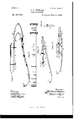
- Fig. i is an inverted view of Fig. 3.
- Fig. 5 shows the inner and outer parts single-jointed, the upper leaf of the inner section sweeping and diverging from the upper section, while its companion leaf remains adjacent, or nearly so, its length to the lower outer section. This construction is best adapted for attachment to axle orhead-block.
- Fig. 6 is merely a reversal of Fig. 5.
- Fig. 7 shows the jointure of the inner section reversed-as, for instance, to that of Fig.
- Fig. Si an enlarged side view and represents a spring constructed substantially as in Fig. I, only that the connecting-leaves of the inner sectionl diverge from the inner portion of the outer section and are not contiguous, as in the first figure.
- Fig. 9 is a top view of Fig. 8.
- Fig. l0 is a side view showing a construction substantially similar to Fig. 1,'only that the leaves of the inner connected section are perfectly straight and in that position lie Serial No. 357,589. (No model.)
- Fig. Il is an end view of Fig. l0.
- Fig. 12 is a side view'of a spring similar to that shown in Fig. l0, only that it shows the position the parts assume when weight is applied.
- the number of leaves to a spring depends somewhat upon the weight which it is designed to carry. If the weight be light, the number of leaves is less, if the weight be great the number of leaves will be more to the spring. The proportion is left to the discretion and judgment of the constructer.
- the letter A indicates the upper leaf, which is attached by bolts or clips to the vehiclebed, body-plate, spring-bar, or spring plate, Y
- the leaf A may be provided with eyed lugs or ears, as seen-in the various figures.
- the outer leaf C of the lower section is provided with a barrel, which, as before stated, fits between the eyed lugs of plate A, the connection being firmly eifected by means of a bolt and nut, as shown, or rivets may be employed for this purpose, if desired.
- D is the inner plate compoisng the upper part of the inner section of my spring.
- E is the lower inner plate of the lower section.
- the front of the spring which is designated by S, is attached to the bolster and the rear to the under side of the body, having an intermediate spring between the two side ones, which is attached below the axle, and so on, according to the construction.
- a compound vehicle-spring formed of two outer curved leaves, leaves hinged at one end to acommon axial center, and an inner spring formed of two leaves, each secured at one end within and to the outer leaves and hinged at the other end to a common axial center, both Sets of springs being in coincident vertical planes, the outer leaves turning upon their common axial center and fulcruming over the said axial center of the inner leaves, substan tially as specified.
- a compound vehicle-spring formed of two outer leaves hinged at their spring ends to a common center, one end of said springs adapted to be rigidly attached to a vehicle, the opposite end adapted to be hinged to a vehicle, in combination with the inner spring formed of two leaves attached in coincident vertical planes with the outer springs at one end and the other ends being hinged to a common axial center, which serves as a fulcrum for both the inner and outer springs, substantially as specified.
Landscapes
- Engineering & Computer Science (AREA)
- Mechanical Engineering (AREA)
- Springs (AREA)
Description
2 Sheets-Sheet 1.
(No Model.)
.0. A. BEHLEN.
.VEHICLE 's PRlNG. l
Patented Deo. 6, 1892.v
J @JJ (No Model.) 2 Sheets-Sheet 2.;
C. A. BEHLEN.
VEHICLE SPRING.
No. 487,598. Patented Deo. 6, 1892.
aww/nto@ I @Wl fw UNITED STATES PATENT Ormes.
CHARLES A. BEHLEN, OF CINCINNATI, CHIC.
VEHICLE-SPRING.v
SPECIFICATION forming part of Letters Patent No. 487,598, dated December 6, 1892.
Application filed July 2, 1890.
strength and durability, thus guardingagainst accidents from breakage and the resulting trouble and expense.
The feature of my improvement and its advantages as a whole will be understood from the description herein given and by reference to the accompanying drawings, forming part of my application, in which- Figure l is a side view of my spring. Fig. 2 is a perspective view of same; Fig. 3, a
. modified form of the abovein that the leaves forming the inner joint diverge from the outer section, the latter in turn at its jointure being provided with a curved sweep instead of being knuckle-jointed directly or in a line with one another. Fig. iis an inverted view of Fig. 3. Fig. 5 shows the inner and outer parts single-jointed, the upper leaf of the inner section sweeping and diverging from the upper section, while its companion leaf remains adjacent, or nearly so, its length to the lower outer section. This construction is best adapted for attachment to axle orhead-block. Fig. 6 is merely a reversal of Fig. 5. Fig. 7 shows the jointure of the inner section reversed-as, for instance, to that of Fig. 3- viz., instead of being joined in the same direction as the outer end it is the opposite. Fig. Sis an enlarged side view and represents a spring constructed substantially as in Fig. I, only that the connecting-leaves of the inner sectionl diverge from the inner portion of the outer section and are not contiguous, as in the first figure. Fig. 9 is a top view of Fig. 8. Fig. l0 is a side view showing a construction substantially similar to Fig. 1,'only that the leaves of the inner connected section are perfectly straight and in that position lie Serial No. 357,589. (No model.)
contiguous to the other abutting positions. This View (as indeed do all the other Views) represents the spring in its normal or unloaded condition. Fig. Il is an end view of Fig. l0. Fig. 12 is a side view'of a spring similar to that shown in Fig. l0, only that it shows the position the parts assume when weight is applied.
It may be here stated that the number of leaves to a spring depends somewhat upon the weight which it is designed to carry. If the weight be light, the number of leaves is less, if the weight be great the number of leaves will be more to the spring. The proportion is left to the discretion and judgment of the constructer.
Similar letters and numerals of reference indicate corresponding parts inthe drawings.
The letter A indicates the upper leaf, which is attached by bolts or clips to the vehiclebed, body-plate, spring-bar, or spring plate, Y
as the case may be, depending upon the coustruction of the vehicle.
In the drawings, B represents these parts. The leaf A may be provided with eyed lugs or ears, as seen-in the various figures. The outer leaf C of the lower section is provided with a barrel, which, as before stated, fits between the eyed lugs of plate A, the connection being firmly eifected by means of a bolt and nut, as shown, or rivets may be employed for this purpose, if desired.
D is the inner plate compoisng the upper part of the inner section of my spring. E is the lower inner plate of the lower section. These parts D and E correspond to the parts A and C of the outer section, their jointure at the ends being effected in the same Wayviz., by a bolt and nut or by rivets, as shown. This description applies more particularly to the construction of spring shown in Figs. l,
IOO
intermediate leaf in the upper and lower sections,and designate such by the letters s and i, respectively.
The application of these springs to a vehicle depends somewhat upon the particular kind that is to be used. In a sidebar construction the attachment is to thehead-block or spring-bar and side bar, respectively. In an end-spring construction the attachment is made to the head-block or bolster and body spring-bar or directly to the body.
In a phaeton construction the front of the spring, which is designated by S, is attached to the bolster and the rear to the under side of the body, having an intermediate spring between the two side ones, which is attached below the axle, and so on, according to the construction.
The various parts having been pointed out, I will now proceed to explain the action of the spring as a whole. The initial movement takes place with the plate A, the ears of which move as on a pivot on the connecting bolt or rivet, which holds the lower section near the point of unison. The parts or leaves expand, the rear portion at the same time being depressed. These movements aiect the front end of the spring, that end which is attached to the side bar, head-block, or bolster, as the case may be, causing an undulation. Meanwhile the inner section is in action, their jointure acting as a fulcruln to the outer section, the movements of the inner leaves being affected correspondingly by those of the outer sections and simultaneouslytherewith, the result as a whole being that there is produced a spring which gives agentle non-rocking easy motion without any disagreeable rebound, at the same time providing for strength and dueach secured at one end within and to the outer leaves, with their opposite ends hinged to a common axial center, over which the outer leaves fulcrum or bend, substantially as specified.
2. A compound vehicle-spring formed of two outer curved leaves, leaves hinged at one end to acommon axial center, and an inner spring formed of two leaves, each secured at one end within and to the outer leaves and hinged at the other end to a common axial center, both Sets of springs being in coincident vertical planes, the outer leaves turning upon their common axial center and fulcruming over the said axial center of the inner leaves, substan tially as specified.
3. A compound vehicle-spring formed of two outer leaves hinged at their spring ends to a common center, one end of said springs adapted to be rigidly attached to a vehicle, the opposite end adapted to be hinged to a vehicle, in combination with the inner spring formed of two leaves attached in coincident vertical planes with the outer springs at one end and the other ends being hinged to a common axial center, which serves as a fulcrum for both the inner and outer springs, substantially as specified.
CHARLES A. BEHLEN.
Vitnesses:
H. M. CALDWELL, J ERE. F. TwoHIG.
Publications (1)
| Publication Number | Publication Date |
|---|---|
| US487598A true US487598A (en) | 1892-12-06 |
Family
ID=2556447
Family Applications (1)
| Application Number | Title | Priority Date | Filing Date |
|---|---|---|---|
| US487598D Expired - Lifetime US487598A (en) | Vehicle-spring |
Country Status (1)
| Country | Link |
|---|---|
| US (1) | US487598A (en) |
-
0
- US US487598D patent/US487598A/en not_active Expired - Lifetime
Similar Documents
| Publication | Publication Date | Title |
|---|---|---|
| US487598A (en) | Vehicle-spring | |
| US533418A (en) | eichaeds | |
| US1033429A (en) | Vehicle-spring. | |
| US326944A (en) | Spring | |
| US597304A (en) | Body-loop for vehicles | |
| US167888A (en) | Improvement in carriage-springs | |
| US265899A (en) | Vehicle-spring | |
| US346341A (en) | Road-wagon | |
| US571589A (en) | atkinson | |
| US296347A (en) | Vehicle-spring | |
| US451029A (en) | Two-wheeled vehicle | |
| US103041A (en) | Improvement in thorough-brace spring | |
| US50785A (en) | Improvement in spring-seats for wagons | |
| US1087898A (en) | Shock-absorber. | |
| US115758A (en) | Improvement in wagon-springs | |
| US453924A (en) | Vehicle-spring | |
| US50209A (en) | Improvement in carriage-springs | |
| US755024A (en) | Wagon stake or standard. | |
| US905981A (en) | Vehicle-spring. | |
| US153612A (en) | Improvement in vehicle-springs | |
| US151771A (en) | Improvement in railway-car springs | |
| US483505A (en) | William atkinson | |
| US404560A (en) | raymond | |
| US459886A (en) | Auxiliary safety-spring | |
| US321663A (en) | tecivtonius |