US487535A - Boiler - Google Patents
Boiler Download PDFInfo
- Publication number
- US487535A US487535A US487535DA US487535A US 487535 A US487535 A US 487535A US 487535D A US487535D A US 487535DA US 487535 A US487535 A US 487535A
- Authority
- US
- United States
- Prior art keywords
- boiler
- water
- leg
- shell
- passage
- Prior art date
- Legal status (The legal status is an assumption and is not a legal conclusion. Google has not performed a legal analysis and makes no representation as to the accuracy of the status listed.)
- Expired - Lifetime
Links
- XLYOFNOQVPJJNP-UHFFFAOYSA-N water Substances O XLYOFNOQVPJJNP-UHFFFAOYSA-N 0.000 description 34
- 238000010276 construction Methods 0.000 description 12
- 241000005139 Lycium andersonii Species 0.000 description 4
- 206010022000 Influenza Diseases 0.000 description 2
- 206010022114 Injury Diseases 0.000 description 2
- 230000003137 locomotive Effects 0.000 description 2
- 239000002184 metal Substances 0.000 description 2
Images
Classifications
-
- F—MECHANICAL ENGINEERING; LIGHTING; HEATING; WEAPONS; BLASTING
- F22—STEAM GENERATION
- F22B—METHODS OF STEAM GENERATION; STEAM BOILERS
- F22B13/00—Steam boilers of fire-box type, i.e. the combustion of fuel being performed in a chamber or fire-box with subsequent flue(s) or fire tube(s), both chamber or fire-box and flues or fire tubes being built-in in the boiler body
- F22B13/06—Locomobile, traction-engine, steam-roller, or locomotive boilers
- F22B13/10—Locomobile, traction-engine, steam-roller, or locomotive boilers with auxiliary water tubes inside the fire-box
Definitions
- WITNESSES MEJV " NITED STATES PATENT OFFICE.
- This invention relates to locomotive-boilers in which the forward portion of the boiler is connected by a conduit with the lower portion of the water leg or jacket surrounding the fire-box, the object being to cause an equable circulation of all the water in the boiler audits passage over the hottest parts of the boiler-surfaces. It is awell-known fact that the water leg or jacket surrounding the fire-box develops the greatest amount of heat abstracted from thefuel. Hence any construction whereby the water from the coolest portion of the boilerviz., the lower portion of the forward endis caused to pass quickly and in large volume to the hottest part-viz., the Water-legmust result in a much more efficient action and in the more thorough utilization of the heat.
- My invention has for its object to obviate the objections incidental to the connection of the forward lower part of the boiler with the water-leg by an external pipe; and to this end it consists in the improved construction which I will now proceed to describe and claim.
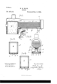
- Figure 1 represents a longitudinal sectional view of a locomotiveboiler provided with my improvements.
- Fig. 2 represents a section on line 2 2 of Fig. 1.
- Fig. 3 represents a section on line 3 3 of Fig. 2.
- Fig. 4 represents a section on line 4 4 of Fig. 2.
- Fig. 5 represents a perspective view of the recessed plate or shell hereinafter referred to, the same letters designating the same part or features, as the case may be, wherever they occur.
- a represents a locomotive- Serial No. 421,519. (No model.)
- boiler having the tubes or flues a and waterleg a surrounding the fire-box b, all being of the usual or any suitable general form and construction.
- I form an orifice 0 in the shell of the boiler at the lower portion thereof, and in the outer wall of the water-leg I form one or more orifices 0, there being, preferably, a horizontal row of the lastmentioned orifices located near the bottom of the water-leg, as shown in Fig. 2.
- a passage 13 which is adapted to conduct water from the forward lower portion of the boiler to the orifice 0.
- Said passage is preferably formed by riveting a strip of metal to the lower portion of the shell of the boiler, said strip having a concavo-convex form in cross-section and provided with flanges p p to receive the attaching-rivets.
- the forward end of the passage formed by said strip and the shell of the boiler is open to receive water, while its rear end is closed behind the orifice 0, as .shown in Fig. 1. I do not limit myself to this manner of making the passage 19, but consider that any construction that will provide a passage within the boiler from the forward portion of the latter to the orifice 0 will be no departure from the spirit of my invention.
- This internal passage economizes space, taking up no room outside of the boiler, so that there is no interference with the parts of the engine be low the boiler. Moreover, the location of the passage within the boiler equalizes the pressure, so that the wall of the passage does not require to be so heavy and strong as if it were on the outside.
- q represents a flanged shell or recessed plate, which is preferably formed, as best shown in Figs. 2 and 5.
- Said shell is adapted to be bolted to the outer wall of the water-leg and to the lower portion of the boiler-shell, and when so bolted it forms a passage connecting the orifice 0 in the shell with the orifices 0" in the water-leg, so that water flows from the passage 19 through said orifices to the water-leg.
- the shell q as here shown, is composed of a horizontal upper portion 2, having a marginal flange 2, formed to fit the bottom portion of the boiler-shell, the verticalportion 3, extending downwardly from the portion 2,
- the upper portion 2 receives water from the orifice 0, while the portion 3 conducts said water downwardly along the outer wall of the water-leg, and the portions 4; 4: deliver it to the orifices o.
- the shell q is the only part of my improvement that is located outside of the boiler, and that said shell is adapted by its form and arrangement to be applied without interference with the mechanism or parts of the locomotive contiguous to thewator-leg and bottom of boiler-shell.
- a mud-drum on may be connected to the lower portion of the boiler at or near the forward end of the passage 1), said drum receiving the greater part of the sediment and foreign matter that is carried by the water and preventing such matter from entering the passage 1).
- a boiler having the usual water-leg or jacket surrounding the fire-box, said boiler having an orifice in the lower portion of its shell, while the water-leg has one or more orifices in the lower portion of its outer wall, combined with a passage within the boiler, adapted to conduct water from the forward portion of the boiler to the orifice in the boiler-shell, and an external connection between the orifices in the boiler-shell and water-leg, said connection having a water-passage of substantially-uniforn1 capacity and located contiguous to the back of the waterleg, as set forth.
- a boiler having the usual water-leg or jacket surrounding the fire-box, said boiler having an orifice o in the lower portion of its shell, while the outer wall of the water-leg has a series of orifices 0' in its lower portion, combined with a passage within the boiler extending along the lower portion of the boiler and adapted to conduct water from the forward lower portion of the boiler to the orifice 0, and an elbow-shaped flanged shell or recessed plate formed to be seated on the bottom of the boiler and on the outer wall of the water-jacket and boiler and forming a conduit connecting theorificeoin the boiler with the orifices in the outer wall of the waterjacket, as set forth.
Description
(No Model.)
W. B.-MAGK.
BOILER.
'Peitented Dec. 6, 1-892;
WITNESSES MEJV " NITED STATES PATENT OFFICE.
WILLIAM B. MACK, OF BOSTON, MASSACHUSETTS.
BOILER.
SPECIFICATION forming part of Letters Patent No. 487,535, dated December 6, 1892.
Application filed February 15, 1 89 2.
To all whom it may concern.-
Be it known that 1, WILLIAM B. MACK, of Boston, in the-county of Suifolk and State of Massachusetts, have invented certain new and useful Improvements in Boilers, of which the following is a specification.
This invention relates to locomotive-boilers in which the forward portion of the boiler is connected by a conduit with the lower portion of the water leg or jacket surrounding the fire-box, the object being to cause an equable circulation of all the water in the boiler audits passage over the hottest parts of the boiler-surfaces. It is awell-known fact that the water leg or jacket surrounding the fire-box develops the greatest amount of heat abstracted from thefuel. Hence any construction whereby the water from the coolest portion of the boilerviz., the lower portion of the forward endis caused to pass quickly and in large volume to the hottest part-viz., the Water-legmust result in a much more efficient action and in the more thorough utilization of the heat. Heretofore attempts have been made to connect the forward lower part of the boiler with the water-leg by means of a pipe or pipes outside of the boiler, said pipe being connected at one end to the boiler and at the other end to the water-leg. This construction is objectionable, because there is not room under the boiler for said pipe and for other reasons.
My invention has for its object to obviate the objections incidental to the connection of the forward lower part of the boiler with the water-leg by an external pipe; and to this end it consists in the improved construction which I will now proceed to describe and claim.
In the accompanying drawings, forming a part of this specification, Figure 1 represents a longitudinal sectional view of a locomotiveboiler provided with my improvements. Fig. 2 represents a section on line 2 2 of Fig. 1. Fig. 3 represents a section on line 3 3 of Fig. 2. Fig. 4 represents a section on line 4 4 of Fig. 2. Fig. 5 represents a perspective view of the recessed plate or shell hereinafter referred to, the same letters designating the same part or features, as the case may be, wherever they occur.
In the drawings, a represents a locomotive- Serial No. 421,519. (No model.)
boiler having the tubes or flues a and waterleg a surrounding the fire-box b, all being of the usual or any suitable general form and construction.
In carrying out my invention I form an orifice 0 in the shell of the boiler at the lower portion thereof, and in the outer wall of the water-leg I form one or more orifices 0, there being, preferably, a horizontal row of the lastmentioned orifices located near the bottom of the water-leg, as shown in Fig. 2.
Within the boilersI form a passage 13, which is adapted to conduct water from the forward lower portion of the boiler to the orifice 0. Said passage is preferably formed by riveting a strip of metal to the lower portion of the shell of the boiler, said strip having a concavo-convex form in cross-section and provided with flanges p p to receive the attaching-rivets. The forward end of the passage formed by said strip and the shell of the boiler is open to receive water, while its rear end is closed behind the orifice 0, as .shown in Fig. 1. I do not limit myself to this manner of making the passage 19, but consider that any construction that will provide a passage within the boiler from the forward portion of the latter to the orifice 0 will be no departure from the spirit of my invention. This internal passage economizes space, taking up no room outside of the boiler, so that there is no interference with the parts of the engine be low the boiler. Moreover, the location of the passage within the boiler equalizes the pressure, so that the wall of the passage does not require to be so heavy and strong as if it were on the outside.
q represents a flanged shell or recessed plate, which is preferably formed, as best shown in Figs. 2 and 5. Said shell is adapted to be bolted to the outer wall of the water-leg and to the lower portion of the boiler-shell, and when so bolted it forms a passage connecting the orifice 0 in the shell with the orifices 0" in the water-leg, so that water flows from the passage 19 through said orifices to the water-leg. The shell q, as here shown, is composed of a horizontal upper portion 2, having a marginal flange 2, formed to fit the bottom portion of the boiler-shell, the verticalportion 3, extending downwardly from the portion 2,
and the horizontal portions 4 4, extending from the lower end of the portion 3, said portions 3 and at being provided, respectively, with flanges 3 4, formed to bear on the outer wall of the water-leg. The upper portion 2 receives water from the orifice 0, while the portion 3 conducts said water downwardly along the outer wall of the water-leg, and the portions 4; 4: deliver it to the orifices o.
It will be seen that the shell q is the only part of my improvement that is located outside of the boiler, and that said shell is adapted by its form and arrangement to be applied without interference with the mechanism or parts of the locomotive contiguous to thewator-leg and bottom of boiler-shell. By thus bringing water from the coolest part of the boiler to the Water-leg and distributing it at the lowest part of the firebox a rapid circulation of water over the surfaces of the firebox is maintained, thus preventing the intense heat at this part from driving the water out of the water-leg. Without this provision for the circulation of water, and in all locomotive-boilers as at present constructed, there is a constant tendencyof the heat from the fire to drive the water upward out of the water-leg. Hence if the water-space is limited there is constant danger of burning out the sheets of the water-leg. It is very desirable on account of efficiency to make the waterspace narrow or limited, and my improvement makes this feasible without danger of injury.
I do not limit myself to the form and construction of the shell q here shown and described, and may use any other suitable external connection between the internal passage p and the lower portion of the water-leg.
A mud-drum on may be connected to the lower portion of the boiler at or near the forward end of the passage 1), said drum receiving the greater part of the sediment and foreign matter that is carried by the water and preventing such matter from entering the passage 1).
I claim 1. A boiler having the usual water-leg or jacket surrounding the fire-box, said boiler having an orifice in the lower portion of its shell, while the water-leg has one or more orifices in the lower portion of its outer wall, combined with a passage within the boiler, adapted to conduct water from the forward portion of the boiler to the orifice in the boiler-shell, and an external connection between the orifices in the boiler-shell and water-leg, said connection having a water-passage of substantially-uniforn1 capacity and located contiguous to the back of the waterleg, as set forth.
2. A boiler having the usual water-leg or jacket surrounding the fire-box, said boiler having an orifice o in the lower portion of its shell, while the outer wall of the water-leg has a series of orifices 0' in its lower portion, combined with a passage within the boiler extending along the lower portion of the boiler and adapted to conduct water from the forward lower portion of the boiler to the orifice 0, and an elbow-shaped flanged shell or recessed plate formed to be seated on the bottom of the boiler and on the outer wall of the water-jacket and boiler and forming a conduit connecting theorificeoin the boiler with the orifices in the outer wall of the waterjacket, as set forth.
In testimony whereof I have signed my name to this specification, in the presence of two subscribing witnesses, this 12th day of February, A. l). 1892.
XVILLIAM l3. MACK.
Witnesses:
O. F. BROWN, A. D. HARRISON.
Publications (1)
| Publication Number | Publication Date |
|---|---|
| US487535A true US487535A (en) | 1892-12-06 |
Family
ID=2556384
Family Applications (1)
| Application Number | Title | Priority Date | Filing Date |
|---|---|---|---|
| US487535D Expired - Lifetime US487535A (en) | Boiler |
Country Status (1)
| Country | Link |
|---|---|
| US (1) | US487535A (en) |
-
0
- US US487535D patent/US487535A/en not_active Expired - Lifetime
Similar Documents
| Publication | Publication Date | Title |
|---|---|---|
| US487535A (en) | Boiler | |
| US357019A (en) | Steam-generator | |
| US243386A (en) | Steam-boiler | |
| US743825A (en) | Fire-tube boiler. | |
| US412438A (en) | Richard watkins-and john dickson | |
| US203986A (en) | Improvement in steam-boilers | |
| US681280A (en) | Steam-boiler. | |
| US262976A (en) | Steam-boiler | |
| US464065A (en) | Steam-boiler | |
| US407229A (en) | William morrison | |
| US415894A (en) | Peters | |
| US180127A (en) | Improvement in steam-generators | |
| US253385A (en) | Water-jacket smoke-box | |
| US280606A (en) | Ohaeles gorton | |
| US326466A (en) | Steam-generator | |
| US238008A (en) | sutherland | |
| US821705A (en) | Sectional boiler. | |
| US261783A (en) | Locomotive-boiler | |
| US184866A (en) | Improvement in fire-boxes for steam-boilers | |
| US463804A (en) | mcqueen | |
| US718525A (en) | Combination scotch and water-tube marine boiler. | |
| US359193A (en) | Steam-generator | |
| US784495A (en) | Fire-box. | |
| US168502A (en) | Improvement in steam-boiler furnaces | |
| US167054A (en) | Improvement in flue and tubular steam-boilers |